


Nomenclature
- $a_j$
$a_j$
-
absolute weight of engineering characteristics
-
$R_{ij}$
-
relationship matrix of what vs how
-
$C_i$
-
importance to customer column vector
-
$b_j$
-
relative weight of engineering characteristics
-
$x_{ij}$
-
decision matrix
-
$r_{ij}$
-
normalised matrix
-
$S^+_i$
-
separation from the positive ideal solution
-
$S^-_i$
-
separation from the negative ideal solution
-
$c_i$
-
overall closeness


1.0. Introduction
Joining has been acknowledged as a crucial enabling technology for revolutionary and sustainable production among the several manufacturing technologies. Manufacturing a product without connection of any form is typically not possible due to functional requirements and technological constraints [Reference Martinsen, Hu and Carlson1]. The manufacturing of aircraft uses different materials and hence utilises different similar and dissimilar material joining technology. Therefore, it is crucial to understand the nature of various joining technologies and come up with the most feasible and efficient joints. The goal of achieving lightweight and efficient structures with improved properties can be accomplished by hybrid (multi-material) structures which are the combination of several materials. The required performance is achieved by utilising this combination of materials and their distinctive properties. The hybrid structures have been utilised in several sectors such as the automotive industry, aerospace industry, marine application and construction industry [Reference Khan, Khan, Awais and Khushbash2]. The components made from dissimilar materials are joined using different joining methods depending upon the required design constraints. The biggest challenge in joining dissimilar materials is that their thermal, electrical, mechanical and chemical properties are different from each other. These disparities among the stated properties of these materials lead to issues for both the structural reliability of the joint and the joining method being utilised. Hence, the joining of components has proved to be a complex task as it covers a wide spectrum of materials, approaches and methods [Reference Maggiore, Banea, Stagnaro and Luciano3]. The use of composites in the production of hybrid structural joints, in which composites are connected with other metals such as steel and aluminum for lightweight purposes, was particularly prevalent. Multiple fastening technologies have been used for the production of hybrid joints to date, each with its own advantages and disadvantages.
Conventional stages of product design consist of the conceptual, preliminary and detail phases. Each phase is defined by varying levels of understanding commensurate with the significance of the choices that must be made at its conclusion. The goal of conceptual design is to establish a product configuration that achieves system-level goals, subject to economic and technical constraints. Typically, semi-empirical analytic methodologies are used to assess the design. These methods usually combine simplified physical models with correction factors derived from already manufactured airplanes and are thus best suited for predicting the future of products with similar design and technology [Reference Sinsay4,Reference Pramanik, Basak, Dong, Sarker, Uddin, Littlefair, Dixit and Chattopadhyaya5]. Numerous findings of extensive studies on CFRP and metal joining may be found in the existing literature. In spite of this, it is difficult to have a comprehensive grasp of this topic owing to the unorganised and vaguely linked scientific findings acquired. Our present research examined several composite joining techniques and utilised the existing integrated process and product design techniques to propose a methodology for identifying the appropriate joining method for joining dissimilar materials.
The schema of the article comprises Section 2 which describes a thorough state-of-the-art review of fastening technologies, selection methodologies and design spaces. Section 2 also describes the main research investigations conducted to choose various joint configurations and the significance of IPPD techniques. Section 3 briefly explains the research methodology. Sections 4–6 utilises the above developed methodology to implement integrated QFD-TOPSIS for dissimilar material joint selection. Section 7 briefly explains the experimental validation of the existing framework. The mechanical behaviour of the joints and failure modes are also discussed in this section. The conclusions from this research are explained in Section 8.
2.0. State-of-the-art
Several methods have been devised to fasten components or parts in various applications. This segment of the paper reviews various permanent fastening methods that range from mechanical, chemical and thermal techniques followed by hybrid methods that utilise the combination of one or two of the techniques. This section also discusses the design and selection methodologies available in the literature for multi-criteria decision making. There are a variety of real-world applications involving the joining of dissimilar materials. For the bolted and riveted joints connecting members need a hole created by machining processes such as drilling. However, this will result in process deficiencies such as delamination, degradation in mechanical properties of composites, and stress concentration around the hole, hence reducing the joint’s strength [Reference Matsuzaki, Shibata and Todoroki6]. Bolt connection is quick to install and disassemble, and has a satisfactory airworthiness certification; hence, bolted joints are still employed in aerospace and aviation structures, particularly for load-bearing structures with excess loads. The mechanical connection necessitates a drilling hole, and thus results in poor sealing performance and causes damage to the composite material [Reference Dawei, Qi, Xiaoguang and Shengdun7]. Similarly, adhesive bonding is the technique of adhering two elements together using an appropriate binder (i.e. an adhesive). In the aviation, automotive and construction industries, adhesives are often used to join together pieces formed of various materials. Adhesive bonding between CFRP and aluminum alloys is the most traditional approach, having both pros and cons. As adhesive bonding is an irreversible process, efforts to disassemble the connections may be costly and end in the full destruction of the joint materials. In addition to sealing the seams, adhesive bonding minimises crevices and galvanic corrosion between dissimilar materials. This approach may join almost any pair of different materials, such as metals, polymers and ceramics [Reference Maggiore, Banea, Stagnaro and Luciano3]. In comparison to other assembly methods and innovations, adhesive bonding enables light weight structures, especially in the aviation industry. In addition, stress concentration is reduced without the need for bolt holes, preventing structural weakness. Porosity is a manufacturing-induced defect preset in the adhesive joints and can significantly degrade the strength of the joint. The effect of porosity on failure mode, and damage mode is considered vital for a design of joint [Reference Khan, Khan, Khan, Salamat, Javaid and Khan8]. The main governing factor of the porosity includes insufficient surface preparation which leads to the formation of voids at the interface of adhesive and adherent. Improper mixing and inaccurate curing of the adhesive layer are considered the factor that governs void formation within the adhesive layer. During the design and development of the adhesive joint, the effect of porosity must be kept in mind as it causes stiffness degradation of the joint. Welding is a manufacturing method in which two or more pieces are joined using heat, pressure, or a combination of the two to produce a joint while the part cools. Welding is often performed on metals and thermoplastics. However, this approach is only applicable to a limited number of thermoplastic composites. Moreover, certain materials need the use of certain processes [Reference Möller, Thomy, Vollertsen, Schiebel, Hoffmeister and Herrmann9]. There are several forms of welding used for various utilisation under varied circumstances. They are forge welding, arc welding, oxy-fuel welding, shielded metal arc welding, gas metal arc welding, submerged arc welding, flux-cored arc welding, electro-slag welding, laser beam welding, electron beam welding, magnetic pulse welding and friction stir welding. Microwaves, induction heating, and friction heating have reportedly been used to achieve localised melting of thermoplastic matrices [Reference Wise10]. The presence of porosity in weld joints significantly deteriorates joint performance. The joint failure takes place at the porous zone, but not at metal/CFRP bonding interfaces. Porosity is produced inside CFRP for all joining parameters with uneven shapes and sizes ranging from ten to hundreds of microns [Reference Lambiase, Scipioni, Lee, Ko and Liu11].
Hybrid joining procedures combine two or more joining methods to produce distinctive properties and the results are often beneficial. These hybrid processes are often more recent in their inception and were designed to address limitations of the underlying processes for immensely challenging applications (e.g., advanced aerospace structures). Combining an adhesive with another joining process improves static and dynamic fatigue resistance, stress distribution, peel and impact resistance, structural weight, load sharing, sealing characteristics, continuous joints and safety [Reference Grant, Adams and da Silva12,Reference Khan, Iqbal, Mehmood and Afshan13]. Therefore, multi-material joining between metals and composites is being developed rapidly in order to achieve the maximum advantages provided by both kinds of materials. Special joining procedures are required to join such types of material components with polymer-metal multi-material systems. Hybrid techniques combining mechanical fastening, adhesive bonding and welding are the most common of these.
Adhesives, mechanical fasteners, welding and hybridisation of these techniques are all viable options, but there are many factors to consider before selecting on one joining technique. It must be noted that the various joining procedures are not typically in competition with one another and should alternatively be seen as complementary. For each application, the finest technological and economic trade-off should be decided for the appropriate joining method [Reference Kweon, Jung, Kim, Choi and Kim14]. The selection of the appropriate material is a challenging process that requires the management of a large quantity of data regarding the material characteristics and user requirements and there are sometimes many choices for a given application. After using one of the other initial screening approaches to restrict the field of outstanding candidates, ranking methods may be used to further reduce the field of potential elements to a few optimal choices. In the relevant studies, MCDM techniques [Reference Emovon and Oghenenyerovwho15–Reference Akram, Khan, Shams and Mavris19] and optimisation methodologies [Reference Rajput and Datta20–Reference Acharya, Saini, Sundaram and Kumar24] have been employed for the selection process. Multiple objective decision making (MODM) and multiple attribute decision making (MADM) are the two primary types of MCDM [Reference Toloie-Eshlaghy and Homayonfar25]. Each of the aforementioned types had its further classification based on limitations and utilisation and are depicted in Fig. 1. For instance, MADM has been further classified into subdomains named a few ELECTRE, AHP, TOPSIS, etc. ELECTRE is a non-compensatory decision making technique that signifies that a poor performance on one criterion cannot be compensated for by a good performance on another criterion. This is important in many engineering problems where the decision makers cannot simply trade off one criterion against another. In a similar context, the analytic hierarchy process (AHP) is a structured technique for organising and analysing complex decisions, based on mathematics and psychology. Similarly, selection using optimisation techniques can also be further classified into three parts: in-house mathematical coding; simulation-based optimisation; and generic algorithm such as MOGA. Every selection approach has its own features and may be used with one another or with fuzzy algorithms as per requirement.
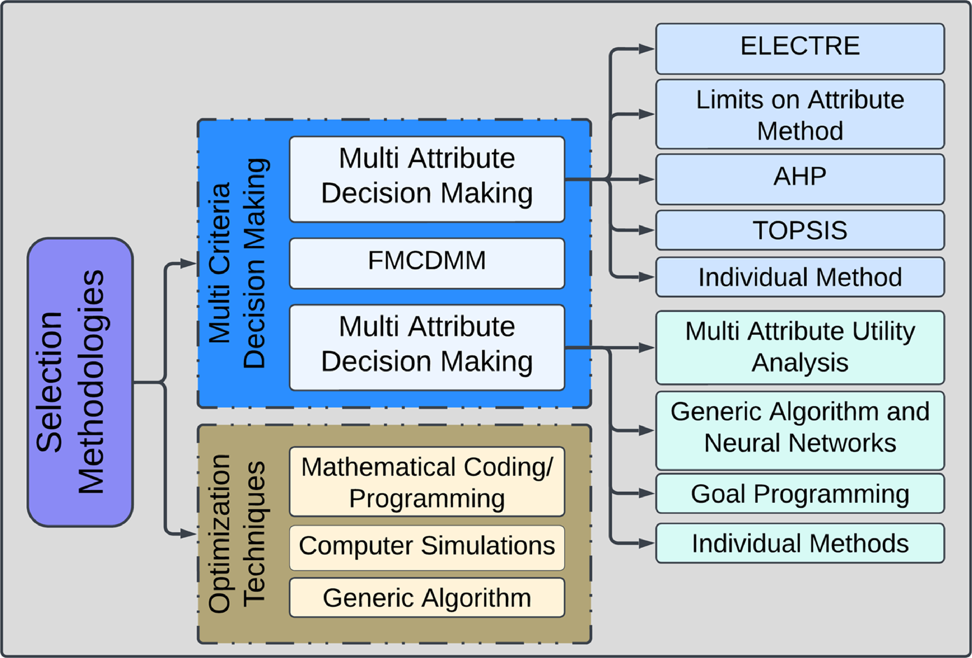
Figure 1. Classification of selection methodologies for decision making.
In modern research, the performance of materials is assessed based on numerous factors in contrast to a single criterion. MADM is a technique for selecting the ideal choice for an engineering product and process design among two or more alternative materials based on multiple user-required characteristics. The characteristics of decision making may be quantitative or qualitative. Several of these character traits can be expressed as numbers, such as mass or thermal expansion; others are Boolean, such as the ability to be reprocessed or abrasion resistance or corrosion resistance can only be expressed as a ranking (poor, adequate and good) [Reference Jahan, Ismail, Sapuan and Mustapha26]. TOPSIS focuses on the concept that the best or positive ideal solution has the finest properties for all criteria and the negative ideal solution has the worst values for all criteria. In other words, the best solution will be the one that has the shortest distance to the positive ideal solution and the longest to the negative ideal solution. TOPSIS is now being used in various fields where decision making is very crucial such as medicine, energy, design and manufacturing of systems, chemical engineering, environment and safety field and water resources studies [Reference Behzadian, Otaghsara, Yazdani and Ignatius27]. Jee and Kang [Reference Jee and Kang28] presented a hybrid of entropy and TOPSIS as a computer-aided engineering (CAE) approach to assist in the selection of materials by designers and engineers. In their research, the best material selection technique for a flywheel has been devised. Milani et al. [Reference Milani, Shanian, Madoliat and Nemes29] used entropy and TOPSIS in gear material selection and examined the influence of normalising parameters on material ranking. Shanian and Savadogo [Reference Shanian and Savadogo30] explored the use of TOPSIS as a MADM technique for addressing the challenge of choice of materials for metallic bipolar plates in polymer electrolyte fuel cells. Due to the fact that the entropy approach for determining the relative significance of characteristics does not account for user preferences, a revised entropy method was implemented to calculate the relative value of each criterion in their research. In addition, they compared the standard TOPSIS approach to a modified version and demonstrated the performance of the new method. Huang et al. [Reference Huang, Liu, Liu and Pan31] used the potential solutions search algorithm (PSSA) to pre-select the materials in order to achieve feasible solutions and then employed the TOPSIS approach to obtain the best solution. Rao and Davim [Reference Rao and Davim32] presented a framework model for the selection of materials based on an integrated multiple-attribute decision making process. The approach used a combination of TOPSIS and AHP. There are a number of reasons that make TOPSIS a viable option for selection and decision making. It is straightforward and fast as compared to other existing methodologies. Moreover, it is beneficial for qualitative and quantitative data. Using a methodical method is reasonably straightforward and quick. The results may be expressed as a numerical value that indicates the user’s preference among the choices and helps in comparing them. This is primarily beneficial when addressing a large number of options and criteria. This approach is also well suited for integrating with computer databases associated with the choice of components [Reference Jahan, Ismail, Sapuan and Mustapha26]. In the past, a number of MCDM techniques have been used in combination with QFD for the selection process in a wide variety of sectors. While there is a gradual increase in interest in QFD applications in dissimilar material joining, the literature has only a small number of studies on QFD applications related to material joining. In a study conducted by Malekly et al. [Reference Malekly, Mousavi and Hashemi33] fuzzy integrated technique for assessing conceptual bridge design was studied. QFD was used to transform the project requirements into design specifications. In the second phase, TOPSIS was used to choose the optimal structure alternative based on the weighted criteria determined in the previous phase. Throughout the procedures, linguistic elements were used to determine the rating values and characteristics for each possibility and option in a fuzzy environment. In conclusion, a study demonstrating the application of the integrated approach for bridge structure design was presented. Sohn and Choi [Reference Sohn and Choi34] investigated the hierarchies of QFD to systematically integrate customer requirements with design characteristics in each supply chain of the PC manufacturing industry’s product development process. Wu et al. [Reference Wu, Liu and Nie35] proposed a breakthrough integrated QFD model and TOPSIS technique for manufacturing process performance evaluation and quality of design. For this purpose, the QFD model was used to determine the absolute weight criterion and HOQ was developed to cope with different sorts of vague inputs. The TOPSIS approach was used to assess the decision making process of product design quality. The outcome is produced by aggregating the results of the best alternative. Several methods have been devised to fasten components or parts in various applications. However, a rudimentary amount of research is available discussing the integrated QFD-TOPSIS approach for the selection of dissimilar material joining. In this paper, a comprehensive technique has been proposed which incorporates quality function deployment (QFD) and TOPSIS in order to find the best fastening techniques for dissimilar materials in aerospace applications. Three material configurations are considered are composite aluminum, composite steel and aluminum steel. For each of these configurations, five basic fastening technique rivet, weld, adhesive, adhesive + rivet and adhesive + weld has been selected to be compared. Weights from the QFD are transferred to the decision matrix to be used in TOPSIS.
3.0. Methodology
The purpose of this research is to examine the most suitable fastening technology for dissimilar materials being used in aerospace applications. Integrated process and product design techniques are used as the advanced design methodology. IPPD method helps the designers to achieve certain trade-off studies to come up with the most suitable alternative. Once the problem has been defined, which in our case is a selection of fastening technology, the IPPD methodology is composed of the following important steps. Identify customer needs and translate them into technical requirements using QFD. This involves determining the key characteristics of the joint that are important to the customer and translating them into specific technical requirements. Develop a set of evaluation criteria based on the technical requirements identified in Step 1. These criteria will be used to evaluate the performance of different joint options. Assign weights to each evaluation criterion based on their relative importance using QFD. This will help to ensure that the most important criteria are given the appropriate level of consideration during the decision making process. Evaluate each joint option on each criterion using TOPSIS. This involves normalising the data for each criterion, calculating the weighted sum of the criteria for each option and then ranking the options based on their similarity to the ideal solution and their distance to the worst-case solution. Review the results of the TOPSIS analysis and select the joint option that best meets the technical requirements and customer needs identified in Step 1. This involves considering the rankings of each option, as well as other factors such as cost, availability and manufacturability.
In the following case, the alternatives (joints) are joining methods which include rivets, welding, adhesive, adhesive-rivets hybrid joint and bonded-weld hybrid joint. In total three cases are developed for three different configurations of materials that is CFRP with aluminum, CFRP with steel and aluminum with steel. The engineering characteristics obtained from the QFD will be used as the evaluation criteria and the relative weight of these characteristics will be used as the ranked requirements. Data is collected on all concepts using existing resources, and interviews with experts and professionals [Reference Devnath, Islam, Rashid and Islam36]. Figure 2 sums up the schematic representation of the methodology for selecting the best fastening technology.
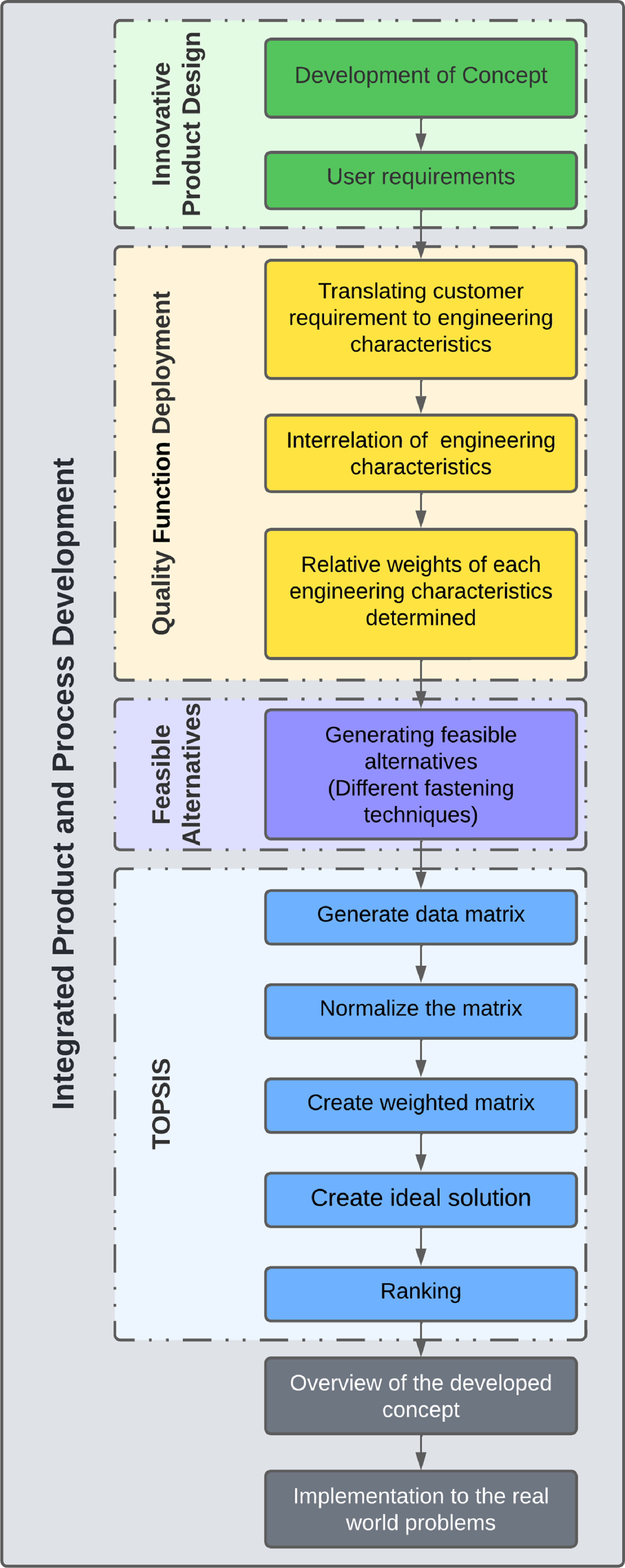
Figure 2. Methodology for the selection of best fastening technology for dissimilar materials.
4.0. Quality function deployment (QFD)
There are five basic components of QFD. The very first component is the design or selection parameters requirements generally termed as the WHATs. For the current study the customer requirement related to the joints are that they should be strong, lightweight, cheap, consumes less time, be durable and material handling should be easy and simple in design. Similarly, the next component is the engineering characteristics or technical descriptors often known as HOWs of the HOQ. The related engineering characteristics are tensile strength, size, deformation, cost per joint, manufacturing ease and time required. The third component is the relationship matrix which relates the WHATs to HOWs. This relationship matrix highlights how strong or weak the relation is between the customer requirements and an engineering characteristic. This relation is scaled using the scores of +9 for the strongest, +3 for moderate, and +1 for the weakest. The fourth component in the QFD is the interrelationship matrix that relates the engineering characteristics with each other. This relation shows how one characteristic is affected by another. The relation is scaled using the scores -9 for very negative, -3 for negative, +3 for positive and +9 for very positive. These scores along with the symbols are also shown in Fig. 3. The fifth component is the relative importance of customer requirements. It tells the percentage importance of a particular requirement specified by the user. The main purpose of constructing QFD is to obtain the relative weight with respect to each engineering characteristic. In order to obtain the relative weight, first we need to compute the absolute weight. The equation to calculate the absolute weight is given:
 \begin{equation}{a_j} = {\Sigma}^n_{i = 1}{R_i}_j{C_i}\end{equation}
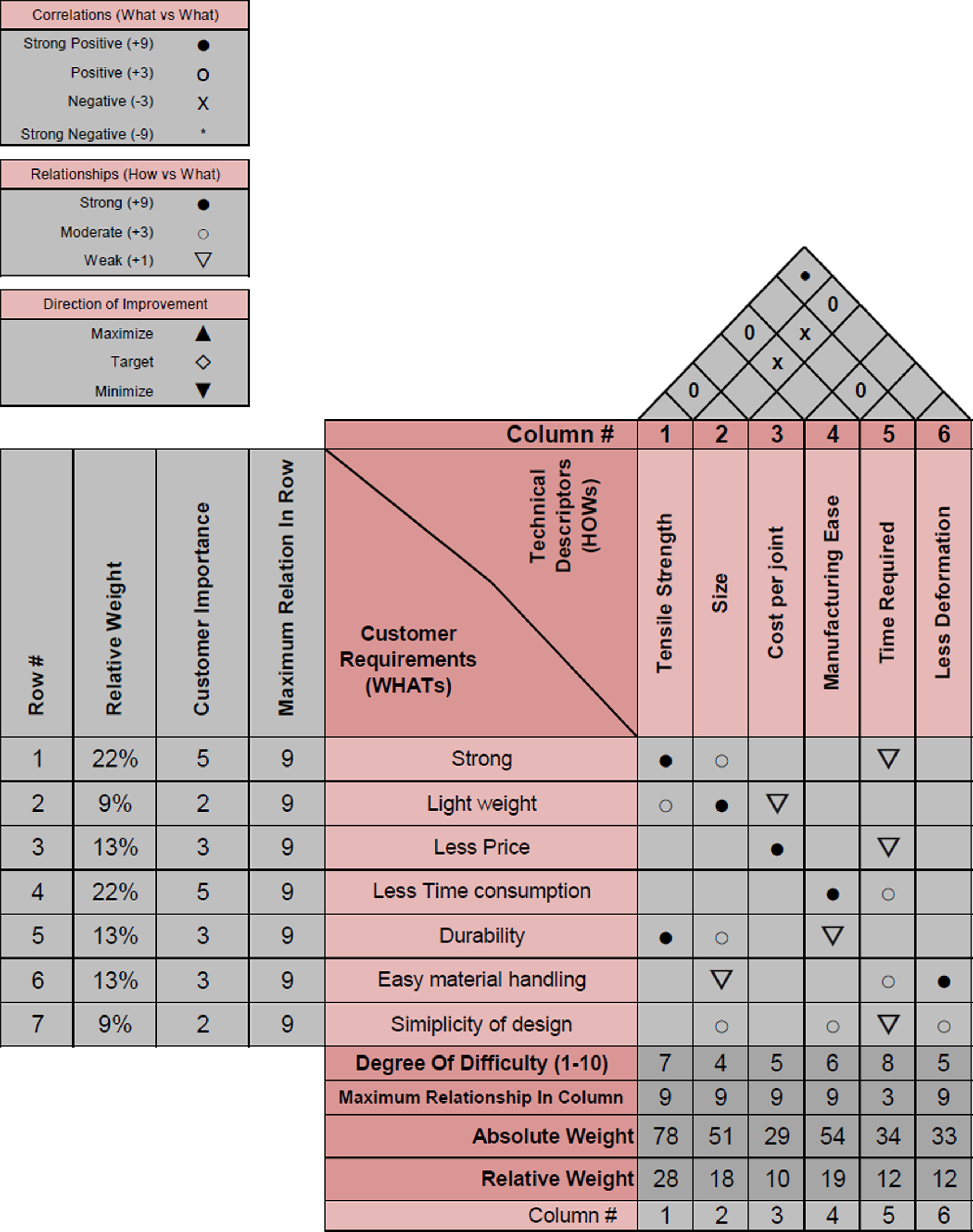
Figure 3. HOQ developed for dissimilar material joining.
The very first engineering characteristic is tensile strength. The absolute weight of this characteristic is calculated as a $a=9\times5+3\times2+9\times3=78$
. In a similar manner, all absolute weights are computed. From these weights, the relative weight of each characteristic is computed using the following equation:
$a=9\times5+3\times2+9\times3=78$
. In a similar manner, all absolute weights are computed. From these weights, the relative weight of each characteristic is computed using the following equation:
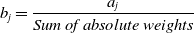 \begin{equation}{b_j} = \frac{{{a_j}}}{{Sum\,of\,absolute\,weights}}\end{equation}
The relative weight of tensile strength becomes b = 78/279 = 0.28 or 28%. In the same manner for all characteristics relative weights are computed as shown in Fig. 3. These weights are then used in TOPSIS for final decision making.
5.0. Decision matrix
The hierarchy list in Fig. 4 shows the alternatives, cases and evaluation criteria to be used in the decision making process.
The decision matrix for the case of two dissimilar materials to be joined together that are CFRP and aluminum is given in Table 1. Design criteria are the factors that are critical to the customer and need to be taken into consideration during the design and development of the product or service. In QFD, design criteria are identified by understanding the customer requirements and translating them into specific technical features or characteristics that will meet those requirements. The technical descriptors reflect the customer requirements and expectations as closely as possible [Reference Malekly, Mousavi and Hashemi37]. For example, The ‘size’ in the technical descriptor is directly related to the weight of the joint, the smaller the size, the less the weight will be. The scale shows 9 for very high, 7 for high, 5 for low, and 3 for very low. A comparative study [Reference Sudirja, Hapid, Kaleg and Budiman38] shows that the weld strength is more than that of the rivet for similar metals, but in the case of dissimilar materials, especially when the composite is involved, conventional arc welding does not yield well. Similarly, the time consumption in rivets is way less than in adhesives as the curing process of adhesive is very time consuming [Reference Baldan39]. Based on such comparative studies and taking aid from the available resources, the following decision matrix is developed. Furthermore, the experts were interviewed based on a semi-structured questionnaire. They were asked to rank each alternative for every criterion.
Table 1. The decision matrix developed after implementing QFD technique
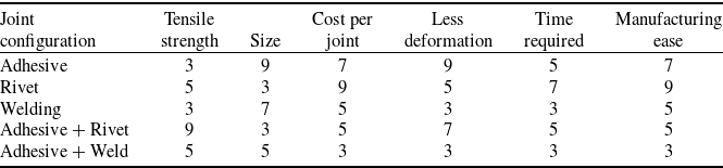
Table 2. Step 1 from TOPSIS normalised matrix
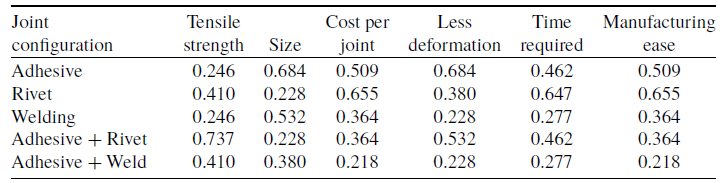
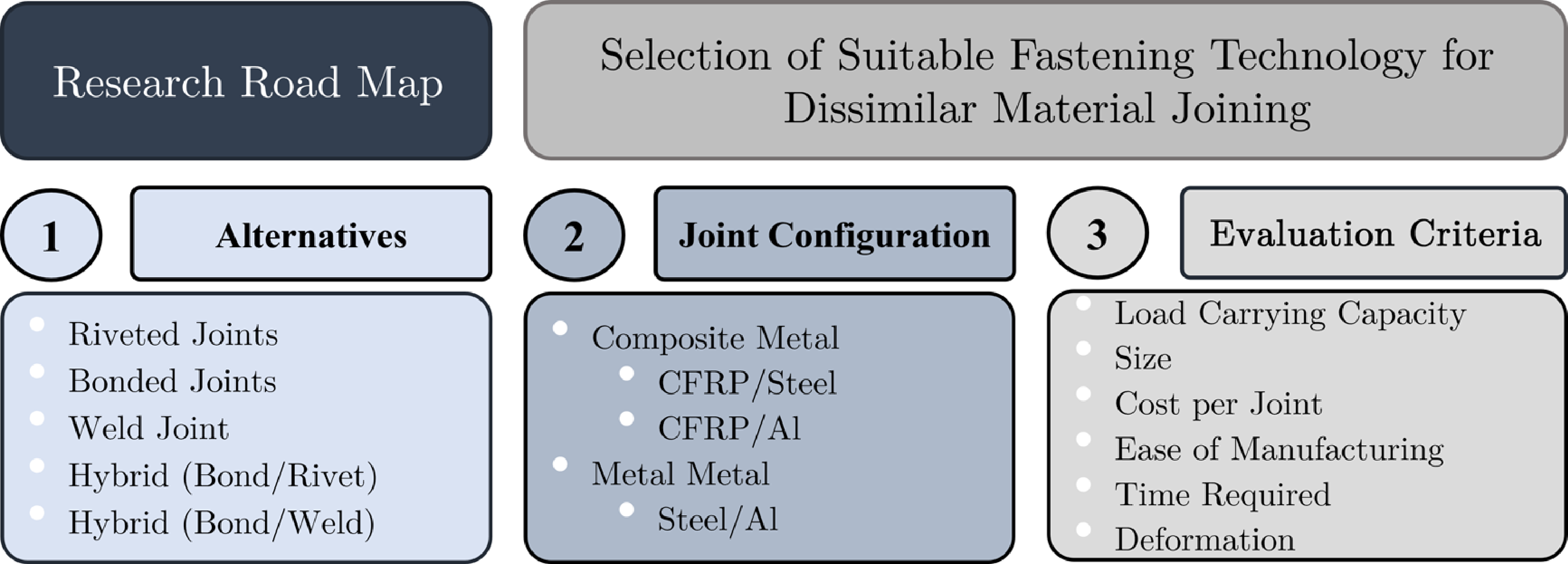
Figure 4. The criteria, alternatives and configuration selected for decision making.
6.0. Topsis
After completing the decision matrix, the next step is to conduct TOPSIS to determine the final option.
-
Step 1: For the given decision matrix, the next step is to normalise the matrix so that all the values are of the same order. The normalisation is done using the following formula:
(3)
\begin{equation}{r_{ij}} = \frac{{{x_{ij}}}}{{\sqrt {\sum\nolimits_{i = 1}^n {{x_{ij}}} } }}\end{equation}

The normalise is given in Table 2:
-
Step 2: The next step is to develop a weighted matrix. The weight for each criterion is obtained from the QFD. The relative weight for each criterion is given as tensile strength = 0.28, size = 0.183, cost per joint = 0.104, less deformation = 0.118, time required = 0.122, manufacturing ease = 0.194. So, the weighted matrix is given as Table 3.
-
Step 3: Identify the positive and negative ideal solutions. This is done by considering the minimum and maximum in the columns of the evaluating criteria. The positive ideal solution will compromise tensile strength = maximum, size = minimum, cost per joint = minimum, less deformation = maximum, the time required = minimum, and manufacturing ease = maximum. Whereas the negative ideal solution will have values totally opposite to that of the positive ideal solution. Table 4 refers to the positive and negative ideal solutions.
-
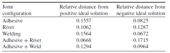
Step 4: The next step is computing the separation from the positive and negative ideal solution. The partition of each alternative from both positive and negative ideal solutions is calculated by the n-dimensional Euclidean distance. The results are depicted in Table 5 and governing equations are given as:
(4)
\begin{equation}S_i^ + = \sqrt {\sum {{(Alternate\,value - Positive\,ideal\,value)}^2}} \end{equation}
(5)
\begin{equation}S_i^ - = \sqrt {\sum {{(Alternate\,value - Negative\,ideal\,value)}^2}} \end{equation}
-
Step 5: Relative closeness to the ideal solution is given by:
(6)
\begin{equation}{c_i} = \frac{{S_i^ - }}{{S_i^ + + S_i^ - }}\end{equation}


Table 3. Weighted matrix evaluated as discussed in Step 2
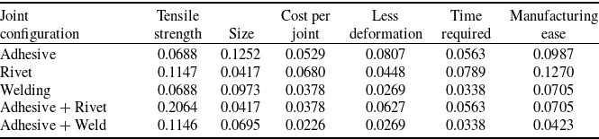
Table 4. Positive and negative ideal solutions identified from Step 3
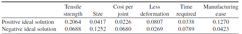
Table 5. Variations from ideal solutions
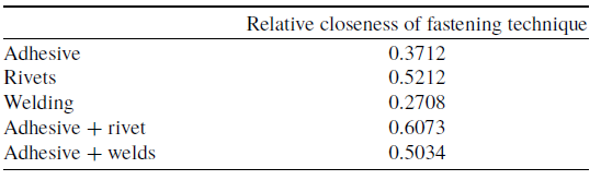
So, the relative closeness is computed for all alternative and are tabulated in Table 6:
Table 6. Relative closeness of fastening techniques
-
Step 6: The final decision is made based on the above results. As it can be seen adhesive + rivet has the shortest distance to the positive ideal solution and is farthest away from the negative ideal solution, so it is concluded that the best possible solution is the adhesive + rivet hybrid joint for the following case. In the following graph, it is quite visible that adhesives and rivet hybrid joint has the best properties as compared to others. Based on the engineering characteristics and the relative weight evaluated for them QFD, this alternative has the shortest distance to the positive ideal solution. It can be said that, in aerospace applications where composite and aluminum will be interacting, the designer can consider a hybrid joint composed of rivets and adhesive.
Similar to the previous calculation, two more decision matrices were generated for composite with steel and steel with aluminum configurations. The graphical representation of the TOPSIS output is also shown in Figs. 5–7. For composite with steel, again adhesive-rivet hybrid joint shows better performance whereas, in the case of aluminum and steel, welding comes out to be the best option in terms of engineering characteristics considered earlier.
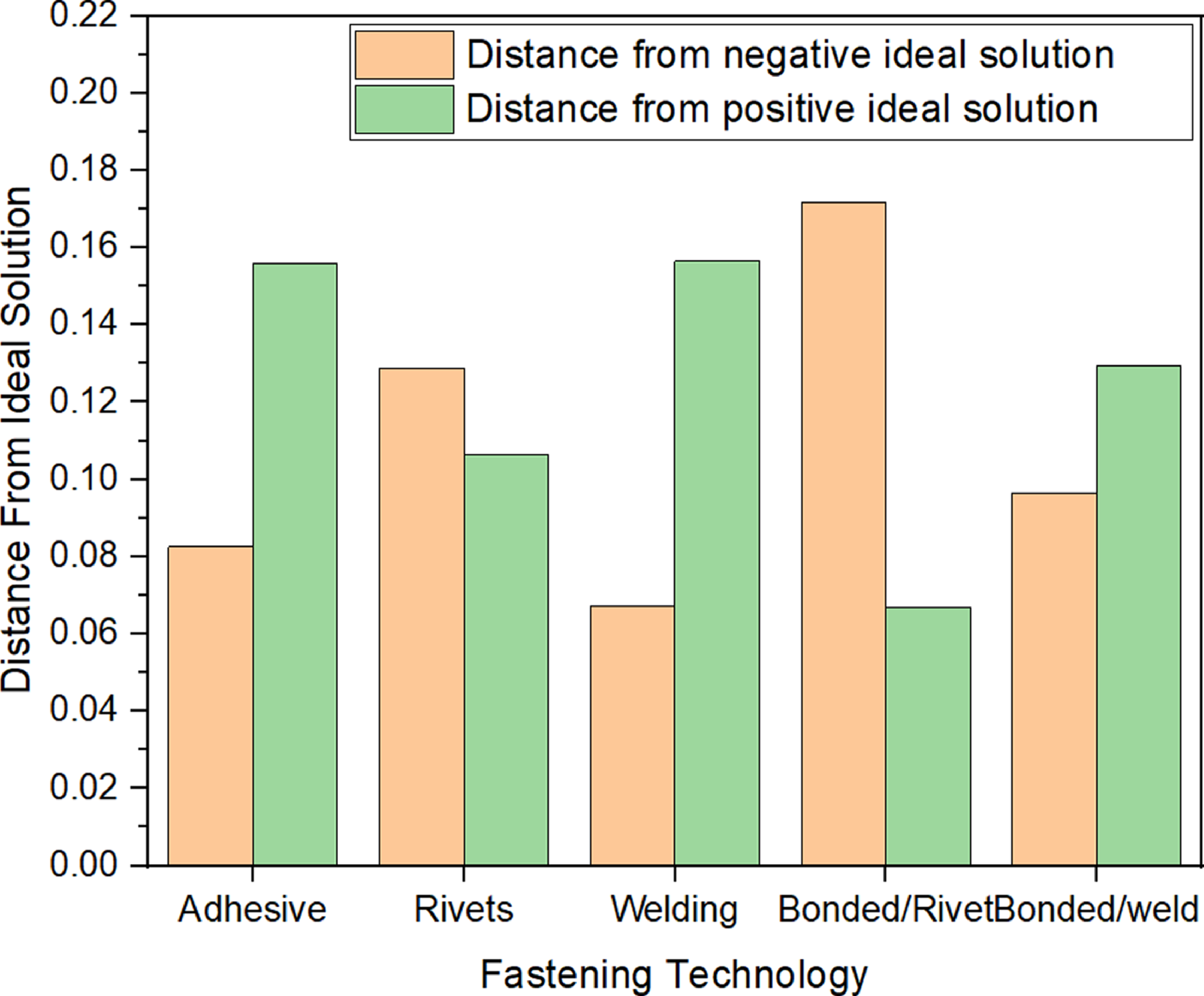
Figure 5. Graphical representation of TOPSIS output for a composite-aluminum interaction.
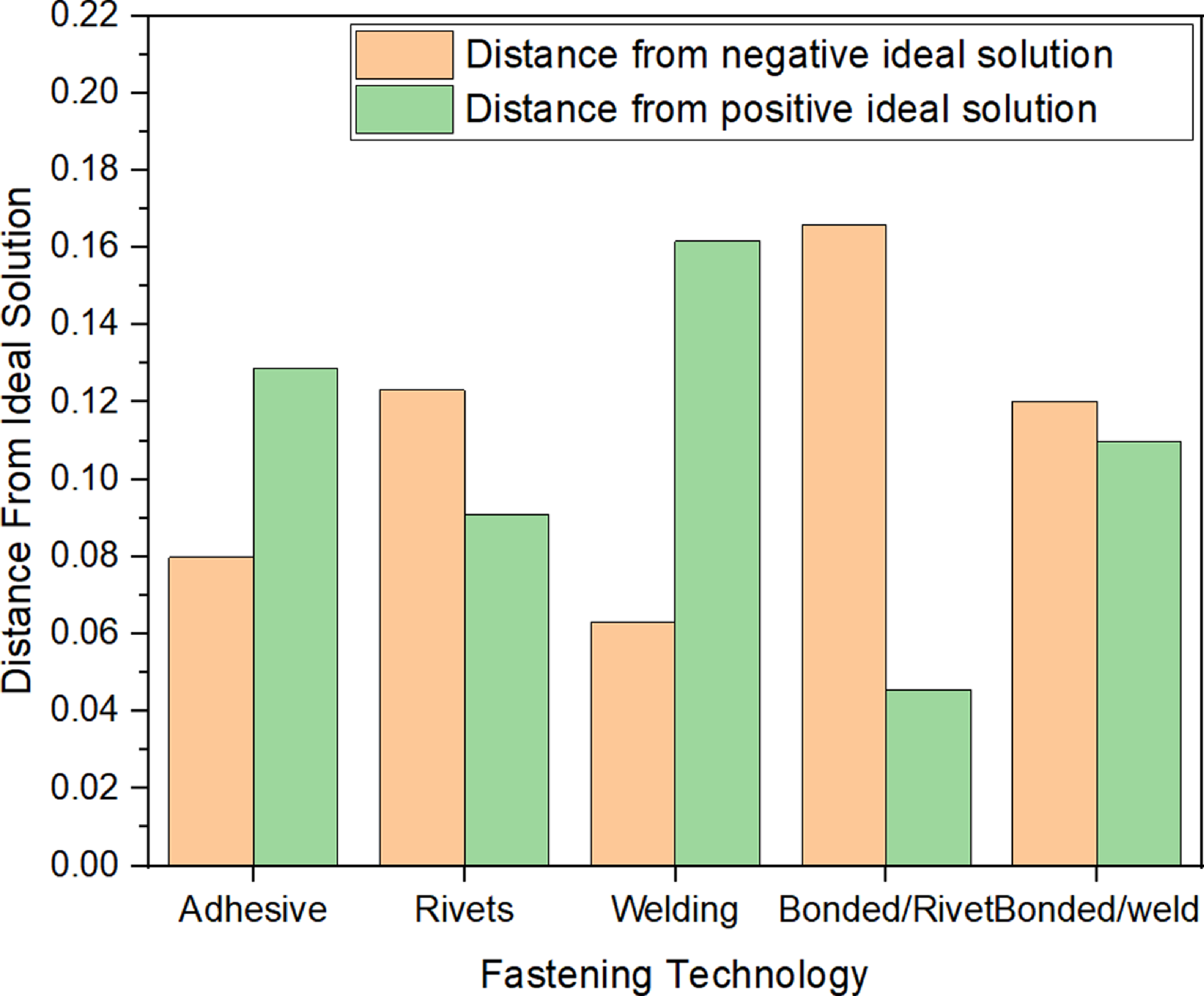
Figure 6. Graphical representation of TOPSIS output for a steel-aluminum interaction.

Figure 7. Graphical representation of TOPSIS output for a composite-steel interaction.
7.0. Validation framework
An experimental analysis has been performed to validate the results acquired from QFD and TOPSIS. The family of composite is so vast that it is nearly impossible to test each and every type of configuration. Hence, the experimental analysis is conducted on riveted, adhesive and hybrid (adhesive-riveted) joints for dissimilar materials including CFRP and aluminum Al-2024.
7.1. Material and specimen preparation
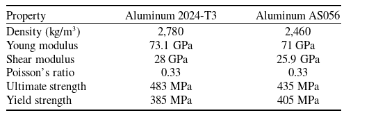
A commercial carbon fiber prepreg with a unidirectional configuration was utilised for the specimen preparation. The lamina was composed of T700S carbon fiber/epoxy resin-3234. The metallic plates were developed from a very common aluminum aerospace alloy Al-2024-T3. For mechanical fasteners, AS056 aerospace-grade aluminum blind rivets were utilised having 4mm of mean diameter. Similarly, HYSOL EA-9430 was used as an adhesive during specimen preparation of adhesive joints. The mechanical properties of CFRP lamina, aluminum plate and aluminum rivet are shown in Table 7 and 8, respectively.
Table 7. Mechanical properties of unidirectional T700S carbon fiber/ 3234 [Reference Khan, Khan, Awais and Khushbash2]
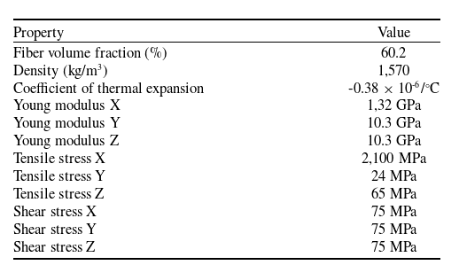
Table 8. Mechanical properties of aluminum and AS056 aluminum rivet [Reference Khan, Zafar, Hameed, Akram, Asim, Javaid and Khan40]
For the fabrication of the composite laminate, the CFRP prepregs sheet was cut into ten laminae having dimensions of 200mm × 200mm using a Zund cutter plotter. The lay-up pattern was chosen to be cross-ply [0 $^{\circ}$
/90
$^{\circ}$
/90 $^{\circ}$
]10 configuration. After the cutting, the plies were stacked up in [0
$^{\circ}$
]10 configuration. After the cutting, the plies were stacked up in [0 $^{\circ}$
/90
$^{\circ}$
/90 $^{\circ}$
]10 cross-ply orientation. Pre-processing of the laminate was performed using vacuum bagging as per ASTM D5867 [41], before curing the laminate in autoclave. The autoclave operated at a maximum temperature of 130
$^{\circ}$
]10 cross-ply orientation. Pre-processing of the laminate was performed using vacuum bagging as per ASTM D5867 [41], before curing the laminate in autoclave. The autoclave operated at a maximum temperature of 130 $^{\circ}$
C for two hours with a ramp of 2
$^{\circ}$
C for two hours with a ramp of 2 $^{\circ}$
C/min. The pressure of 7 bar was applied to ensure the removal of air bubbles and voids in the laminate. A cooling rate of 1
$^{\circ}$
C/min. The pressure of 7 bar was applied to ensure the removal of air bubbles and voids in the laminate. A cooling rate of 1 $^{\circ}$
C/min was applied till the chamber temperature of the autoclave reached room temperature. The laminate and aluminum alloy sheets were then sectioned using a water-cooled diamond cutter. The specimen configurations consisted of single lap joints composed of CFRP/Al riveted SLJ, CFRP/Al adhesive SLJ, and CFRP/Al hybrid SLJ.
$^{\circ}$
C/min was applied till the chamber temperature of the autoclave reached room temperature. The laminate and aluminum alloy sheets were then sectioned using a water-cooled diamond cutter. The specimen configurations consisted of single lap joints composed of CFRP/Al riveted SLJ, CFRP/Al adhesive SLJ, and CFRP/Al hybrid SLJ.
For the adhesive joint, adherend was first prepared which involves washing the coupon, identifying the surface of bonding, degreasing, etching and finally drying of the specimen. Then, the preparation of the adhesive was performed by homogenously mixing the epoxy and hardener in a 100:23 composition. After the preparation of adhesive, it is applied on the adherend (CFRP and Al) to fabricated dissimilar single lap joint. The samples were further cured at 120 $^{\circ}$
C for 2 hours. The hybrid joints were also developed following both the procedure of adhesive joint and riveted joint. The dimensions of the prepared specimens following ASTM D5961 [42] for riveted, hybrid and adhesive joints are illustrated in Fig. 8.
$^{\circ}$
C for 2 hours. The hybrid joints were also developed following both the procedure of adhesive joint and riveted joint. The dimensions of the prepared specimens following ASTM D5961 [42] for riveted, hybrid and adhesive joints are illustrated in Fig. 8.
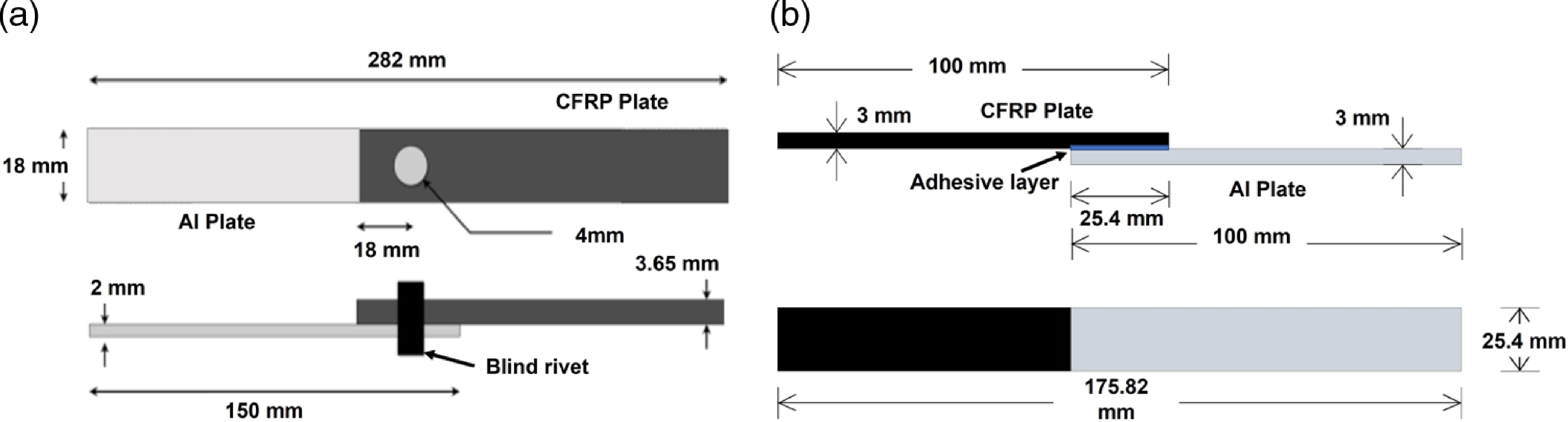
Figure 8. (a) Schematic of the single rivet single lap joint. (b) Schematic of the single lap adhesive joint.
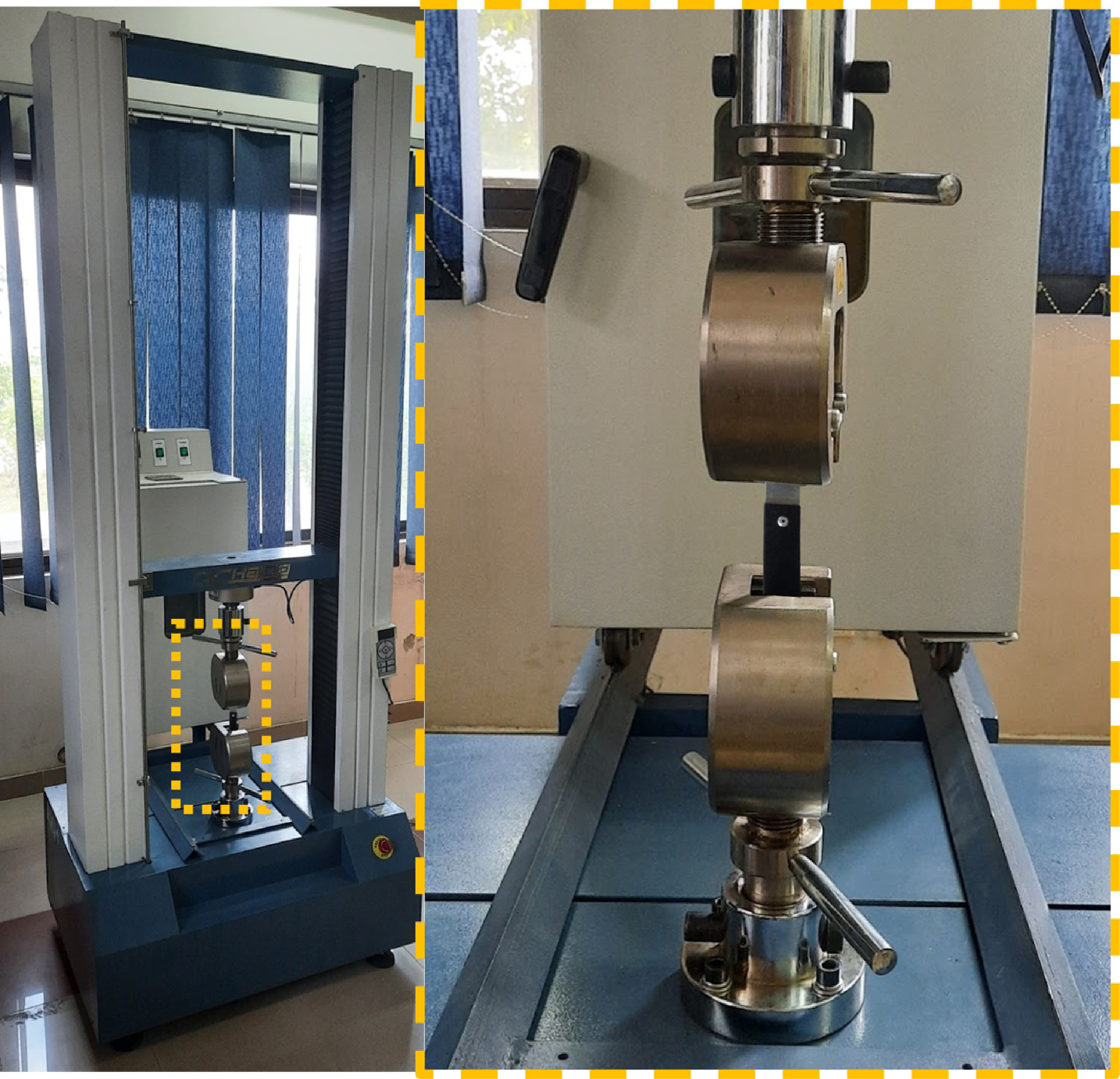
Figure 9. Experimental procedures for the tensile testing of the riveted joints.
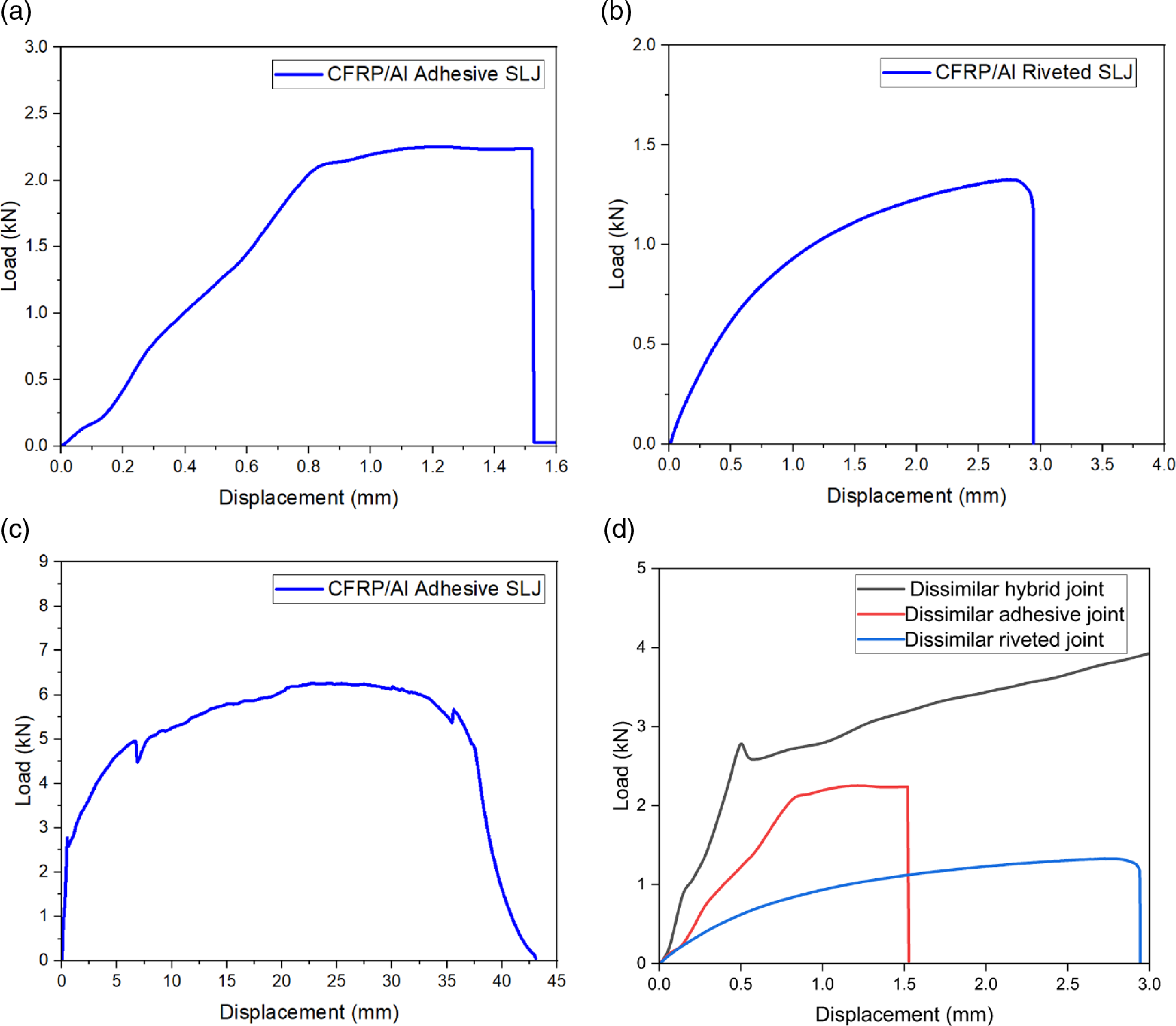
Figure 10. Load displacement curve obtained through tensile testing for CFRP/AI (a) adhesive joints, (b) riveted joint, and (c) hybrid joint, (d) comparison of mechanical behaviour of all three configurations upto 3mm.
7.2. Experimental procedures
To evaluate the mechanical strength of the different joint configurations, uniaxial displacement-controlled quasi-static tensile tests were conducted at room temperature on servo operated universal testing machine (UTM). The displacement rate of 2mm/min was used during the tensile test. The statistical correctness of the obtained data was ensured by testing a total of five samples for each configuration. Further, the failure modes were examined through a stereo microscope by examining the fractured surfaces. Figure 9 depicts the mechanical testing setup for the riveted joint.
7.3. Results and discussion
This section briefly explains the results of the tensile test performed on CFRP/Al hybrid, rivet and adhesive joint. The mechanical response of the said joints is presented in Fig. 10(a)–(d). The purpose of the test is to validate the results of quality function deployment and TOPSIS that were used for the development of design space for dissimilar material joints. The ultimate failure loads for the specimen are given as 7.5kN, 2.25kN and 1.4kN for hybrid, adhesive and riveted joints, respectively. In a similar context, it must also be noted that the failure mechanism also showed distinct behaviour for all three joint configurations. In the rivet joint, the rivet failed in shear failure mode. However, in the adhesive joint, cohesive failure was observed in the joint. The adhesive thin film present between the dissimilar material plates failed in shear mode and it was seen that the adhesive separated in such a way that the adhesive layer partially remained attached to one adhered and partially to the other plate. The hybrid joint showed mixed mode failure, with adhesive taking the load at the start and failing in shear mode. After the partial or complete failure of the adhesive, the mechanical rivet starts to bear the mechanical load and ends up failing in shear mode. Thus in terms of load bearing capacity, the experimental results are in good agreement with the proposed methodology.
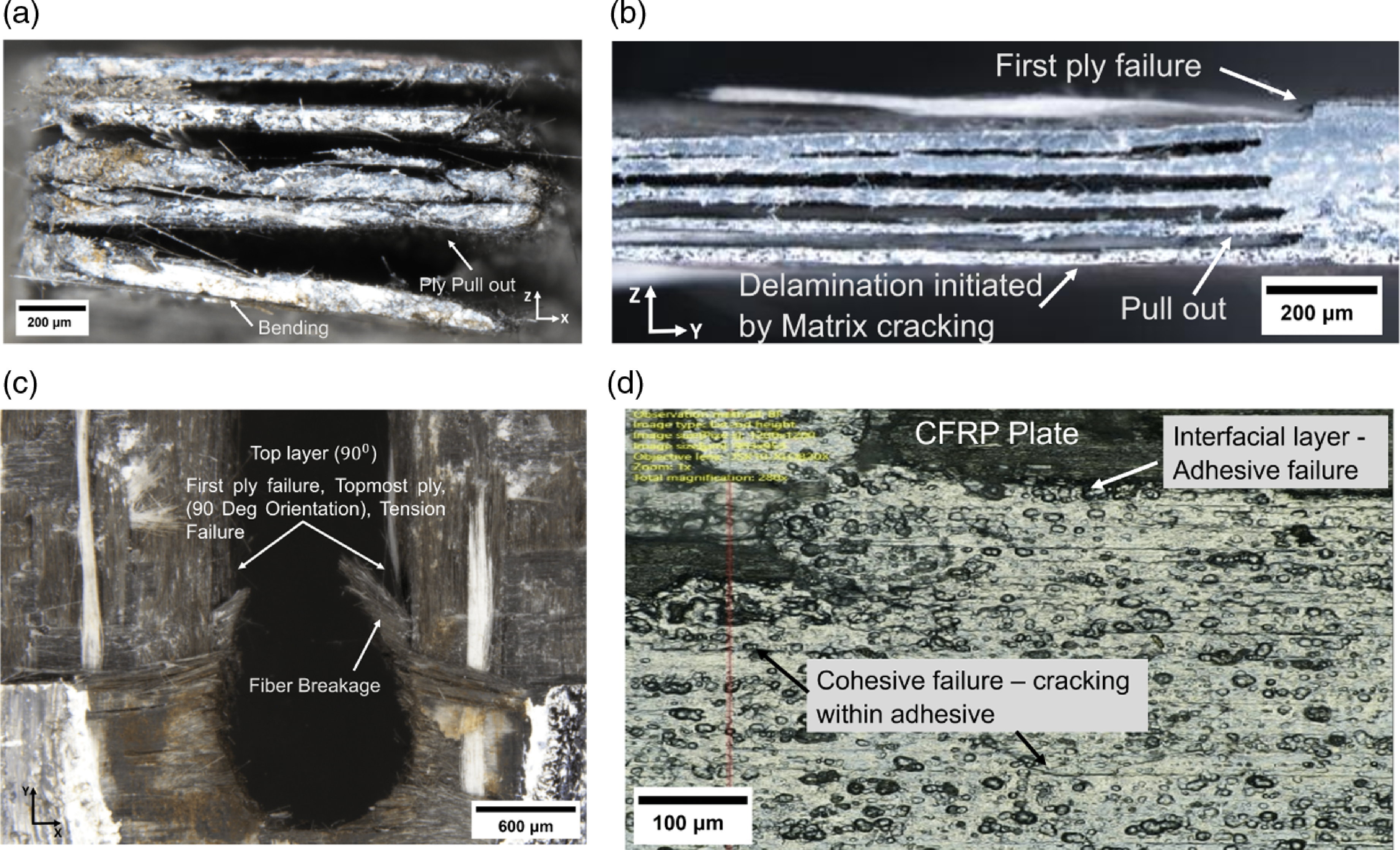
Figure 11. Fractures surface of the failed CFRP laminate (a) depicting bending and ply pull out from front view; (b) critical ply and delamination from side view; (c) first ply failure and fiber breakage from front view; (d) inter-facial adhesive failure and cohesive failure in adhesive joint.
Figure 10(d) depicts the comparison of three configurations of CFRP/Al joint. It can be seen that the riveted joint failed at the minimum load but has higher ductility as compared to the adhesive joint. The adhesive joint failed at 2.25kN tensile load with a minimum deformation of 1.54mm. The hybrid joint exhibits the characteristics of both the riveted and adhesive joint. The hybrid joint can withstand 4kN of tensile force with a maximum deformation of 3mm without any failure.
7.4. Failure modes
After the tensile testing, the fractured surfaces of the joints were examined to evaluate their failure modes and are depicted in Fig. 11(a)–(d). It is pertinent to mention that in all the joints, the CFRP laminate experienced failure. However, no failure was observed for the metallic constituents, i.e., the sheet and the rivet, of the joints. In the riveted joint, the CFRP failed in tension with fiber breakage and matrix cracking as dominant failure modes. There is a non-uniform secondary bending visible in CFRP (Fig. 11(a)). Moreover, it can also be seen from Fig. 11(b) and (c) that each orientation of the plies has a distinct failure mode. The 0 $^{\circ}$
ply failed in bearing and tension, whereas in 90
$^{\circ}$
ply failed in bearing and tension, whereas in 90 $^{\circ}$
plies fiber breakage leading to fiber pull-out is observed. In the same context, adhesive joint, mixed mode failure is observed in adhesive joint comprising cohesive and adhesive failure mode as depicted in Fig. 11(d). Lastly, mixed mode failure occurred in the hybrid joint and CFRP. It failed in tension having fiber breakage, pull-out and matrix cracking coupled with mix mode (adhesive failure and cohesive failure) failure. Similar failure modes as observed in the other two joints were noted and the fractured surfaces were not shown to avoid duplication.
$^{\circ}$
plies fiber breakage leading to fiber pull-out is observed. In the same context, adhesive joint, mixed mode failure is observed in adhesive joint comprising cohesive and adhesive failure mode as depicted in Fig. 11(d). Lastly, mixed mode failure occurred in the hybrid joint and CFRP. It failed in tension having fiber breakage, pull-out and matrix cracking coupled with mix mode (adhesive failure and cohesive failure) failure. Similar failure modes as observed in the other two joints were noted and the fractured surfaces were not shown to avoid duplication.
8.0. Conclusions
In this study, an IPPD method (QFD-TOPSIS) was selected to determine the most appropriate fastening technology for three distinct configurations of dissimilar materials used in aerospace applications. This article examines rivet, weld and adhesive as the fundamental fastening methods. While adhesive-rivet and adhesive-weld joints are chosen as two hybrid joints, QFD was implemented to translate design requirements into engineering characteristics as an initial step. These engineering characteristics became the basis for decision making evaluation criteria. A decision matrix was constructed, and relative weights were assigned to each evaluation criterion based on the results of the QFD. As a result of TOPSIS, it was determined that the adhesive-rivet hybrid joint is the best option for the configurations of composite-aluminum and composite steel, whereas welding was the best option for the aluminum-steel combination that is typically used to achieve super-structural integrity. In addition, the findings of the tensile tests performed on the composite-aluminum samples were consistent with the selection criteria. Following is the strength of the composite/Al joint:
CFRP/Al Hybrid Joint > CFRP/Al Adhesive Joint > CFRP/Al Riveted Joint
This shows that the proposed selection methodology of IPPD methodology can be used for joint selection in the conceptual design stages.


 Open access