NOMENCLATURE
- CD
-
drag coefficient (-)
- D1
-
total capsule diameter (m)
- D2
-
capsule top diameter (m)
- DRYv
-
dry mass based on volume requirement (similar to OEWv) (kg)
- DRYw
-
dry mass based on geometry and performance (similar to OEWw) (kg)
- L/D
-
lift-to-drag ratio (-)
- LS
-
heat shield length (m)
- LC
-
conical length (m)
- L
-
total capsule length (m)
- ${\dot q_{MAX}}$
-
stagnation point heat transfer rate (W/cm2)
- R
-
base radius (m)
- RN
-
vehicle nose radius (m)
- S
-
area (m2)
- Spln
-
vehicle planform/reference area (m2)
- T/W
-
thrust to weight ratio (-)
- UNW
-
areal weight (kg/m2)
- ΔV
-
orbital change in velocity (m/s)
- WR
-
mission segment weight ratio (-)
- W/S
-
wing loading (N/m2)
- α
-
angle-of-attack (deg)
- β
-
ballistic coefficient (kg/m2)
- Δ
-
increment of a parameter
- ϑ
-
wake impingement angle (deg)
- ψ
-
capsule nose radius arc-angle (deg)
- ACES
-
advanced common evolved stage
- AOTV
-
aero-assisted orbital transfer vehicle
- APM
-
ascent propulsion module
- AR&D
-
autonomous rendezvous and docking
- AVDsizing
-
Aerospace Vehicle Design Laboratory sizing software
- AVD Lab
-
Aerospace Vehicle Design Laboratory
- AVDS
-
aerospace vehicle design synthesis
- CH4
-
methane
- CM
-
crew module
- COBRA
-
co-optimisation of blunt-body re-entry analysis
- CONOP(s)
-
concept(s) of operation
- CTV
-
crew transfer vehicle
- DARPA
-
Defense Advanced Research Projects Agency
- DB
-
data-base
- DBS
-
data-base management system
- DCSS
-
delta cryogenic second stage
- DPM
-
de-orbit propulsion module
- DV
-
ΔV = orbital change in velocity
- GEO
-
geosynchronous earth orbit
- GTO
-
geostationary transfer orbit
- GYO
-
graveyard orbit
- I-A-O
-
input – analysis – output
- ILIDS
-
International Low-Impact Docking System
- ISS
-
International Space Station
- JSC
-
Johnson Space Center
- KB
-
knowledge-base
- KSC
-
Kennedy Space Center
- LEO
-
low earth orbit
- LH2
-
liquid hydrogen
- LOX
-
liquid oxygen
- MAE
-
Mechanical and Aerospace Department
- MGS
-
manned geosynchronous satellite servicing
- NASA
-
National Aeronautics and Space Administration
- NSD
-
Nassi-Shneiderman Diagram
- OTV
-
orbital transfer vehicle
- POTV
-
propulsive orbital transfer vehicle
- ROI
-
return on investment
- SBCM
-
space-based crew module
- SM
-
service module
- STS
-
space transportation system
- TPS
-
thermal protection system
- UTA
-
University of Texas at Arlington
Symbols

Greek Symbols
Acronyms
1.0 INTRODUCTION
The 21st century will witness strategic decisions and subsequent development programs across the globe regarding future space architectures, space missions and individual spacecraft that will shape commercial, military and research space policies for decades to come. As such, it must be recognised that future visions for space tend to evolve dynamically while legacy space systems like the ISS and others will have to adapt and eventually retire. Unlike the early days of space exploration during the 1950s and 1960s, the winners of this modern ‘space race’ will not only have to stimulate even larger investments, but they absolutely have to master the balancing of risk versus potential return on investment.
While this paper does not aim to propose a sustainable space infrastructure, nor does it refine an individual technology at high-fidelity level, it documents the effort undertaken to identify the available multi-disciplinary solution space for candidate space technologies and their impact on a prospective next-generation space mission: manned GEO satellite servicing (undertaking jointly initiated by NASA/DARPA). This feasibility study considers a near-term (five- to ten-year) market entry scenarios by assessing operational (orbital) parameters in combination with hardware (design) parameters. The cost-conscious near-term solution space identified is therefore only considering current-generation launch vehicles and readily available technical capability.
Having identified the feasible near-term mission-technology-hardware manned GEO satellite-servicing solution space, the authors subsequent identify and recommend individual candidate implementation scenarios. The underlying solution-space identification capability and the resulting parametric understanding enable the design team to rapidly explore derivative scenarios for anticipated changes stemming from the mission-technology-hardware and customer ROI requirements. Since the parametric solution space identified relates to a multitude of high-performance mission-technology-hardware alternatives, the ensuing physical understanding of solution-space-determining gross design drivers and their sensitivities enables one to readily explore future LEO through GEO operational space infrastructure missions related to civil, military, or research motivations.
This article demonstrates a system-level solution space screening process as applied to crew transfer, return vehicle concepts and underlying technologies for the two primary manned GEO satellite servicing concepts of operations considered by NASA: (a) direct insertion and return from GEO (CONOP 1) and (b) orbital transfer to and from GEO (CONOP 2).
1.1 Manned satellite servicing revisited
Satellite servicing offers an alternative to replacing outdated or malfunctioning satellites. The decision to repair rather than replace a satellite is a cost-benefit problem defined by the expenses of the replacement vs the cost of servicing operations. The servicing operation expenses include the cost of inspection, relocation, resolving deployment failure, refueling, adding components, exchanging compatible parts and manipulation(Reference Ambrose1). According to Kauderer(Reference Kauderer2), these functions have been performed by the Space Shuttle on STS-41-C, -51-A, -32, -49, -82, -103 and -125 since the early 1990s. However, with the retirement of the Space Shuttle, NASA and DARPA are seeking alternative paths to satellite servicing missions in order to ensure US flexibility in space operations as expressed by Moyer and Mauzy(Reference Moyer and Mauzy3).
NASA previously examined the potential mission of an orbital transfer vehicle (OTV) complementing the already existing space architecture by focusing on commercial satellite servicing. Contractors Martin Marietta(Reference Dickman4) and Boeing(Reference Weber5) explored with NASA(Reference Scott and Roberts6) the possibility of utilising a large heat shield structure referred to as an aerobrake. The aerobrake concept utilises the aerodynamic drag generated by an atmospheric pass to decelerate payload to a lower orbit instead of using stored propellant. Different aerobrake design geometries and construction methods were studied over a range of potential mission scenarios, all showing promise to increase overall ascent or up-mass when compared with the all propulsive de-orbit architecture scenario.
1.2 Research approach selected
Generic parametric sizing models of the relevant space elements (launcher, fuel depot, de-orbit module, aerobrake, etc.) have been derived for this effort, each validated and calibrated with design data available. In the case of the aerobrake, the existing design implementations stemming from Refs 4-6 have been utilised to formulate best-practice parametric models. These models relate aerobrake characteristics such as aerobrake size, weight and performance to key technology drivers. These technology drivers (payload, orbit, re-entry speeds) have a primary impact on the overall vehicle performance and mission class and therefore can be normalised to consistently address the current geostationary mission requirements. The resulting parametric CONOP modeling approach enables consistent mission-technology-vehicle trades and comparisons. Figure 1 provides an overview of the scope of past efforts in comparison with the current trade space expectations. Utilising previously defined data points and normalised performance values has enabled the design team to efficiently screen the available solution space and arrive at conclusions with relevance to the project decision-maker well beyond the traditional single-point design analysis approach.

Figure 1. Scope of manned GEO satellite servicing and aerobrake OTV solution space research.
2.0 CONCEPTUAL DESIGN SIZING PROCESS
Early-stage vehicle design is an inherently under-determined problem. The gross mission requirements often change rapidly or are set-based, requiring a dynamic, parametric and adaptable systems-level approach. Space element sizing, in contrast to aircraft design, suffers from an interdependent cascading effect. First, the individual vehicle elements may have been launched as one integrated system. After staging, they are required to operate physically independently until a rendezvous mission segment that may result in a combined new system behaviour as characterised by its size, weight and combined performance. The parametric sizing process offers the capability to model the total system characteristics throughout the various operational mission phases, accounting for a suite of technology and space element combinations.
2.1 Chief engineer support
Accounting for this variability, the early decision-making phase requires a correct, transparent and parametric overall mission-technology-vehicle understanding. Having identified the correct baseline mission-technology-vehicle combination, later design phases will increase overall accuracy for this correct starting point. Although manned GEO servicing represents a novel mission, the overall system consists of certain individual elements that have been previously refined at the specialist disciplinary level. When available, those disciplinary perspectives are utilised for the current research undertaking by complementing the parametric sizing model (a multi-fidelity approach). This setting not only produces a correct baseline starting point; the parametric models developed for the manned GEO satellite servicing study represent correct and accuracy-refined parametric models where possible from the outset. Clearly, the parametric sensitivity studies presented throughout the following chapters have not been developed with ‘zeroth-order parametrics’, but the original physics-based parametrical models have been updated utilising subject-specialist refinement where available. In short, the sizing process utilised for this study has been accommodating higher-fidelity processes where available to arrive at best-practice system-level forecasting insights. The resulting methodology has been utilised to first identify and then visualise the available design-solution continuum, followed by a recommendation for a point-design baseline mission-technology-vehicle operational concept. This approach has been well received by the NASA/DARPA team leads and chief engineers throughout the project, overall providing superior systems-level understanding leading to fact-based down-select tasking and decision making during the later project phases.
2.2 Space element sizing process
The AVD Laboratory methodology and software AVDS (see Fig. 2) is a ‘best-practice’ technology-forecasting methodology based on a comprehensive development effort addressing subsonic to hypersonic aircraft, expendable and re-usable launch vehicles development methodologies from 1936 to the present(Reference Coleman7). This generic process has been applied, validated and calibrated for transonic transports, supersonic business jets and transports, hypersonic cruisers, re-usable launch vehicles, re-entry vehicles and in-space elements(Reference Chudoba, Haney, Gonzalez, Omoragbon and Oza8,Reference Chudoba, Coleman, Oza and Gonzalez9) . The overall logic of the generic process is summarised in Fig. 2. The colour-highlighted sub-problems in this problem-specific Nassi-Shneiderman Diagram (NSD) or structogram visualisation account for in-space element quantification, which is the focus of the manned GEO satellite servicing study.

Figure 2. Parametric sizing process AVDS for in-space element sizing(Reference Coleman7).
The sizing process is implemented via a modular FORTRAN 77/90 source code consisting of 194+ subroutines linked via a dedicated data-base management system (DBS)(Reference Coleman7). Within the execution of one convergence cycle, a text file data-base is produced of all relevant vehicle parameters is produced. If a module requires information which that is not passed directly to the subroutine, it can access and rewrite the current vehicle database. This straight forward DBS allows for easy integration of external multi-platform, multi-programming language and variable-fidelity disciplinary analysis methods and software.
An essential element of the AVDS process and software is the dedicated aerospace vehicle-sizing disciplinary methods library. This digital library contains 70+ established, validated, documented and subsequently implemented methods for in-space element parametric quantification of its geometry, aerodynamics, propulsion, mass and balance, performance, etc. This in-space element library provides not only available analysis routines; it also offers the user quick look-up references and summaries for each method's assumptions, its range of application and the method's input-analysis-output (I-A-O) interfaces required. Throughout the current research undertaking, the library has been a dynamic software module. The methods library's contents have been actively expanded by the researchers, documenting the experience with disciplinary methods, their problem-specific accuracy, runtime and overall applicability for the problem at hand. The result is a dynamic methods library module aimed at providing documented disciplinary and multi-disciplinary experience to the user for correct disciplinary analysis method selection. In unison, the modular implemented generic sizing convergence kernel and logic and the dedicated methods libraryallow for timely parametric sizing to directly address early design-stage solution space screening and decision making.
3.0 CONCEPT OF OPERATIONS DESCRIPTION
Two primary CONOPs are explored for manned GEO satellite servicing crew transportation to and from GEO. The minimum mass and complexity CONOP 1, consisting of a crew capsule directly launched and returned from GEO, is considered first (see Fig. 3). The CONOP 2 scenario explores a re-usable transfer system – a refuelable AOTV which transfers crew from LEO to GEO (see Fig. 4).

Figure 3. CONOP 1: Direct insertion and return concept of operation(Reference Cerro, Chudoba and Coleman11).

Figure 4. CONOP 2: LEO insertion, orbital transfer to/from GEO, LEO return concept of operation(Reference Cerro, Chudoba and Coleman11).
The overarching NASA/DARPA project requirement has been to pragmatically focus all development activities on near-term available launch vehicles, notably the Delta IV class of rockets. This choice of launch vehicle constrains the payload diameter to 5m, and, along with the upper-stage propulsion module selected, defines the maximum payload insertion mass according to Isakowitz and Hopkins(Reference Isakowitz, Hopkins and Hopkins10).
3.1 CONOP 1 – direct return capsule results
CONOP 1 represents the minimum mass and minimum complexity reference mission. The upper stage of the launcher inserts the crew capsule and expendable descent module to GEO. After completion of the servicing mission phase, the descent module then transfers the crew to a direct re-entry return (see Fig. 3). As such, CONOP 1 requires three in-space elements: (1) an expendable upper stage for insertion into GEO, (2) a crew capsule and (3) an expendable de-orbit propulsion module (DPM). Having an overall focus on the OTV, CONOP 1 necessitates the development of two primary parametric space element sizing models. (1) Parametric capsule definition is based on historical material and (2) generic capsule and DPM sizing to the specific MGS mission. Table 1 summarises the guidelines and assumptions used for CONOP 1.
Table 1 CONOP 1 Trade-Study Ground Rules

3.2 CONOP 2 – Aero-assisted orbital transfer vehicle LEO-KSC/GEO-0/LEO-KSC
CONOP 2 explores the elements required for a round-trip transfer of crew from LEO (at KSC inclination) to GEO and back. It is assumed that an additional standalone crew vehicle launches the crew and return capsule from ground to LEO-KSC. This study is broken into two operational tracks: (1) an expendable Ascent Propulsion Module (APM) and (2) a re-usable APM. Figure 4 represents an operational concept diagram for CONOP 2. It should be noted that a pure propulsive variant of CONOP 2 is included as the baseline for comparison with the aerobraking concepts. Table 2 summarises the guidelines and assumptions applicable for CONOP 2.
Table 2 CONOP 2 Trade-Study Ground Rules

3.2.1 Expendable ascent propulsion module
For this CONOP 2 branch, the expendable APM is launched, docks with the crew vehicle and then transfers and inserts the crew vehicle to GEO before being discarded. The crew vehicle's integral DPM transfers the crew back to geostationary transfer orbit (GTO), an aerobrake manoeuvre is accomplished with the AOTV structure, and a small LEO insertion burn is performed to return the crew to LEO (except in the pure propulsive case where propellant is utilised in place of the aero-manoeuvre to complete LEO insertion). A commercial crew return vehicle is then required to dock with the AOTV for crew return to Earth.
3.2.2 Re-usable ascent propulsion module
Hydrogen is utilised for the APM to reduce the fuel mass required to reach GTO. The DPM uses hydrogen for the GEO insertion burn (stored in drop tanks) and then uses methane for the de-orbiting, plane change and LEO circularisation burns, requiring a dual-fuel liquid hydrogen/liquid methane (LH2/CH4) engine. The APM will separate from the payload and DPM at GEO, autonomously perform an atmospheric pass to reduce orbital altitude, and re-circularise at LEO to be used for future missions.
4.0 VEHICLE CONCEPT DESCRIPTION
In order to apply the sizing process described in Section II to the specific mission and vehicle combinations in Section III, a parametric analytic description of the sizing-level hardware properties (geometry, weight, etc.) of each vehicle element is required. A literature review of established space vehicle projects pertaining to the vehicle elements required for manned GEO satellite servicing forms the basis for formulating the dedicated space element DB and space element knowledge-base (KB), both serving all vehicle and architecture sizing activities presented.
4.1 Capsule
The capsule utilised for the minimum-complexity CONOP 1 parametric geometry and mass descriptions is presented with Fig. 5. The capsule geometry consists of a spherical cap connected to a conical frustum; Equations (1)-(6) relate the capsule overall diameter to the wetted area.

Figure 5. Geometry parameterisation of a generic re-entry capsule.
Table 3 shows the non-dimensional geometric parameters assumed based on reference vehicles(12). The TPS configuration of a capsule involves a high-temperature ablative material located on the windward spherical cap, whereas the leeward conical frustum features a low-temperature ceramic tile TPS, both of which represent high-maturity technologies. It is shown from both theory and practice that the mass of the TPS per surface area remains relatively constant for capsules(12). Therefore, areal weights are assumed to be constant for current TPS technologies as well as for structural support. All areal weight values assumed are shown with Table 4.
Table 3 Capsule Geometry Relations

Table 4 Capsule Areal Weights

 $$\begin{equation}
\psi = \arcsin \left({\frac{{0.5}}{{\frac{{{R_N}}}{{{D_1}}}}}} \right)
\end{equation}$$
$$\begin{equation}
\psi = \arcsin \left({\frac{{0.5}}{{\frac{{{R_N}}}{{{D_1}}}}}} \right)
\end{equation}$$
 $$\begin{equation}
\frac{{{L_S}}}{{{D_1}}} = \frac{{{R_N}}}{{{D_1}}} - \frac{{0.5}}{{\tan \left(\psi \right)}}
\end{equation}$$
$$\begin{equation}
\frac{{{L_S}}}{{{D_1}}} = \frac{{{R_N}}}{{{D_1}}} - \frac{{0.5}}{{\tan \left(\psi \right)}}
\end{equation}$$
 $$\begin{equation}
\frac{{{S_{spherical\, cap}}}}{{D_1^2}} = 2 \times \pi \times \frac{{{R_N}}}{{{D_1}}} \times \frac{{{L_S}}}{{{D_1}}}
\end{equation}$$
$$\begin{equation}
\frac{{{S_{spherical\, cap}}}}{{D_1^2}} = 2 \times \pi \times \frac{{{R_N}}}{{{D_1}}} \times \frac{{{L_S}}}{{{D_1}}}
\end{equation}$$
 $$\begin{equation}
\frac{{{L_C}}}{{{D_1}}} = \frac{L}{{{D_1}}} - \frac{{{L_S}}}{{{D_1}}}
\end{equation}$$
$$\begin{equation}
\frac{{{L_C}}}{{{D_1}}} = \frac{L}{{{D_1}}} - \frac{{{L_S}}}{{{D_1}}}
\end{equation}$$
 $$\begin{equation}
\frac{{{S_{conical frustum}}}}{{D_1^2}} = \pi \times \left({\frac{{1 + \frac{{{D_2}}}{{{D_1}}}}}{2}} \right)\sqrt {\left({\frac{{1 - 2 \times \frac{{{D_2}}}{{{D_1}}} + {{\left({\frac{{{D_2}}}{{{D_1}}}} \right)}^2}}}{2}} \right) + {{\left({\frac{{{L_C}}}{{{D_1}}}} \right)}^2}}
\end{equation}$$
$$\begin{equation}
\frac{{{S_{conical frustum}}}}{{D_1^2}} = \pi \times \left({\frac{{1 + \frac{{{D_2}}}{{{D_1}}}}}{2}} \right)\sqrt {\left({\frac{{1 - 2 \times \frac{{{D_2}}}{{{D_1}}} + {{\left({\frac{{{D_2}}}{{{D_1}}}} \right)}^2}}}{2}} \right) + {{\left({\frac{{{L_C}}}{{{D_1}}}} \right)}^2}}
\end{equation}$$
 $$\begin{equation}
UN{W_{avg}} = \frac{{UN{W_{ablator}} \times {S_{spherical\, cap}} + UN{W_{sidewall}} \times {S_{conical\, frustum}}}}{{{S_{spherical\, cap}} + {S_{conical\, frustum}}}}
\end{equation}$$
$$\begin{equation}
UN{W_{avg}} = \frac{{UN{W_{ablator}} \times {S_{spherical\, cap}} + UN{W_{sidewall}} \times {S_{conical\, frustum}}}}{{{S_{spherical\, cap}} + {S_{conical\, frustum}}}}
\end{equation}$$
4.2 All-propulsive OTV
As a baseline configuration for CONOP 2, an all-propulsive OTV is established in order to assess the ∆-improvement in propellant mass of an AOTV. The mass of the all-propulsive OTV is dominated by the propellant mass as a direct result of the ∆V budget allotted for the mission.
4.3 Aerobraking OTV
Aerobraking vehicles are subject to a demanding aero-thermal environment. In order to ensure both the physical and logistical feasibility of vehicle and architecture designs, constraints are implemented into both the computational sizing process and the off-line analysis. The aero-thermal constraints considered for the MGS study are: (1) wake impingement heating and (2) stagnation point nose heating.
4.3.1 Wake impingement heating
After-body heating is a major consideration in the TPS layout development of OTV concepts. Past studies have shown that in open aerobrake structures, the angle between the edge of the forebody structure and the area of increased heating is a known function of angle-of-attack (see Fig. 6). The impingement angle is shown to be independent of forebody geometry, therefore allowing for applicability to both the deployable and raked cone aerobrake vehicles(Reference Dickman4). Through implementing this impingement angle as an active constraint on the vehicle layout, the aerobrake geometry can be sized such that the payload and systems located behind the main aerobrake structure do not require a high-temperature, high-density TPS.

Figure 6. Wake impingement angle versus angle-of-attack for open aerobrake vehicles(Reference Dickman4).
4.3.2 Stagnation point nose heating
The expected heating rate of a re-entry vehicle governs the TPS material required, which in turn affects the re-usability and weight of the vehicle system. As a first-order approximation, an empirical relation between ballistic coefficient, hypersonic L/D, nose radius and stagnation point heat transfer rate has been developed for aerobraking vehicles(Reference Weber5). For the AOTV concepts considered, stagnation point heating at the nose is used to identify areas of unreasonable heating environments within the vehicle trade space. In the context of Equation (7) shown below, maximum heating rate is known as a function of TPS material selected, while the ballistic coefficient and hypersonic L/D are both determined from the geometry and mission definition of the overall vehicle. Equation (7) then yields the minimum feasible nose radius for a given combination of vehicle configuration and technology.
 $$\begin{equation}
{\dot q_{MAX}}\sqrt {{R_N}} = 7.3 \times {\beta ^{0.467}} \times {\left({\frac{L}{D}} \right)^{ - 0.242}}\, \left[ {\frac{{W\sqrt m }}{{c{m^2}}}} \right]
\end{equation}$$
$$\begin{equation}
{\dot q_{MAX}}\sqrt {{R_N}} = 7.3 \times {\beta ^{0.467}} \times {\left({\frac{L}{D}} \right)^{ - 0.242}}\, \left[ {\frac{{W\sqrt m }}{{c{m^2}}}} \right]
\end{equation}$$
For each converged vehicle configuration, the stagnation point heating value is calculated and passively compared to the maximum limit for the TPS material assumed. Configurations that result in heating environments above the re-usable TPS limits are considered unfeasible designs. As a side study, hypersonic aerothermodynamics analysts at NASA Johnson Space Center (JSC) performed computational mission-specific trajectory and heating simulations on select point-design vehicle configurations to arrive at more accurate estimates for TPS weight and performance(Reference Cerro, Chudoba and Coleman11). This and other variable-fidelity information has been incorporated into the dedicated vehicle sizing project database, resulting in more accurate TPS material requirements and overall vehicle mass estimates.
4.3.3 AOTV concepts
Aerobraking performance is governed by the ballistic coefficient, β, defined as the mass of the vehicle divided by the product of the drag coefficient and the reference area, and the hypersonic L/D. As β decreases, the greater deceleration the vehicle will encounter when passing through the atmosphere and as L/D increases. At the same time, control authority improves, as does the ability to perform a propellant-free plane change manoeuvre during the atmospheric pass as shown in Fig. 7. The current project considers three distinct aerobraking OTV concepts that allow for a performance range to be quantified via a trade space, overall governed by vehicle size and weight. The concepts, from low to high performance are: (1) deployable symmetric aerobrake, (2) raked cone aerobrake and (3) COBRA ellipsled aerobrake.

Figure 7. Relative performance of aerobraking and re-entry vehicle concepts (modified from Weber(Reference Weber5)).
4.3.4 Deployable symmetric aerobrake
The first vehicle concept is the axis-symmetric conical aerobrake, which has the lowest aerodynamic performance (hypersonic L/D of approximately 0.12). The classical geometric shape has been well studied theoretically, in hypersonic wind tunnels and for production research spacecraft(Reference Weber5) (i.e. the Stardust and Hayabusa re-entry capsules). The axis-symmetric geometry shown in Fig. 8 utilises an operational scheme for in-space deployment of a portion of the aerobraking structure(Reference Weber5).

Figure 8. Symmetric aerobrake geometry(Reference Weber5).
This concept has a flexible, TPS-supported, deployable outer substructure that is opened like an umbrella prior to the aeromanoeuvre. By confining the rigid structure and TPS to only the centre-most section of the aerobrake, this deployable structural configuration lessens the launch vehicle diameter constraints as well as reducing heating environments by increasing the allowable planform area of the aerobrake. Figure 9 shows a parametric assessment of structure and TPS areal masses derived from a database of deployable symmetric aerobrake concepts.

Figure 9. Parametric mass breakdown of deployable aerobrake(Reference Weber5).
4.3.5 Raked cone aerobrake
As an alternative to the deployable aerobrake structure, a vehicle concept based on an existing-capability rigid structural layout has been also considered. Through work for the Aeroassist Flight Experiment (Reference Heinemann13), NASA developed an asymmetric aerobrake concept, referred to as ‘raked cone’, with the intent of increasing hypersonic L/D to roughly 0.3 (see Fig. 10). This increase in aero-performance comes at the price of higher ballistic coefficients and subsequent extremer heating environments. A mass data-base of rigid aerobrake configurations(Reference Dickman4,Reference Weber5,Reference Weber14,Reference Dickman15) develops a functional variation of structure and TPS masses with ballistic coefficient (see Fig. 11). These functional relationships are implemented within the sizing logic for mass estimation of raked cones.

Figure 10. Raked cone aerobrake geometry(Reference Dickman15).

Figure 11. Parametric mass breakdown of raked cone aerobrake(Reference Weber5,Reference Heinemann13,Reference Dickman15) .
4.3.6 COBRA ellipsled aerobrake
The highest performance aerobrake considered is the COBRA Ellipsled with a hypersonic L/D of 0.5 (see Fig. 12). This vehicle configuration is an enclosed aeroshell and therefore does not have a wake impingement constraint for protecting the payload. Because of this, the ellipsled aerobrake shows the potential to have the smallest cross-sectional diameter, allowing for easier launch packaging. However, this vehicle concept has increased TPS and structure areal mass densities, subsequently resulting in higher ballistic coefficients (see Fig. 13). The geometry requirements for the manned GEO satellite servicing payload results in smaller relative nose radii, producing extreme heating environments that exceed re-usable TPS levels.

Figure 12. Ellipsled geometry(Reference Garcia, Brown and Kinney16).

Figure 13. Parametric mass breakdown of ellipsled aerobrake(Reference Garcia, Brown and Kinney16).
The ellipsled aerobrake configuration may hold merit for design payloads with a volume requirement exceeding that of manned GEO satellite servicing, overall resulting in increased vehicle size and relaxed aeroheating constraint. The aeroshell definition and subsequent performance and mass estimates are based on the COBRA Ellipsled series of vehicle publications(Reference Garcia, Brown and Kinney16,Reference Lafleur and Cerimele17) .
5.0 SOLUTION SPACE VISUALISATION
5.1 CONOP 1 – direct insertion/re-entry
The parametric generic capsule is utilised to explore the effect of the number of crew and volume per crew on the size of the manned GEO satellite servicing capsule. Figure 14 compares two-, three- and four-crew capsules with varying crew volume. Passive gross mass constraints corresponding to (a) Delta IV Heavy maximum launch mass, (b) Delta IV Heavy with Advanced Common Evolved Stage (ACES) upper stage and (c) dual launch Delta IV Heavy with a Delta Cryogenic Second Stage (DCSS) ascent propulsion module for transfer from LEO-GEO are plotted in the trade space.

Figure 14. Effect of the number of crew and volume per crew on capsule service module gross mass.
The selected manned GEO satellite servicing design point allows for three crew members with 2m3 allocated per crew member. The three-crew configuration was selected as the minimum required to perform the MGS mission, and 2m3 per crew was determined acceptable for a two-day trip going and two-day trip back from GEO. As a result, this design point allows for two launch options: (1) dual launch of an existing Delta-IV Heavy, and (2) a single launch with a proposed Delta-IV Heavy with ACES. Table 5 summarises the mass breakdown for this particular design point.
Table 5 Design Mass Summary for the Generic Capsule

5.1.1 Summary of results and recommendations
The direct entry capsule represents the simplest CONOP explored for this study. Crew volume and number of crew have been identified as the primary drivers defining the scale of the capsule. A generic manned GEO satellite servicing capsule shows feasibility utilising a current Delta IV-Heavy launch vehicle.
5.2 CONOP 2 – expendable ascent propulsion module
For the expendable APM branch of CONOP 2, five orbital transfer vehicle configurations are traded: (1) deployable aerobrake, (2) raked cone aerobrake, (3) minimum diameter raked cone aerobrake, (4) ellipsled aerobrake and (5) pure propulsive orbital transfer vehicle (POTV). The minimum diameter raked cone has been obtained via extrapolation of lifting break regressions towards a high ballistic coefficient raked cone (~125kg/m2). This has been done to determine if it is geometrically possible to fit a raked cone into the 5 m diameter Delta IV Heavy fairing and what (if any) TPS technology can handle these heat loads. All five concepts are summarised in Table 6 and Fig. 15.
Table 6 Design Mass Summary for OTV Vehicles – Expendable APM

Excessive Peak Heating No Convergence with TPS Analysis

Figure 15. Geometric summary of OTV concepts – Expendable APM.
5.2.1 Comparison of concepts
In general, all converged AOTV concepts show promise for significant mass savings over the pure propulsive OTV. Figure 16 compares all four AOTV concepts to the pure propulsive OTV. The deployable aerobrake shows the greatest propellant and dry mass savings closely followed by the raked cone. Although the raked cone (minimum diameter) and ellipsled also show mass savings, later aerothermal analysis demonstrates that these solutions are not viable for re-usable TPS due to peak heating loads. In addition, the minimum diameter raked cone still could not meet the 4.57m constraint stemming from the Delta IV Heavy 5m faring. Therefore, the unconstrained raked cone is suggested for further study, requiring some assembly in-space or modification to the Delta-IV Heavy 5m fairing.

Figure 16. Comparison of AOTV mass savings relative to POTV – Expendable APM.
All things considered, AOTVs (deployable or raked cone) show promise for CONOP 2. Further study is required to select between the lighter but possibly less durable deployable AOTV and the rigid in-space assembled raked cone AOTV.
5.3 CONOP 2 – re-usable ascent propulsion module
Element mass estimation for CONOP 2 requires that DPM concepts be sized first, followed by the sizing of the APM concepts based on the required up-mass of the entire system. Since several concepts for both the DPM and APM are considered, a matrix of possible architecture solutions is obtained.
5.3.1 Descent propulsion module
For this trade of CONOP 2, three OTV configurations are explored as possible descent propulsion module options in Table 7 and Fig. 17: (1) deployable, (2) raked cone and (3) pure propulsive. The minimum diameter raked cone and COBRA Ellipsled have been excluded based on the results from the expendable APM study, which concludes that these vehicles are impractical due to aero-thermal and small-body-radii considerations.
Table 7 Design Mass Summary for DPM OTVs – Re-usable APM


Figure 17. Geometry summary of OTV DPM concepts – re-usable APM.
5.3.2 Comparison of DPM concepts
As with the expendable APM trade, the larger GEO insertion DPM benefits greatly from the AOTV concept in terms of propellant mass (see Fig. 18). The rigid raked cone structure results in an increased dry mass relative to the pure propulsive AOTV; however, the reduction in propellant mass more than compensates. Overall, the AOTV concepts show significant gross mass reduction which will allow for decreased propellant and dry mass of the re-usable APM.

Figure 18. Comparison of AOTV DPM mass savings relative to POTV – re-usable APM.
5.3.3 Ascent propulsion module
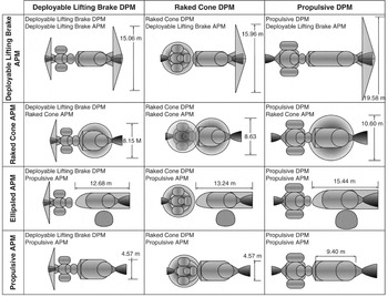
For this trade, four APM OTV configurations are explored: (1) deployable, (2) raked cone, (3) ellipsled and (4) pure propulsive. The Ellipsled AOTV is re-introduced in this study because the increased propellant volume of LH2 and staging of payload (DPM) prior to the aeropass does reduce the ballistic coefficient and increases the body radii relative to the crew DPM from the expendable APM trade. Each APM is sized for each DPM possibility as discussed in the previous section, leaving 12 total system configurations sized (4 APM × 3 DPM). Table 8 and Fig. 19 summarise the results.
Table 8 Design Mass Summary for APM+DPM OTVs – Re-usable APM


Figure 19. Geometry summary of OTV DPM+APM concepts – re-usable APM.
When comparing the dry, propellant and gross masses of the total APM+DPM system, it is clear that the primary driver for the AOTV DPM is the reduced total propellant mass, with the secondary driver being the APM concept (see Fig. 20). The selection of a deployable or raked cone DPM results in a propellant reduction of roughly 50% to 60% relative to the all propulsive systems, while the selection of the APM is only having a 10% to 20% effect on the total propellant mass over its corresponding all-propulsive concept.

Figure 20. Comparison of 12 AOTV DPM+APM concepts relative to propulsive DPM+APM.
The re-usable APM and DPM variation from CONOP 2 show that the deployable or raked cone DPM concepts will provide similar propellant mass, while the raked cone dry mass is 10% heavier due to the rigid structure and higher ballistic coefficient. The APM can certainly benefit from an AOTV concept. However, the selection between AOTV concepts must come from metrics other than mass alone. From this standpoint, all AOTV APM and DPM concepts could provide an operational benefit with a sufficiently high flight rate and low maintenance costs. Such cost comparison is beyond the scope of this study, but is required for realistic comparison between re-usable and expendable crew transfer architectures.
5.3.4 Summary of results and recommendations for CONOP 2
In the context of the expendable APM trade, deployable and raked cone aerobrake concepts show promise for reducing propellant mass in the crew return vehicle for return from GEO-0 to LEO-KSC, while the minimum diameter raked cone and ellipsled concepts present a re-usable TPS material problem due to their high ballistic coefficient and small radii.
For the re-usable APM branch of this CONOP, all APM concepts are sized for LEO-GTO transfer with a deployable DPM. The staging of the DPM results in a significant reduction in mass at LEO circularisation. Thus, the pure propulsive OTV APM is not as severely penalised as the POTV DPM, which must return the space-based crew module. As such, use of an AOTV shows less mass-reduction potential in APMs than in DPMs. Since the ellipsled concept has a greater TPS wetted area relative to the deployable and raked cone concepts as well as increased volume required to store the LH2 propellant, this results in a significant increase in dry mass over the propulsive OTV. As a consequence, propellant savings over the baseline is reduced to only 7% for the ellipsled.
6.0 SUMMARY AND CONCLUSIONS
The results from the CONOP 1 (direct insertion/re-entry concept of operation) study show that a capsule plus de-orbit propulsion module designed for manned geostationary satellite servicing is technologically feasible and of a size comparable with past and proposed capsules. The currently available launch capability allows for a manned geostationary satellite servicing architecture under this concept of operations.
CONOP 2 (launch to low-earth orbit at Kennedy Space Center inclination angle with an orbital transfer to/from geostationary orbit) has two branches or scenarios: (1) expendable ascent propulsion module and (2) re-usable ascent propulsion module. In both branches, the aero-assisted orbital transfer vehicle ascent and de-orbit propulsion modules show significant propellant mass savings when compared to the pure-propulsive baseline. Additionally the combination of a deployable symmetric aerobrake de-orbit propulsion module with either a re-usable or expendable ascent propulsion module shows a savings in dry mass when compared to the pure propulsive case. This savings is maximised with the choice of an expendable ascent propulsion module and a deployable symmetric aerobrake, overall resulting in a 21% reduction in dry mass.
Both the minimum complexity mission architecture (CONOP 1) and the increased re-usability mission scenario (CONOP 2), result in a vehicle-technology combination that is feasible in the five- to ten-year time frame. The impetus of this study has not been to propose a full space infrastructure, but to find a mission-technology-vehicle coupling that can best fit into the context of a larger infrastructure. To that end, the CONOP 2 mission with an expendable ascent propulsion module and a deployable symmetric aerobrake de-orbit propulsion module serves as the most favorable mission-technology-vehicle combination for near-term geostationary satellite servicing.
ACKNOWLEDGEMENTS
This work was performed under a NIA contract in collaboration with NASA-DARPA. The authors would like to acknowledge contributions from Jeffrey Bowles and David Glass on TPS sizing collaboration, Jeff Cerro as NASA team leader, and Paul Czysz as a consultant for hypersonic vehicle design.