


Nomenclature
- ${A_i}$
-
wrinkle amplitude (mm)
-
$a$
-
inner circle radius of rigid elements (mm)
-
$b$
-
diameter of outer circle of rigid elements (mm)
-
${C_{ijkl}}$
-
elastic matrix of films
-
${D_{ijkl}}$
-
Eshelby tensor of thin films
-
$E$
-
elastic modulus of thin films (MPa)
-
$l$
-
distance from endpoint of rigid element to vertex of thin film (mm)
-
$R$
-
inner circle radius of thin film (mm)
-
${R_c}$
-
distance from rigid element to vertex of thin film (mm)
-
${R_{wi}}$
-
wrinkle radius (mm)
-
${T_i}$
-
tensile force (N)
-
$t$
-
thickness of the thin film (mm)
-
${w_i}$
-
wrinkle flexure function (mm)
-
$\alpha $
-
half inner corner of square thin film (deg)
-
$\beta $
-
angle between endpoint of rigid component and coordinate axis (deg)
-
${\varepsilon _{\theta c}}$
-
tensile strain in circumferential direction
-
${\varepsilon _{\theta w}}$
-
geometric strain
-
${\varepsilon _{\theta \rho }}$
-
tensile strain in radial direction
-
$\theta$
-
angle between any point on thin film and y-axis (deg)
-
${\lambda _i}$
-
half wavelength of thin films (mm)
-
$\nu $
-
Poisson’s ratio of thin films
-
$\rho $
-
distance of any point on thin film to top vertex of thin film (deg)
-
${\sigma _{ij}}$
-
total stress of thin film (MPa)
-
$\sigma _{ij}^0$
-
total stress of thin film (MPa)
-
${\sigma '_{\!\!ij}}$
-
stress of uniform thin film (MPa)
-
$\sigma _{ij}^c$
-
concentrated stress at vertex of rigid element (MPa)
-
${\sigma _\rho }$
-
radial stress acting on corner vertex of thin film under tension (MPa)


1.0 Introduction
Thin-film structures are widely used in flexible electronics and aerospace engineering because of their light weight and high storage ratios [Reference Chandra, Kumar, Chattopadhyaya, Chatterjee and Kumar1–Reference Luo, Xing, Kang, Zhan and Ming4]. Adding microstructures to thin-film structures, such as thin-film antenna structures in aerospace engineering, has drawn significant interest [Reference Huang, Feria and Kim5–Reference Wang, Tan, Du and Wan7]. When the boundary of a thin film is constrained because of the low bending stiffness of the film, the film experiences compressive stress under tension, which causes the film to wrinkle instead of deforming uniformly under the influence of compressive stress [Reference Luo, Jian, Niu, Ming and Kang8–Reference Luo, Zhan, Xing and Kang10]. Therefore, the wrinkling behaviour of thin films under compressive stress is of interest to researchers.
Tension field theory and stability theory remain the main analytical methods for studying the wrinkling behaviour of thin films [Reference Iwasa11, Reference Akita and Natori12]. In the tension field theory, it is assumed that the bending stiffness of the thin film is zero, and the wrinkle region in the thin film is predicted by calculating the minimum principal stress of the thin film; however, tension field theory cannot calculate the amplitude of wrinkles in thin films [Reference Pipkin13]. In stability theory, it is usually assumed that a thin film can withstand small amounts of compressive stress, and the wrinkling phenomenon is regarded as the buckling behaviour of the film. Through stability theory, characteristic parameters, such as the wrinkle wavelength and wrinkle amplitude of thin films, can be obtained [Reference Liu, Huang and Wang14–Reference Deng, Xu and Clarke18]. However, the influence of the microstructure on the nonuniform distribution of thin-film wrinkles has not received much attention. When there is a microstructure on the thin film, the interaction force between the microstructure and the thin film changes the stress distribution of the thin film. Under the interaction, the thin film undergoes local bending and forms local wrinkles, thus changing the wrinkle pattern of the thin film [Reference Li, Niu, Wu, Zhang, Luo and Zhang19–Reference Sun, Huang, Zhang and Meng22].
In this study, the wrinkling behaviour of nonuniform thin-film structures with rigid components was first observed through experiments and numerical simulations. By incorporating stability theory, the relationship between the wrinkling mode of nonuniform thin films and the size of the microstructures was established. In turn, after determining the wrinkling mode of nonuniform thin films based on a nonuniform thin-film stress analysis method proposed previously [Reference Sun, Huang, Zhang and Meng22], a stress equilibrium relationship was established by introducing perturbation stress and analysing the local wrinkle deformation caused by the microstructure and global wrinkle deformation caused by tensile force. A model for predicting the wrinkling of square films containing microstructures on the diagonal was developed, providing a new approach to controlling the nonuniform film wrinkling mode and predicting the wrinkling deformation.
2.0 Experimental observation
In this article, a square rigid element of $10 \times 10 \times 1{\rm{mm}}$
and a square polyimide thin film of
$10 \times 10 \times 1{\rm{mm}}$
and a square polyimide thin film of $300 \times 300 \times 0.025{\rm{mm}}$
were used, wherein the rigid element was symmetrically fixed on the diagonal of the thin film through an adhesive, as shown in Fig. 1. The material properties of polyimide film structure and square rigid elements are listed in Table 1. In the experiment, polyimide tape was used to fix the film vertex. A tension sensor was used to control the tension, and photogrammetry was used to measure the wrinkle deformation of the film. When
$300 \times 300 \times 0.025{\rm{mm}}$
were used, wherein the rigid element was symmetrically fixed on the diagonal of the thin film through an adhesive, as shown in Fig. 1. The material properties of polyimide film structure and square rigid elements are listed in Table 1. In the experiment, polyimide tape was used to fix the film vertex. A tension sensor was used to control the tension, and photogrammetry was used to measure the wrinkle deformation of the film. When ${T_1} = {T_2} = 30{\rm{N}}$
and the rigid element positions
${T_1} = {T_2} = 30{\rm{N}}$
and the rigid element positions ${R_c}$
are 30, 40, 50, and 60mm, the wrinkle pattern R is as shown in Fig. 2. When
${R_c}$
are 30, 40, 50, and 60mm, the wrinkle pattern R is as shown in Fig. 2. When ${T_1} = 5{\rm{N}}$
,
${T_1} = 5{\rm{N}}$
, ${T_2} = 20{\rm{N}}$
, and the rigid element positions
${T_2} = 20{\rm{N}}$
, and the rigid element positions ${R_c}$
are 30, 40, 50, and 60mm, the wrinkle pattern is as shown in Fig. 3. Figure 2 shows that the rigid element does not tilt with the wrinkle under uniform tension. Figure 3 reveals that the rigid element tilts with the wrinkle under nonuniform tension. Furthermore, Figs. 2 and 3 show that the appearance of the rigid element changes the wrinkle pattern, and the wrinkle amplitude is the smallest when the position of the rigid element
${R_c}$
are 30, 40, 50, and 60mm, the wrinkle pattern is as shown in Fig. 3. Figure 2 shows that the rigid element does not tilt with the wrinkle under uniform tension. Figure 3 reveals that the rigid element tilts with the wrinkle under nonuniform tension. Furthermore, Figs. 2 and 3 show that the appearance of the rigid element changes the wrinkle pattern, and the wrinkle amplitude is the smallest when the position of the rigid element ${R_c} = 50{\rm{mm}}$
. In previous studies, this phenomenon was investigated through stress analysis. However, this phenomenon provides a new idea for restraining and controlling thin-film wrinkles.
${R_c} = 50{\rm{mm}}$
. In previous studies, this phenomenon was investigated through stress analysis. However, this phenomenon provides a new idea for restraining and controlling thin-film wrinkles.
Figure 1. Structural diagram of nonuniformities of thin film with rigid elements.
3.0 Results and discussion
3.1 Effect of rigid elements on wrinkles patterns
The relationship between whether the rigid element inclines with a wrinkle and the size of the rigid element was analysed. For tension ${T_1} = {T_2}$
, an eigenvalue buckling analysis of the thin-film structure shown in Fig. 1 was conducted using ABAQUS finite-element analysis (FEA) software. The thin shell element S4R with four nodes and six degrees of freedom was used for the membrane structure, and the hexahedral element C3D8R with eight nodes and three degrees of freedom was used for the rigid element. All finite-element dimensions were 1 mm. The rigid element and membrane were connected by binding constraints. An eigenvalue buckling analysis can be used to determine the buckling mode of a thin film. The eigenvalue buckling results when the location of the rigid element
${T_1} = {T_2}$
, an eigenvalue buckling analysis of the thin-film structure shown in Fig. 1 was conducted using ABAQUS finite-element analysis (FEA) software. The thin shell element S4R with four nodes and six degrees of freedom was used for the membrane structure, and the hexahedral element C3D8R with eight nodes and three degrees of freedom was used for the rigid element. All finite-element dimensions were 1 mm. The rigid element and membrane were connected by binding constraints. An eigenvalue buckling analysis can be used to determine the buckling mode of a thin film. The eigenvalue buckling results when the location of the rigid element ${R_c} = 30\;{\rm{mm}}$
are shown in Fig. 4.
${R_c} = 30\;{\rm{mm}}$
are shown in Fig. 4.
Through eigenvalue buckling analysis, two buckling modes can be obtained. When rigid elements are present on the thin film, it can have two different modes of wrinkling. The rigid elements in mode 1 are inclined with the appearance of wrinkles, and the rigid elements in mode 2 are not inclined with the appearance of wrinkles. This result is consistent with the experimental results shown in Figs. 2 and 3. Therefore, the wrinkle mode of the nonuniform thin-film structure of rigid elements is mainly determined by the relationship between the radius of the circumscribed circle of the rigid element and the wrinkle wavelength. In other words, when the wrinkle half-wavelength $d \lt 2{\lambda _1}$
, the wrinkle mode of the film is consistent with mode 1; when the wrinkle half-wavelength
$d \lt 2{\lambda _1}$
, the wrinkle mode of the film is consistent with mode 1; when the wrinkle half-wavelength $d \geqslant 2{\lambda _2}$
, the wrinkle mode of the thin film is consistent with the mode 2. The wavelength
$d \geqslant 2{\lambda _2}$
, the wrinkle mode of the thin film is consistent with the mode 2. The wavelength ${\rm{\lambda }}$
of the thin-film structure can be expressed as [Reference Bonin16]
${\rm{\lambda }}$
of the thin-film structure can be expressed as [Reference Bonin16]
 \begin{align}\lambda = {\left[ {\frac{{E{\pi ^2}{t^2}{R_w}^2}}{{12\!\left( {1 - {\nu ^2}} \right)\!{\sigma _\rho }}}} \right]^{\frac{1}{4}}}\end{align}
where E is the elastic modulus of the thin film, v is Poisson’s ratio of the thin film, t is the thickness of the thin film, and ${\sigma _\rho }$
is the radial stress of the nonuniform thin film. At the thin-film boundary, the influence of the disturbance stress of the rigid element on the thin-film stress field can be ignored. At this point, the radial stress of the nonuniform thin film is consistent with the radial stress of the uniform thin film, which can be expressed as
${\sigma _\rho }$
is the radial stress of the nonuniform thin film. At the thin-film boundary, the influence of the disturbance stress of the rigid element on the thin-film stress field can be ignored. At this point, the radial stress of the nonuniform thin film is consistent with the radial stress of the uniform thin film, which can be expressed as
 \begin{align}{\sigma _\rho } = \frac{{4T\cos \theta }}{{\!\left( {\pi + 2} \right)\!\rho t}}\end{align}
Table 1. Material parameters of thin film and rigid elements
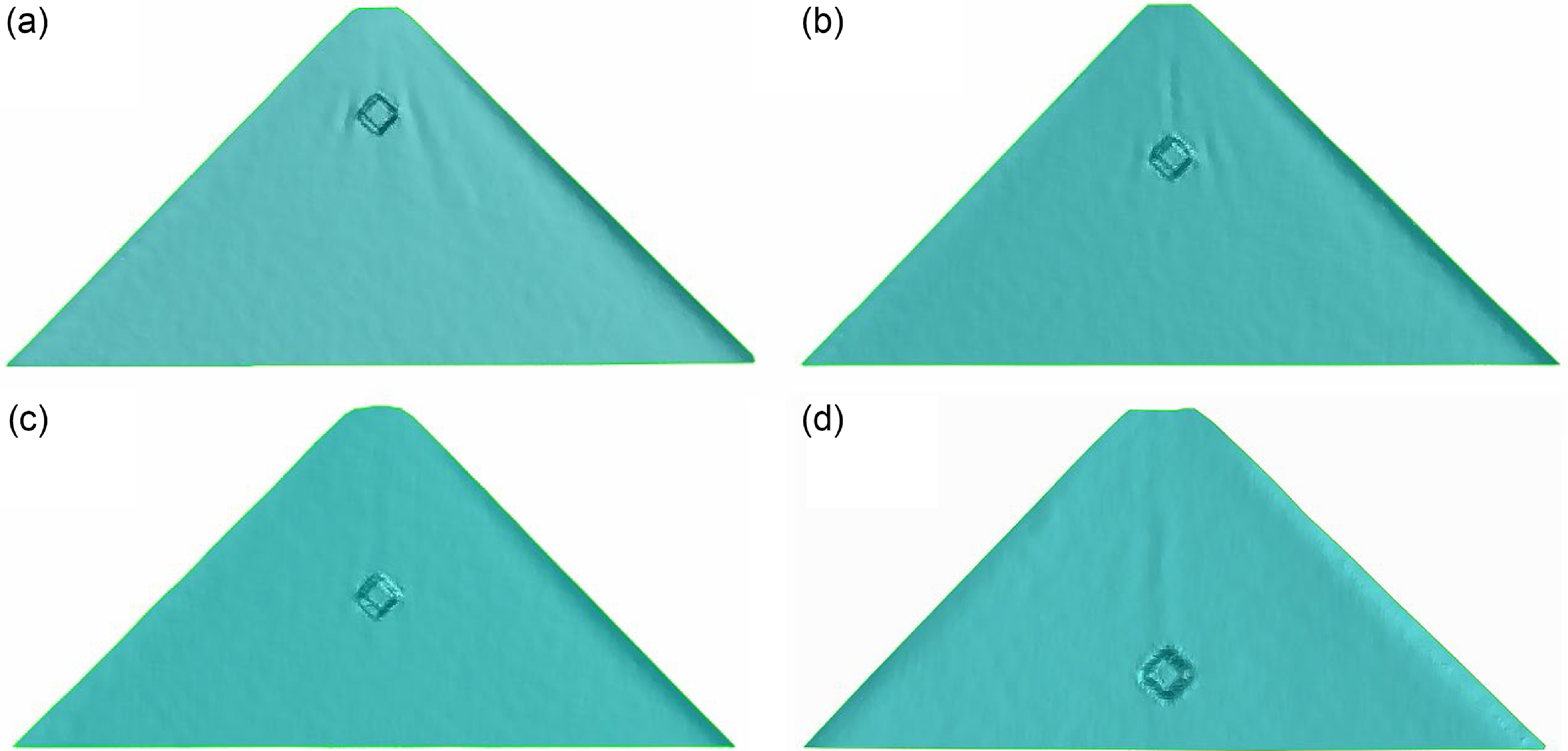
Figure 2. Wrinkling patterns of rigid element at different locations under uniform tension: (a)–(d) show positions Rc of the rigid elements of 30, 40, 50, and 60mm, respectively.
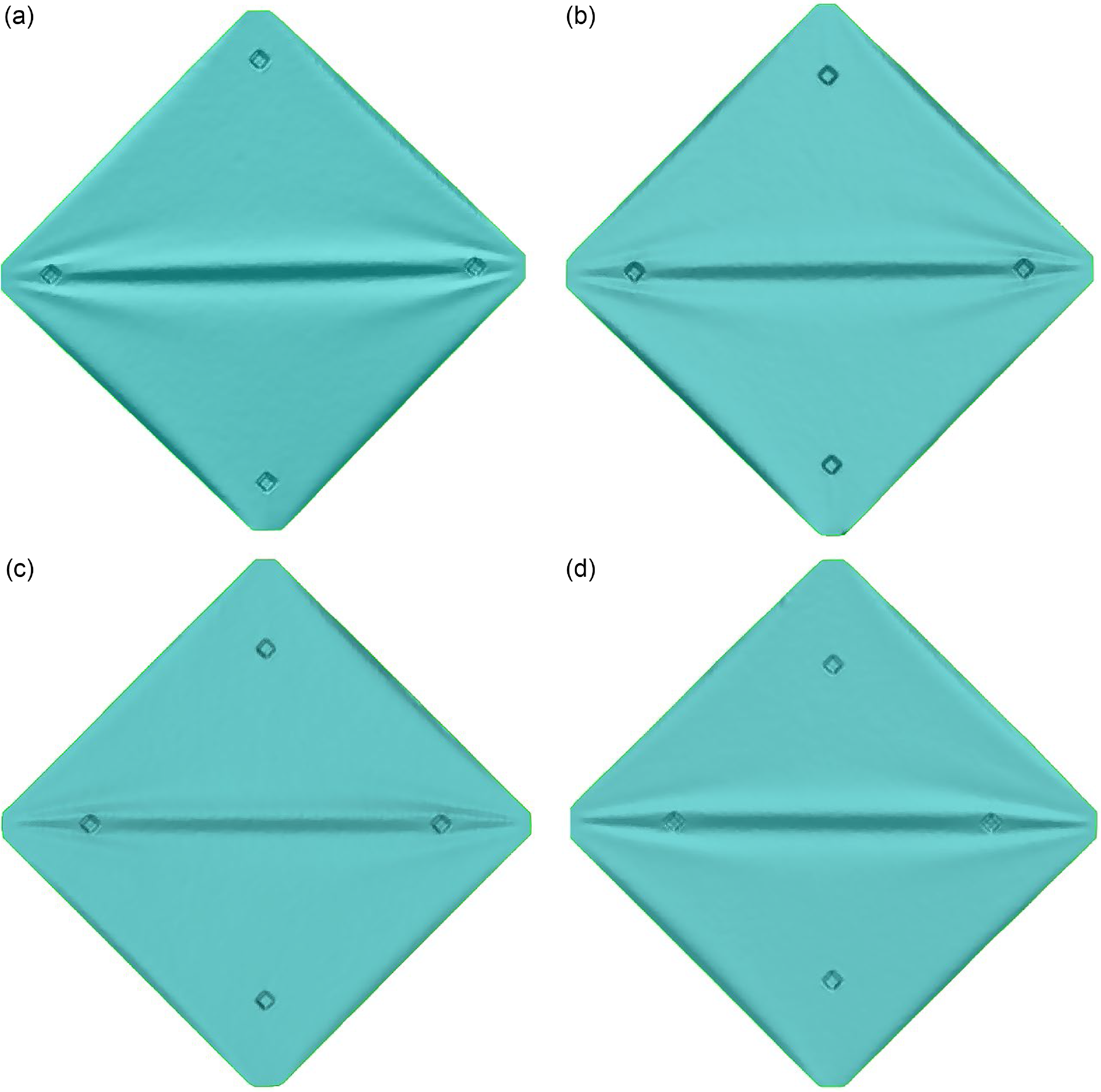
Figure 3. Wrinkling patterns of rigid element at different locations under nonuniform tension: (a)–(d) show positions Rc of the rigid elements of 30, 40, 50, and 60mm, respectively.
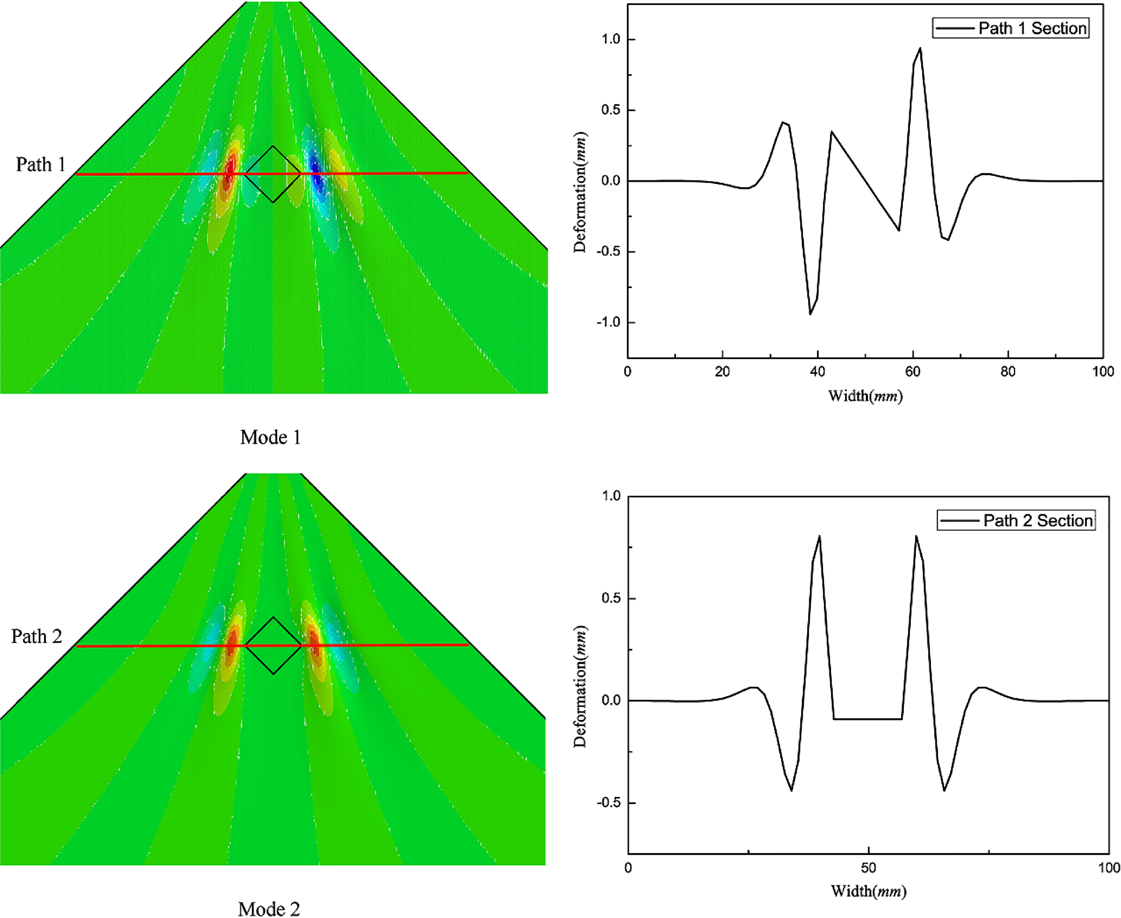
Figure 4. Eigenvalue buckling analysis of thin-film structures with rigid elements.
Here, ${R_w}$
is the radius of the wrinkled region in the thin film. The boundary region of the thin film can be obtained [Reference Bonin16] as
${R_w}$
is the radius of the wrinkled region in the thin film. The boundary region of the thin film can be obtained [Reference Bonin16] as
 \begin{align}{R_w} = {e^{ - v}}R\end{align}
According to the experimental observations, when ${T_1}/{T_2} = 4$
, wrinkles occur across the diagonal region of the thin film. Therefore, the tension ratio is defined as
${T_1}/{T_2} = 4$
, wrinkles occur across the diagonal region of the thin film. Therefore, the tension ratio is defined as ${\rm{c}} = {T_1}/{T_2}$
. When the wrinkle pattern is shown in mode 2, the global wrinkle radius
${\rm{c}} = {T_1}/{T_2}$
. When the wrinkle pattern is shown in mode 2, the global wrinkle radius ${R_{w1}}$
and local wrinkle radius
${R_{w1}}$
and local wrinkle radius ${R_{w2}}$
can be expressed as
${R_{w2}}$
can be expressed as
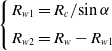 \begin{align}\left\{ \begin{array}{l@{\quad}l} {{R_{w1}} = {{{R_c}} / {\sin \alpha }}} \\[5pt] {{R_{w2}} = {R_w} - {R_{w1}}} \end{array} \right.\end{align}
Here, ${{\rm{\lambda }}_1}$
is the first half-wavelength close to the central line and can be expressed as
${{\rm{\lambda }}_1}$
is the first half-wavelength close to the central line and can be expressed as
 \begin{align}{\lambda _1} = \left( {\frac{{{R_c}}}{{\sin \alpha }} + \frac{d}{2}} \right)\!\tan \!\left( {\frac{\alpha }{n}} \right)\end{align}
The wrinkling number n of the thin film can be expressed as
 \begin{align}n = \frac{{\alpha {R_w}}}{\lambda }\end{align}
At this time, one can obtain the relationship between the side length and the wrinkle mode when the position of the rigid element ${R_c} = 30\;{\rm{mm}}$
, as shown in Fig. 5. Figure 3 reveals that, when the position of the rigid element
${R_c} = 30\;{\rm{mm}}$
, as shown in Fig. 5. Figure 3 reveals that, when the position of the rigid element ${R_c} = 30\;{\rm{mm}}$
, the side length of the rigid element
${R_c} = 30\;{\rm{mm}}$
, the side length of the rigid element $2a = 10\;{\rm{mm}}$
, and
$2a = 10\;{\rm{mm}}$
, and ${T_1} = {T_2}$
, the wrinkle mode of the nonuniform thin film is mode 2 – that is, the rigid element does not tilt with the appearance of wrinkles.
${T_1} = {T_2}$
, the wrinkle mode of the nonuniform thin film is mode 2 – that is, the rigid element does not tilt with the appearance of wrinkles.
Figure 5. Relationship between side length of rigid element and wrinkled mode.
3.2 Wrinkle model when rigid element is inclined with the wrinkle
The experimental results in Fig. 2 show that, when the diameter of the circumscribed circle of the rigid element is $\;d \geqslant 2{\lambda _1}$
, the wrinkle mode of the nonuniform thin film is mode 2. To describe the wrinkle pattern in mode 2, the wrinkle configuration function w on a nonuniform thin film can be expressed as
$\;d \geqslant 2{\lambda _1}$
, the wrinkle mode of the nonuniform thin film is mode 2. To describe the wrinkle pattern in mode 2, the wrinkle configuration function w on a nonuniform thin film can be expressed as
 \begin{align}w = \sum\limits_{i = 1}^4 {\left( {{w_{i1}} + {w_{i2}}} \right)} \end{align}
According to thin-film stability theory, the local wrinkle configuration function ${w_{i1}}$
and the global wrinkle configuration function
${w_{i1}}$
and the global wrinkle configuration function ${w_{i2}}$
can be expressed as
${w_{i2}}$
can be expressed as
 \begin{align}\begin{array}{l}{w_{i1}} = {A_{i1}}\sin\!\left( {\dfrac{{\pi \rho }}{{{c^{{{\left( { - 1} \right)}^i}}}{R_{w1}}}}} \right)\!\sin\!\left( {\dfrac{{\pi \theta }}{\lambda }} \right)\\[10pt] {w_{i2}} = {A_{i2}}\sin\!\left[ {\dfrac{{\pi \!\left( {\rho - l + \dfrac{{{R_{w2}}}}{2}} \right)}}{{{R_{w2}}}}} \right]\!\sin\!\left[ {\dfrac{{\pi \left( {\theta - \beta } \right)}}{\lambda }} \right]\end{array}\end{align}
The geometric strain ${\varepsilon _{\theta w}}$
in the wrinkle direction can be expressed as
${\varepsilon _{\theta w}}$
in the wrinkle direction can be expressed as
 \begin{align}{\varepsilon _{\theta w}} = {\varepsilon _{\theta c}} - {\varepsilon _{\theta \rho }} = - \frac{{{A^2}{\pi ^2}}}{{4{\lambda ^2}}}\end{align}
where ${\varepsilon _{\theta \rho }}$
and
${\varepsilon _{\theta \rho }}$
and ${\varepsilon _{\theta c}}$
are the tensile strain in the radial direction and the shrinkage strain in the circumferential direction, respectively, and can be expressed as
${\varepsilon _{\theta c}}$
are the tensile strain in the radial direction and the shrinkage strain in the circumferential direction, respectively, and can be expressed as
 \begin{align}{\varepsilon _{\theta \rho }} = - \nu \frac{{{\sigma _\rho }}}{E}{\rm{ }}\end{align}
 \begin{align}{\varepsilon _{\theta c}} = \frac{{\int {\frac{{{\sigma _\rho }}}{E}dy} }}{y}\end{align}
Equations (10) and (11) can be substituted into Equation (9) to obtain the wrinkle amplitude $A\!\left( {\rho, \theta } \right)$
of the thin film:
$A\!\left( {\rho, \theta } \right)$
of the thin film:
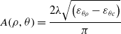 \begin{align}A\!\left( {\rho, \theta } \right) = \frac{{2\lambda \sqrt {\left( {{\varepsilon _{\theta \rho }} - {\varepsilon _{\theta c}}} \right)} }}{\pi }\end{align}
The strain field of a nonuniform thin film can be calculated using Eshelby’s elastic inclusion theory. According to previous research [Reference Li, Niu, Wu, Zhang, Luo and Zhang19], the stress distribution in thin films with rigid inclusions can be expressed as
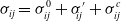 \begin{align}{\sigma _{ij}} = \sigma _{ij}^0 + {\sigma '_{\!\!ij}} + \sigma _{ij}^c\end{align}
where $\sigma _{ij}^0$
is the stress of the uniform thin film,
$\sigma _{ij}^0$
is the stress of the uniform thin film, $\sigma _{ij}{\prime}$
is the disturbance stress caused by the rigid element, and
$\sigma _{ij}{\prime}$
is the disturbance stress caused by the rigid element, and $\sigma _{ij}^c$
is the concentrated stress at the corners of the rigid element, which are respectively expressed as [Reference Sun, Huang, Zhang and Meng22]
$\sigma _{ij}^c$
is the concentrated stress at the corners of the rigid element, which are respectively expressed as [Reference Sun, Huang, Zhang and Meng22]
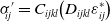 \begin{align}{\sigma '_{\!\!ij}} = {C_{ijkl}}\!\left( {{D_{ijkl}}\varepsilon _{ij}^ * } \right)\end{align}
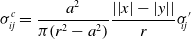 \begin{align}\sigma _{ij}^c = \frac{{{a^2}}}{{\pi \!\left( {{r^2} - {a^2}} \right)}}\frac{{\left| {\left| x \right| - \left| y \right|} \right|}}{r}{\sigma '_{\!\!ij}}\end{align}
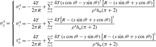 \begin{align}\sigma _{ij}^0 = \left\{ {\begin{array}{l}{\sigma _x^0 = - \dfrac{{4T}}{{2\pi R}} + \sum\limits_{i = 1}^{i = 4} {\dfrac{{4T{{\left( {x\cos i\theta - y\sin i\theta } \right)}^2}\left[ {R - \left( {x\sin i\theta + y\cos i\theta } \right)} \right]}}{{{\rho ^4}{h_m}(\pi + 2)}}} }\\[12pt] {\sigma _y^0 = - \dfrac{{4T}}{{2\pi R}} + \sum\limits_{i = 1}^{i = 4} {\dfrac{{4T{{\left[ {R - \left( {x\sin i\theta + y\cos i\theta } \right)} \right]}^3}}}{{{\rho ^4}{h_m}(\pi + 2)}}{\rm{ }}} }\\[12pt] {\tau _{xy}^0 = - \dfrac{{4T}}{{2\pi R}} + \sum\limits_{i = 1}^{i = 4} {\dfrac{{4T\left( {x\cos i\theta - y\sin i\theta } \right){{\left[ {R - \left( {x\sin i\theta + y\cos i\theta } \right)} \right]}^2}}}{{{\rho ^4}{h_m}(\pi + 2)}}} }\end{array}} \right.\end{align}
Here, ${C_{ijkl}}$
is the elastic matrix of the film,
${C_{ijkl}}$
is the elastic matrix of the film, $\varepsilon _{ij}^*$
is the characteristic strain of the film, and
$\varepsilon _{ij}^*$
is the characteristic strain of the film, and ${D_{ijkl}}$
is the Eshelby external tensor, which can be expressed as [Reference Sun, Huang, Zhang and Meng22]
${D_{ijkl}}$
is the Eshelby external tensor, which can be expressed as [Reference Sun, Huang, Zhang and Meng22]
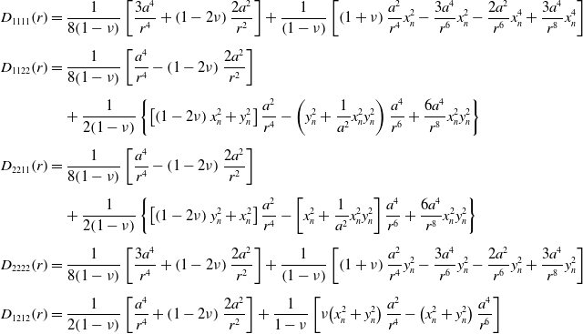 \begin{align} {D_{1111}}\!\left( r \right) &= \frac{1}{{8\!\left( {1 - \nu } \right)}}\left[ {\frac{{3{a^4}}}{{{r^4}}} + \left( {1 - 2\nu } \right)\frac{{2{a^2}}}{{{r^2}}}} \right] + \frac{1}{{\left( {1 - \nu } \right)}}\left[ {\left( {1 + \nu } \right)\frac{{{a^2}}}{{{r^4}}}x_n^2 - \frac{{3{a^4}}}{{{r^6}}}x_n^2 - \frac{{2{a^2}}}{{{r^6}}}x_n^4 + \frac{{3{a^4}}}{{{r^8}}}x_n^4} \right]\nonumber \\[5pt] {D_{1122}}\!\left( r \right) &= \frac{1}{{8\!\left( {1 - \nu } \right)}}\left[ {\frac{{{a^4}}}{{{r^4}}} - \left( {1 - 2\nu } \right)\frac{{2{a^2}}}{{{r^2}}}} \right]\nonumber \\[5pt] & \quad + \frac{1}{{2\!\left( {1 - \nu } \right)}}\left\{ {\left[ {\left( {1 - 2\nu } \right)x_n^2 + y_n^2} \right]\frac{{{a^2}}}{{{r^4}}} - \left( {y_n^2 + \frac{1}{{{a^2}}}x_n^2y_n^2} \right)\frac{{{a^4}}}{{{r^6}}} + \frac{{6{a^4}}}{{{r^8}}}x_n^2y_n^2} \right\}\nonumber\\[5pt] {D_{2211}}\!\left( r \right) &= \frac{1}{{8\!\left( {1 - \nu } \right)}}\left[ {\frac{{{a^4}}}{{{r^4}}} - \left( {1 - 2\nu } \right)\frac{{2{a^2}}}{{{r^2}}}} \right]\nonumber \\[5pt] & \quad + \frac{1}{{2\!\left( {1 - \nu } \right)}}\left\{ {\left[ {\left( {1 - 2\nu } \right)y_n^2 + x_n^2} \right]\frac{{{a^2}}}{{{r^4}}} - \left[ {x_n^2 + \frac{1}{{{a^2}}}x_n^2y_n^2} \right]\frac{{{a^4}}}{{{r^6}}} + \frac{{6{a^4}}}{{{r^8}}}x_n^2y_n^2} \right\}\nonumber\\[5pt] {D_{2222}}\!\left( r \right) &= \frac{1}{{8\!\left( {1 - \nu } \right)}}\left[ {\frac{{3{a^4}}}{{{r^4}}} + \left( {1 - 2\nu } \right)\frac{{2{a^2}}}{{{r^2}}}} \right] + \frac{1}{{\left( {1 - \nu } \right)}}\left[ {\left( {1 + \nu } \right)\frac{{{a^2}}}{{{r^4}}}y_n^2 - \frac{{3{a^4}}}{{{r^6}}}y_n^2 - \frac{{2{a^2}}}{{{r^6}}}y_n^2 + \frac{{3{a^4}}}{{{r^8}}}y_n^2} \right]\nonumber\\[5pt] {D_{1212}}\!\left( r \right) &= \frac{1}{{2\!\left( {1 - \nu } \right)}}\left[ {\frac{{{a^4}}}{{{r^4}}} + \left( {1 - 2\nu } \right)\frac{{2{a^2}}}{{{r^2}}}} \right] + \frac{1}{{1 - \nu }}\left[ {\nu\!\left( {x_n^2 + y_n^2} \right)\frac{{{a^2}}}{{{r^4}}} - \left( {x_n^2 + y_n^2} \right)\frac{{{a^4}}}{{{r^6}}}} \right] \end{align}
When $\rho = {R_{w1}}/2$
and
$\rho = {R_{w1}}/2$
and $\theta = 0$
, an exponential function obtained through finite-element analysis is introduced to modify the wrinkle amplitude, and the maximum amplitude
$\theta = 0$
, an exponential function obtained through finite-element analysis is introduced to modify the wrinkle amplitude, and the maximum amplitude ${A_{i1}}$
of the global wrinkle configuration function w is obtained as
${A_{i1}}$
of the global wrinkle configuration function w is obtained as
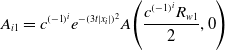 \begin{align}{A_{i1}} = {c^{{{\left( { - 1} \right)}^i}}}{e^{ - {{\left( {3t\left| {{x_i}} \right|} \right)}^2}}}A\!\left( {\frac{{{c^{{{\left( { - 1} \right)}^i}}}{R_{w1}}}}{2},0} \right)\end{align}
Because the rigid element on the thin film changes the original stress field of the thin film, local wrinkles caused by the disturbance stress of the rigid element appear on both sides of the thin film, and the amplitude of the wrinkles is the largest at the apex of the rigid element. When $\rho = l$
and
$\rho = l$
and ${\rm{\;}}\rho = l$
, the maximum amplitude
${\rm{\;}}\rho = l$
, the maximum amplitude ${A_{i2}}$
of the local wrinkle configuration function w caused by the rigid element is
${A_{i2}}$
of the local wrinkle configuration function w caused by the rigid element is
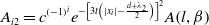 \begin{align}{A_{i2}} = {c^{{{\left( { - 1} \right)}^i}}}{e^{ - {{\left[ {3t\left(\left| {{x_i}} \right| - \frac{{d + {\lambda _2}}}{2}\right)} \right]}^2}}}A\!\left( {l,\beta } \right)\end{align}
where ${\lambda _2}$
is the half-wavelength of the first wrinkle outside the rigid element, which can be expressed as
${\lambda _2}$
is the half-wavelength of the first wrinkle outside the rigid element, which can be expressed as
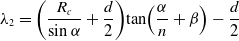 \begin{align}{\lambda _2} = \left( {\frac{{{R_c}}}{{\sin \alpha }} + \frac{d}{2}} \right)\!\tan \!\left( {\frac{\alpha }{n} + \beta } \right) - \frac{d}{2}\end{align}
By substituting Equations (18) and (19) into Equation (8), the wrinkle configuration function of the nonuniform thin-film structure of rigid elements corresponding to mode 1 can be obtained. When the rigid element is large, the wrinkle shape shown in mode 1 mostly appears in the case of uniform tension. Therefore, taking uniform stretching as an example, when the distance between the rigid elements ${R_c} = 30{\rm{mm}}$
and tension
${R_c} = 30{\rm{mm}}$
and tension ${T_1} = {T_2} = 30{\rm{N}}$
, the wrinkle distribution diagrams obtained through the stretching experiment, finite-element simulation, and theoretical analysis are as shown in Fig. 6. The out-of-plane deformation in the path 1 cross section is also shown in Fig. 6.
${T_1} = {T_2} = 30{\rm{N}}$
, the wrinkle distribution diagrams obtained through the stretching experiment, finite-element simulation, and theoretical analysis are as shown in Fig. 6. The out-of-plane deformation in the path 1 cross section is also shown in Fig. 6.
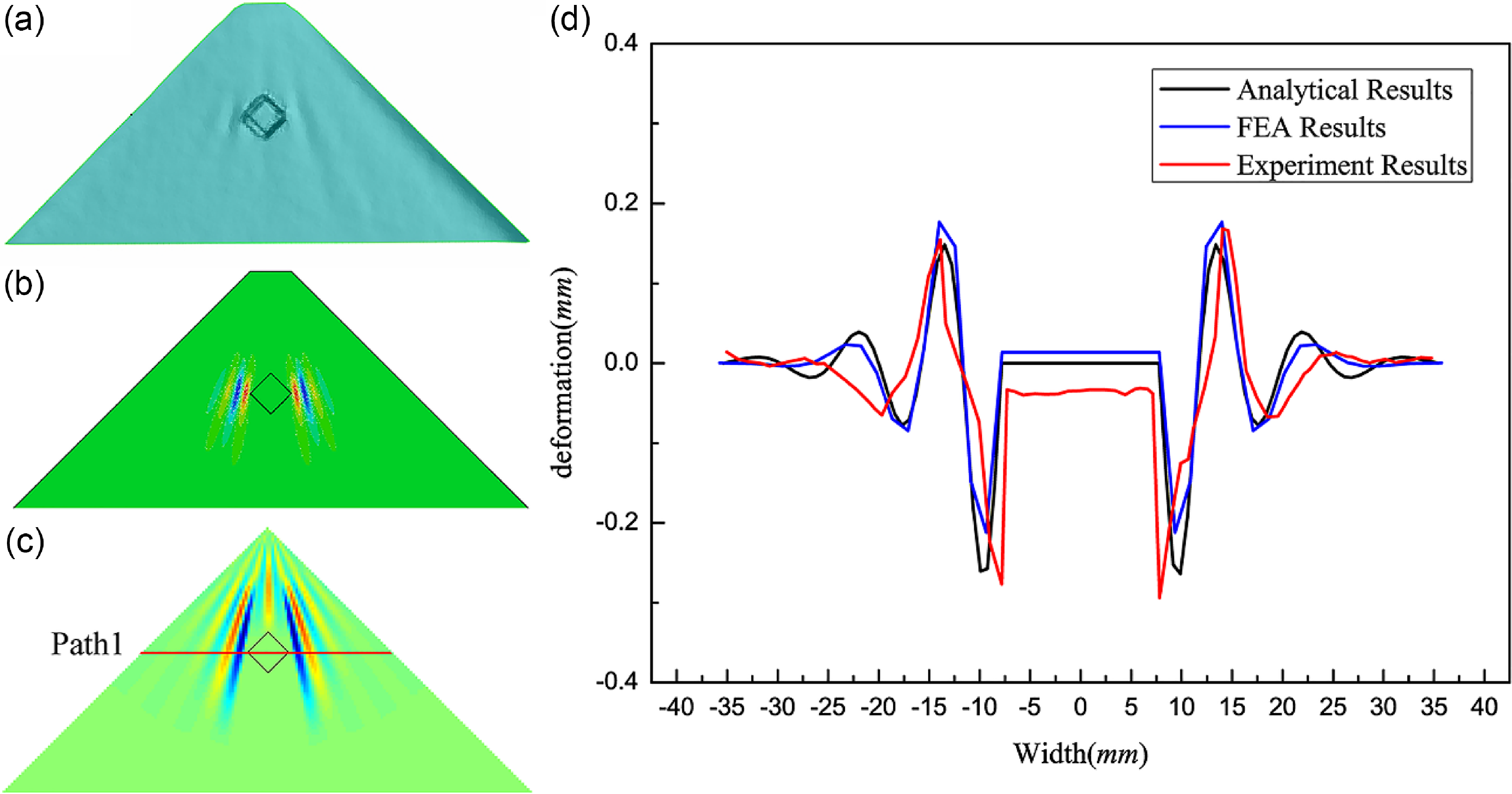
Figure 6. Wrinkle shapes and out-of-plane deformation in the path cross section: (a) is the experimental result, (b) is the FEA result, (c) is the analytical result, and (d) is the out-of-plane deformation in the path 1 cross section.
3.3 Wrinkle model when the rigid element does not incline with the wrinkle
When the circumscribed circle diameter of the rigid element $d \lt 2{\lambda _1}$
, the wrinkle pattern of the nonuniform thin film is mode 1, and the rigid element tilts with the appearance of the wrinkle. Therefore, to describe the wrinkle morphology shown in mode 1, the wrinkle configuration function w of the nonuniform film can be expressed as
$d \lt 2{\lambda _1}$
, the wrinkle pattern of the nonuniform thin film is mode 1, and the rigid element tilts with the appearance of the wrinkle. Therefore, to describe the wrinkle morphology shown in mode 1, the wrinkle configuration function w of the nonuniform film can be expressed as
 \begin{align}w = \sum\limits_{i = 1}^4 {\left( {{w_{i1}} + {w_{i2}}} \right)} \end{align}
where ${w_{i1}}$
is the local wrinkle configuration caused by rigid elements, and
${w_{i1}}$
is the local wrinkle configuration caused by rigid elements, and ${w_{i2}}$
is the global wrinkle configuration. According to thin-film stability theory, wrinkles
${w_{i2}}$
is the global wrinkle configuration. According to thin-film stability theory, wrinkles ${w_{i1}}$
and
${w_{i1}}$
and ${w_{i2}}$
can be expressed as
${w_{i2}}$
can be expressed as
 \begin{align} {w_{i1}} &= {A_{i1}}\sin\!\left( {\frac{{\pi \rho }}{{{c^{{{\left( { - 1} \right)}^i}}}{R_w}}}} \right)\!\cos\! \left( {\frac{{\pi \theta }}{\lambda }} \right)\nonumber \\[5pt] {w_{i2}} &= {A_{i2}}\sin\!\left[ {\frac{{\pi \!\left( {\rho - l} \right)}}{{{R_{w2}}}}} \right]\!\cos\! \left[ {\frac{{\pi \!\left( {\theta - \beta } \right)}}{\lambda }} \right] \end{align}
When $\rho = {c^{{{\left( { - 1} \right)}^i}}}/2$
and
$\rho = {c^{{{\left( { - 1} \right)}^i}}}/2$
and $\theta = 0$
, the maximum amplitude A of the local wrinkle configuration function w caused by the rigid element is
$\theta = 0$
, the maximum amplitude A of the local wrinkle configuration function w caused by the rigid element is
 \begin{align}{A_{i1}} = {c^{{{\left( { - 1} \right)}^i}}}{e^{ - {{\left[ {3t\left( {\left| {{x_i}} \right| - \frac{{{\lambda _2}}}{2}} \right)} \right]}^2}}}A\!\left( {\frac{{{c^{{{\left( { - 1} \right)}^i}}}{R_{w1}}}}{2},0} \right)\end{align}
When $\rho = l$
and
$\rho = l$
and $\theta = \beta $
, the maximum amplitude A of the local wrinkle configuration function w caused by the rigid element is
$\theta = \beta $
, the maximum amplitude A of the local wrinkle configuration function w caused by the rigid element is
 \begin{align}{A_{i2}} = {e^{ - {{\left[ {3t\left(\left| {{x_i}} \right| - \frac{{2{\lambda _1} + {\lambda _2}}}{2}\right)} \right]}^2}}}A\!\left( {l,\beta } \right)\end{align}
When $i$
is odd,
$i$
is odd, ${x_i} = x$
. When
${x_i} = x$
. When $i$
is even,
$i$
is even, ${\rm{\;}}{x_i} = y$
. By substituting Equations (23) and (24) into Equation (22), the wrinkle configuration function of the nonuniform thin-film structure of rigid elements corresponding to mode 2 can be obtained. The slope of the rigid element can be obtained by substituting the coordinates of the endpoint of the rigid element into Equation (22). The wrinkle pattern shown in mode 1 is prone to occur in the case of nonuniform stretching or small rigid elements. Therefore, taking nonuniform stretching as an example, when the rigid element distance
${\rm{\;}}{x_i} = y$
. By substituting Equations (23) and (24) into Equation (22), the wrinkle configuration function of the nonuniform thin-film structure of rigid elements corresponding to mode 2 can be obtained. The slope of the rigid element can be obtained by substituting the coordinates of the endpoint of the rigid element into Equation (22). The wrinkle pattern shown in mode 1 is prone to occur in the case of nonuniform stretching or small rigid elements. Therefore, taking nonuniform stretching as an example, when the rigid element distance ${R_c} = 30$
and the tensile forces
${R_c} = 30$
and the tensile forces ${T_1} = 5{\rm{N}}$
and
${T_1} = 5{\rm{N}}$
and ${T_2} = 20{\rm{N}}$
, the wrinkle distribution diagrams obtained by the experiment, finite-element simulation, and theoretical analysis are as shown in Fig. 7. The out-of-plane deformations in the path 1 and 2 cross sections are shown in Fig. 7.
${T_2} = 20{\rm{N}}$
, the wrinkle distribution diagrams obtained by the experiment, finite-element simulation, and theoretical analysis are as shown in Fig. 7. The out-of-plane deformations in the path 1 and 2 cross sections are shown in Fig. 7.
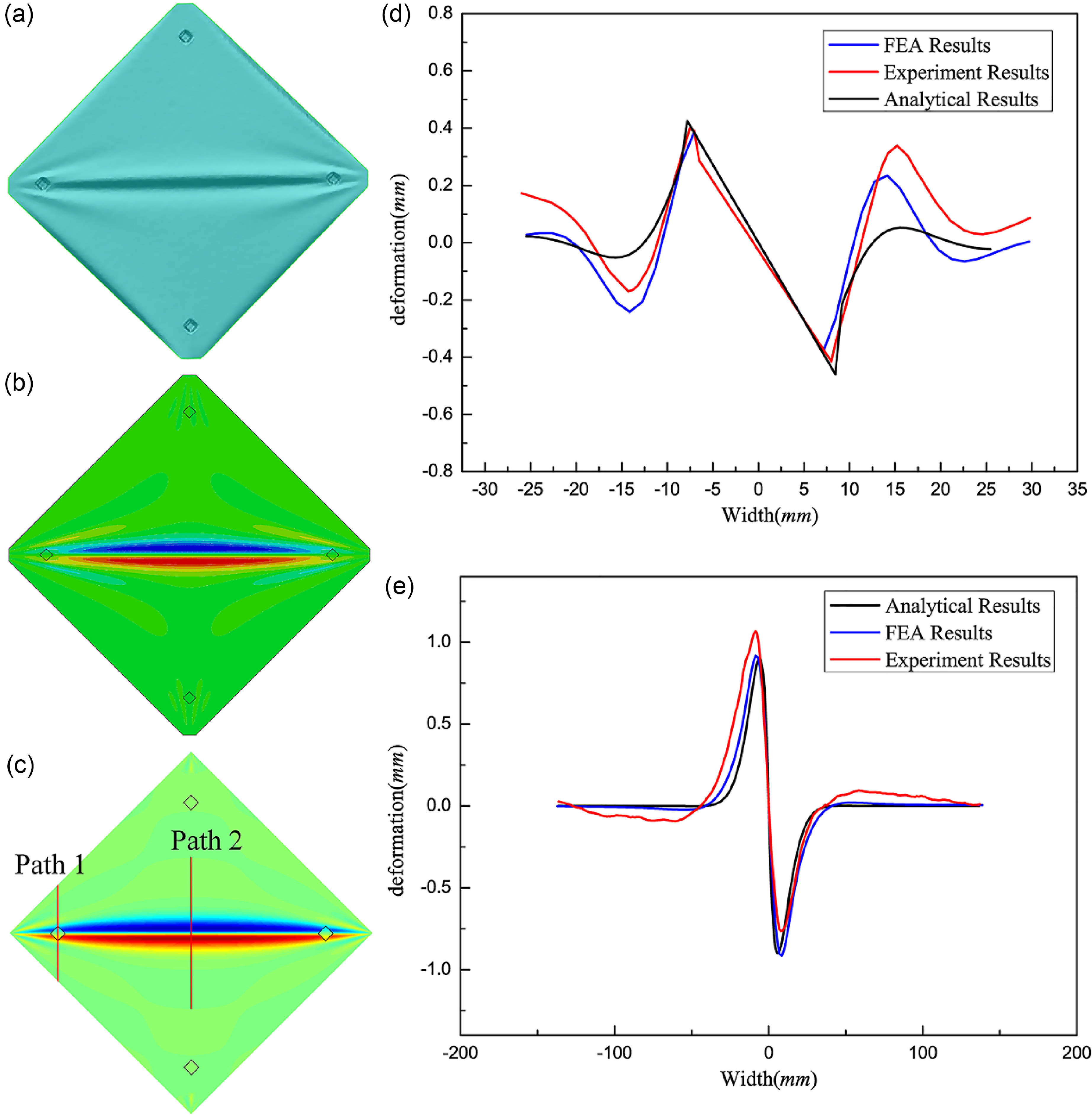
Figure 7. Wrinkle shapes and out-of-plane deformation in the path cross section: (a) is the experimental result, (b) is the FEA result, (c) is the analytical result, (d) is the out-of-plane deformation in the path 1 cross section, and (e) is the out-of-plane deformation in the path 2 cross section.
4.0 Conclusion
A tensile square thin-film wrinkle model with a rigid element located on the diagonal line was constructed, and the relationship between the shape and size of the rigid element was analysed by experimental observation and finite-element simulation. A nonuniform stress field was introduced to superimpose the local folds caused by the disturbance stress of the rigid element and the global folds of the thin film. Compared with the finite-element analysis, the proposed model is easier to solve and does not lead to divergent results, which provides a new approach to the wrinkle analysis of nonuniform thin films with microstructures.
Acknowledgement
This work was supported in part by the National Natural Science Foundation of China under Grant 52035010, in part by the Shaanxi Innovation Team Project under Grant 2018TD-012, in part by the Shaanxi Key Industry Chain Project under Grant 2020ZDLGY14-08, in part by the National 111 Project under Grant B14042, in part by the Shaanxi Provincial Fund under Grant 2022JQ-366. in part by the National Natural Science Foundation of China under Grant 52205411, in part by the National Key Laboratory Fund under Grant 2022-JCJQ-LB-018, and in part by the National Natural Science Foundation of China under Grant 52275372. We would like to thank Editage (www.editage.cn) for English language editing.
Author contributions
All authors contributed to the conception and design of this study. Material preparation, data collection and analysis were performed by Peng Sun, Jin Huang, Jiaying Zhang, Fanbo Meng and Pengbing Zhao. The first draft of the manuscript was written by Peng Sun, and all authors commented on previous versions of the manuscript. All the authors have read and approved the final version of the manuscript.
Competing interests
The authors declare no competing interests.


