


Introduction
Ice shelves are the floating extension of the grounded ice sheet and impede the rate at which ice flows from the continental interior into the ocean (Reference SchoofSchoof, 2007), and as such act to restrain an ice sheet’s contribution to global sea level. Covering ∼40% of the continental shelf around Antarctica, ice shelves play a major role in water mass transformations that have global influence (Reference Orsi, Johnson and BullisterOrsi and others, 1999), and, in a changing climate, the rates at which they melt into the ocean and impede the flow of continental ice are likely to change. To predict these changes we need to understand the processes that control the rate at which heat and salt can be transported vertically through the ocean boundary layer and melt the ice-shelf base. In some sectors around Antarctica, relatively warm water is predicted to flood (Reference Hellmer, Kauker, Timmermann, Determann and RaeHellmer and others, 2012), or already floods, large parts of the continental shelf, resulting in higher basal melt rates (Reference DutrieuxDutrieux and others, 2014). It is thought likely that changing ocean conditions are causing increased melting and, therefore, a reduction in the restraining effect of the ice shelves (Reference Payne, Vieli, Shepherd, Wingham and RignotPayne and others, 2004). Predicting how ice shelves respond to changing climate and ocean conditions is essential if we are to quantify Antarctica’s contribution to sea-level change. These predictions will ultimately be made using numerical ocean models, including that part of the ocean occupying the cavities beneath the floating ice shelves where the release of buoyant meltwater at the base of the ice shelves is one of the key drivers of sub-ice-shelf ocean circulation (Reference Jenkins and HollandJenkins and Holland, 2002). For these ocean models to be tested, observations from sub-ice-shelf cavities are essential. Although autonomous underwater vehicles are now just beginning to successfully access sub-ice-shelf cavities (Reference JenkinsJenkins and others, 2010), hot-water drilling access holes through ice shelves remains the primary, and in most cases the only, technique that can enable multi-instrument and multi-sampling deployments, as well as long-term monitoring of this unique environment.
The previous BAS hot water drill (HWD; Reference MakinsonMakinson, 1993, Reference Makinson1994) developed from a small system with a 200 m capability into a much larger system that drilled 941 m through the Filchner–Ronne Ice Shelf (Reference Nicholls, Østerhus, Makinson and JohnsonNicholls and others, 2001) and finally to >2000 m on Rutford Ice Stream (Smith, 2005). These greater depths were achieved by using a drill hose with a larger bore and adding many more water heaters, pumps and generators (Reference MakinsonMakinson, 2003), increasing system complexity, servicing, set-up and tear-down times (Reference Nicholls, Makinson and HallNicholls and Makinson, 1998). With Twin Otter aircraft logistical support, the drill system was not well suited to multi-site use during a single field season.
The new ice-shelf HWD design aimed to resolve many of the previous complexity issues and have two operating modes, one for ice thicknesses to 500 m and the other to 1000 m. The initial 500 m system with ∼500 kW heat output, was built and tested in 2009 and successfully used during the 2011/12 austral summer on the Larsen C (Reference Nicholls, Makinson and VenablesNicholls and others, 2012a) and George VI ice shelves (Fig. 1a). A total of five access holes at three sites were drilled through almost 400 m of ice to provide access to the underlying ocean. These holes enabled oceanographic profiling of the water column beneath the ice shelves, the deployment of two long-term turbulence instrument clusters within the boundary layer beneath the ice, an upward-looking sonar to monitor the basal melt rate of the ice shelf directly, and strings of temperature sensors to monitor temperatures both in the ice and the ocean, and providing the first-ever observations from beneath the Larsen C ice shelf. The permanently moored instruments were then connected to a data logger to store their data for a period of 1 year or more. The loggers also transmit a subset of the data back to the UK via an Iridium data link (Fig. 1b). At all the sites, sediment cores, up to 2.9 m long, were recovered using a simple hammer-assisted gravity corer, and several 5 L water samples were also collected. The 1000 m drill system upgrade was completed in 2013 and will be used on the southern Ronne Ice Shelf during the 2014/15 field season, with further drilling planned on the Filchner Ice Shelf in subsequent field seasons.
Fig. 1. Hot-water drilling locations and details of two sub-ice-shelf instrument moorings.
The Hot-Water Drill
The HWD is designed to be capable of drilling in a single pass and then maintaining at least a 30 cm diameter access hole through ice shelves up to 1000 m thick, with an ice temperature as low as −30°C However, hole diameter is also dependent on drilling speed, with wider holes to allow the passage of larger instruments produced at slow rates, while narrower holes can be produced if more rapid access is needed. The 500 m drill system delivers 90 L min−1 at 80°C or 500 kW via a nominal 1 in bore thermoplastic drill hose with an internal diameter of 26.0–26.5 mm, while the thermal power of the 1000 m system is enhanced 50% by increasing the flow to 120 L min−1 and temperature to 90°C Figure 2 shows the basic layout of both systems with 10000 L of surface water, different pump configurations, 250 kW water heaters in parallel, the winch consisting of a hose drum, capstan drive unit and tower, drill hose and nozzle, and the borehole pump located in the interconnecting cavity for the return water supply. Both drill configurations are modular, flexible and employ built-in redundancy, with additional modules added for deeper access holes to 1000 m. Fewer and larger equipment modules are used to minimize system complexity, and therefore set-up and tear-down times, while remaining compatible with Twin Otter aircraft logistics. Each module is able to be handled by four persons, with heavier items having a ski base to make them relatively easy to move in and out of aircraft and around the drill site towed by skidoo.
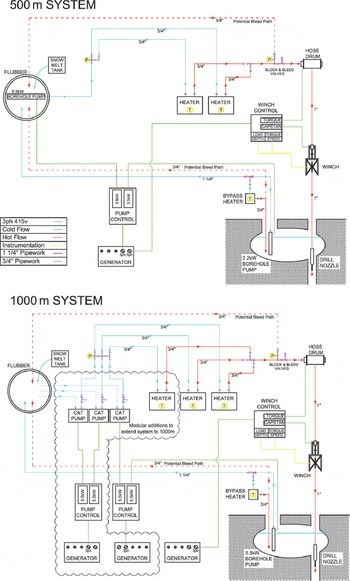
Fig. 2. The hot-water drill system for (a) up to 500 m ice depth and (b) up to 1000 m ice depth. The additional equipment required for the upgrade to 1000 m is inside the scalloped and dotted outline, and the 5.5 kW borehole pump is reused in the cavity.
To reduce the number of diesel or petrol engines within the system and eliminate hydraulic systems, three-phase generators and electrical motors with variable-frequency drives (VFDs), that control voltage and frequency and therefore speed and torque, were selected for all pumps and winches, increasing system flexibility and power efficiency. VFDs allow the ramping-up of power during motor start-up until the operating speed is reached. This eliminates the required three to six times over power requirement for direct motor starts and oversizing of generators. Furthermore, as most motors can run at 60 Hz, motor speeds can be increased by 20% if required, or, in low-load situations, significant power and therefore fuel saving can be made. By using petrol engines rather than diesel engines for comparable generators, weight is typically decreased by a factor of 2, which is highly beneficial for aircraft-loading operations while petrol is also available at field camps. The primary electrical generators are 15 kVA, three-phase, super-silenced units, from which various combinations of motors can be powered (e.g. 2 × 5 5 kW, 1 × 9.2 kW, or multiple smaller motors). Three-phase power enables smaller, lighter motors and power cables to be used, particularly for the long cable down to the return water submersible borehole pump.
The greatest electrical power requirement in hot-water drill systems comes from high-pressure pumping, which is necessary to overcome the frictional losses in surface pipe work and hoses, and deliver the required flow of hot water to the drill nozzle spray The pressure loss (Pa) can be calculated using forms of the Darcy-Weisbach equation
where the dimensionless friction coefficient (f d) is <0.02 for hoses and 0.03 for heat exchanger coils, L and D are the hose length (m) and internal diameter (m), v and Q are the mean flow velocity (m s−1) and volumetric flow rate (m3 s−1), and ρ is water density (kg m−3).
The operational pressures of the two drill configurations are significantly different as the pressure required increases linearly with hose length and with flow rate squared. Pressure losses in the surface equipment are minimized by adding heaters in parallel to reduce the flow velocity, and by using oversized manifolds, valves and hoses with a 32 mm (1¼ in) bore. In the 1000 m system configuration with an additional heater, a higher flow rate of ∼33% and doubling of the drill hose length results in a system pressure around three times greater than for the 500 m drill system. At the drill nozzle, the pressure loss is offset by the 600–1000 kPa pressure gained from the 60–100 m head between the surface and water level in the hole.
With relatively low operating pressure in the 500 m system and the desire to have a simple and reliable drilling system, a submersible borehole pump provides the primary pumping capacity. These simple rotary multistage centrifugal pumps develop sufficient pressure to deliver the required flow rate, and have the added advantage of not requiring pressure-relief valves to protect the drilling system from damage. A single pump with a 5.5 kW (0.8 PF) motor provides 90 L min−1 at 2100 kPa for the 500 m system, but the maximum pumping efficiency is only 66%. For the higher-capacity, higher-pressure 1000 m system, centrifugal pumps become less practical and three positive displacement pumps with 5.5 kW motors (0.87 PF) offer a more efficient (85–90%) pumping solution. Three pumps can deliver 120 Lmin−1 at 6900 kPa, and two pump units can be powered by a single generator, while the 5.5 kW centrifugal pump is redeployed to recover water from the deeper borehole cavity.
Further power is also required for the submersible borehole pump used to recover the cold return drill water to the surface and complete the water recirculation system. As ice-shelf thickness, H (m), increases, the downhole depth to the water level, h (m), also increases. Following Vaughan and others (Reference Vaughan1995), this depth can be estimated using
where ρ sw is the sea-water density (1027 kg m−3) and ρ hw the hole water mean density which is typically fresh meltwater (1000 kg m−3), provided no significant volumes of sea water are drawn into the hole, increasing the mean density. On ice shelves where summer surface melt occurs, surface snow densities increase, and h can be reduced by several meters, to a maximum of ∼17 m. The submersible borehole pump must be positioned below this water-level depth to guarantee the return drill water supply once ocean access is achieved. For the 500 m system, a single borehole pump with a 2.2 kW motor is capable of maintaining the 90 L min−1 return drill water supply from below at least 60 m, while the 1000 m system uses the 5.5 kW borehole pump from the 500 m system to maintain the increased return flow of 120 L min−1 from below at least 102 m.
Drill Equipment Summary
Water storage tank
Flexible coated fabric tank with 10 000 L capacity with at least 5 cm of closed cell ethafoam insulation to prevent melting into snow surface.
Generator
Europower super-silenced EPS15000TE three-phase generator. Maximum output of 15 kVA and 12.5 kVA continuous, delivering 50 Hz three-phase (400 V) and single-phase (230 V) power, housed in an acoustic canopy. The engine is a two-cylinder Honda GX690 that consumes up to 7 L h−1 of petrol at full power.
Main 500 m drill pump
Caprari E6X25-4/24 multistage centrifugal submersible pump with a 5.5 kW (0.8 PF) motor, capable of delivering 90 L min−1 at 2100 kPa.
Return 500 m drill water pump
Caprari E4XP35/20 multistage centrifugal submersible pump with a 2.2 kW (0.8 PF) motor, capable of delivering 90 L min−1 at 980 kPa. The pump is connected to an umbilical consisting of a H07RN-F three-phase power cable, 1¼ in thermoplastic return hose, and a ¾ in thermoplastic hose to deliver hot water to the pump and cavity. A water-level sensor and cable is also attached to the umbilical.
Main burners and heat exchangers for 500 m drill
Two Exchange Engineering heat exchangers, each with an output of up to 250 kW, consisting of ∼100 m of ¾ in bore stainless-steel tube wound into a double coil rated to 6900 kPa. The oil burners are Nu-Way MOL 350 units, operating on 230 V and at a fuel pressure of 860 kPa, each consuming 0.75 Lmin −1 of Jet-A1. Each unit is fitted with adjustable high-temperature and low-flow cut-off switches.
Secondary burner and heat exchanger
Jet-A1 burning unit with a 60 kW output to provide heat to borehole cavity and pump or water storage tank.
Drill hose
A single 500 m length of Kutting thermoplastic hose (nominal 1 in bore) consisting of a polyester elastomer lining, a polyester braid and a polyurethane outer jacket. The maximum working pressure is 6900 kPa with a 4 : 1 safety factor of dynamic applications, with operating temperatures o f −40 to 100°C, and a weight of 0.52 kg m−1 in air. The hose is slightly negatively buoyant in water, which acts to counter the 0.02 kg m−1 buoyancy of the hot water in the hose.
Drilling winch
The hose drum, which is assembled on site, holds 1000 m of 1 in bore drill hose and is driven by a 0.37 kW torque motor via a 1 : 72 gearbox that provides constant tension to the hose between the winch drum and capstan. The capstan, with a 2.5 m circumference, powers the drill hose up and down the hole and is driven by a 1.1 kW motor coupled to a 1 : 137 self-locking worm gearbox. The winch speed range of 0–9 m min−1 can be controlled in increments of <0.05 m min−1. The winch tower has an instrumented sheave wheel that gives a clearance of 3 m above the hole and can be used independently of the capstan for the deployment of coring and sampling equipment, oceanographic instruments and moorings using either 1.5 kW electrically powered instrument winches or a snowmobile.
Basic drill monitoring
Sensors and display units output drill water temperature, pressure and flow, as well as the hose load, drilling speed, drill depth and borehole water level above the submersible pump.
Total weight
The basic 500 m drill system weighs ∼3200 kg, and including comprehensive spares, windbreaks and 6 ft × 10 ft (1.8 m × 3 m) Weatherhaven tent, this increases the total to ∼4600 kg. For planning purposes, drilling a 30 cm hole at a new site, and then reaming after 12 hours, requires roughly an initial 230 L of Jet-A1 and then 230 L per 100 m of ice depth. The petrol to Jet-A1 ratio is 1 : 10. Therefore a 500 m hole requires ∼1440 L of Jet-A1 and 150 L of petrol or just under 1500 kg if provided as 205 L drummed fuel.
Although much of the 500 m drilling system remains unchanged in upgrading to the 1000 m system, additional modules are needed for the increases in depth, thermal power and electrical power required for the drill system and include: 500 m of 1 in bore drill hose, 60 m of borehole pump umbilical, a main burner and heat exchanger, and two 15 kVA generators (Fig. 2b). These additions, including the three CAT pump units, add ∼1800 kg, for the upgrade to the 1000 m drill system. With additional electrical power requirements the petrol to Jet-A1 ratio changes to ∼1 : 6. The Jet-A1 requirement is estimated as an initial 500 L and then ∼250 L per 100 m of ice depth. For a 1000 m hole, 30 cm in diameter, the total fuel requirement is ∼3250 kg if provided as drummed fuel.
Main 1000 m drill pumps
Three positive displacement CAT1531 plunger pumps, each with a 5.5 kW (0.87 PF) motor and capable of delivering ∼40 L min−1 at 6900 kPa. Pulsation dampers and pressure relief valves are fitted to each unit.
Return 1000 m drill water pump
Redeployed main 500 m system 5.5 kW centrifugal submersible drill pump capable of delivering 120 L min−1 at 1700 kPa.
Drill Tools
The main body of the nozzle assembly is a 50 kg brass pipe, 1.5 m long and 75 mm in diameter, that provides weight to maintain the verticality of the hole. At the front, a variety of drilling tools and sprays can be attached, while a hole reamer can be added at the back of the nozzle.
Drill nozzle sprays
Various spray configurations are required during different phases of drilling an access hole to the ocean. Typically 15° FullJet® full cone sprays are used initially to drill the required hole diameter down to the depth of the cavity through the porous firn and, in some areas, through thick ice lenses formed by refreezing summer melt and prevalent throughout the firn. To accelerate the lateral formation of the cavity, a 150° DeflectoJet® and/or a ring of horizontal VeeJet® sprays can be used. Once in non-porous ice, a forward point 0° jet is used to give good forward penetration (Fig. 3a). Typically the pressure drop across the nozzle would be in the range 500–1000 kPa to give an exit velocity of 30–40 m s−1 which is essential for rapid hole formation in advance of the drill nozzle, thus maintaining both acceptable drilling speed and hole verticality, and making the hole diameter large enough to allow the nozzle to pass through with further melting taking place over several meters above the nozzle. At 90 L min−1 the back thrust can be up to 60 N and a heavy nozzle assembly is essential to counteract this force and maintain a vertical hole. Operating in low ice temperatures with a single forward-pointing water spray, a potential problem exists. In drill hoses where a loss of pumping pressure results in hose elongation, a system failure that also includes loss of winching power can quickly result in a spray tip frozen to the hole bottom and blocked with ice. With no heat flow to the nozzle, no melting can take place, resulting in the nozzle, hose and hole being lost. By adding up to six small forward-pointing water jets a short distance above the main spray tip (Fig. 3a), this problem is avoided and, once flow is re-established, melting-out of the tip will occur and full drilling can be re-established.

Fig. 3. Drill nozzle attachments: (a) point spray with small secondary sprays marked in red, and (b) the nozzle cups attachment for sediment recovery.
Sediment cups
Antarctic ice shelves are generally devoid of rock material, and any glacial rock debris near the ice base would be expected to melt out very soon after the ice goes afloat in the ice shelf. However, at a northwest Ronne Ice Shelf drill site, a substantial amount of englacial debris 60 m above the ice-shelf base and associated with a thick marine ice layer was encountered (Reference Nicholls, Corr, Makinson and PudseyNicholls and others, 2012b), making drilling difficult. To allow future sampling or removal of such material from drillholes, several sampling cups can now be added in series to the drill nozzle (Fig. 3b) so that in the highly turbulent environment of the nozzle tip, sediments are lifted into these simple sediment traps. These sample cups give an integrated measure of debris content within part of the ice shelf, whereas hot-water ice coring allows examination of the debris within the ice at a known depth from which the core was collected (e.g. Reference Roberts, Craven, Cai, Allison and NashRoberts and others, 2007). Also, when drilling on grounded ice, these cups can collect an initial basal sediment sample prior to the deployment of a purpose-built sampler, such as a sediment corer.
Reamer
Once drilling of the access hole through the ice shelf is complete, it is often necessary to guarantee a minimum hole diameter, particularly before the deployment of larger instruments. By adding a reamer of sufficient diameter to the top of the drill nozzle, its passage through the hole ensures a minimum hole size. During the reaming process no forward-pointing sprays are used, removing the possibility of accidentally drilling into the hole side-wall and creating a secondary hole (Reference MakinsonMakinson, 1993), therefore only lateral or backwards-pointing sprays are used and the nozzle guides the reamer down the existing hole. Figure 4 shows the bidirectional reamer attachment and a section through it, and one example spray configuration when it is activated. The spring-loaded reamer valve, similar to the system described by Reference Engelhardt, Kamb and BolseyEngelhardt and others (2000), is activated when contact is made with a narrowing in the hole when travelling either down or up the hole. Both springs are adjustable over a wide range of activation loads and are set prior to deployment. Typically, a force of ∼200 N is sufficient to fully activate the valves, with the drill monitoring system signaling the changes in hose load and water pressure when this activation occurs. Also, when recovering the drill, a limit can be set on the capstan motor controller to prevent an overload and damage to the hose. The reamer is made up of a series of aluminum plates containing holes and channels that can be stacked together to provide a range of diameters from 150 to 350 mm in steps of 50 mm. When activated, hot water flows through the network of holes and channels within the reamer. Water sprays laterally at locations in the stack where spacers are placed, such as at the largest diameter of the reamer (Fig. 4). Using a longer ream shaft, the space between the reamer cones can accommodate a small temperature data logger (not shown) that is used to measure the temperature of the drill water reaching the nozzle. The downhole data, together with temperature and flow data from the surface, are then used to confirm the effective thermal conductivity of the drill hose, which is an important parameter when used in conjunction with drilling speed, in predicting the size of the hole created during drilling (Reference Humphrey and EchelmeyerHumphrey and Echelmeyer, 1990).

Fig. 4. Illustration of the reamer outer surface on the left and in cross section on the right. The red arrows indicate where water can spray from the reamer and the valve is show in the off position.
Drill brush
The through-ice-shelf deployment of a Rockland VMP turbulence probe required enlargement of the lower 5–10 m of the ice shelf to a diameter of ∼1 m to allow the unimpeded free fall of the instrument through the ocean boundary layer at the ice-shelf base.
However, a common problem encountered when drilling through ice shelves is that the hole narrows significantly at the ice-shelf base (Reference MakinsonMakinson, 1993). This narrowing results as the drill reaches the ice base and access is first gained to the ocean. Depending on whether the water level in the hole is maintained above or below the calculated water level, warm water rushes out into the sea or cold sea water enters the hole as the water level adjusts to sea level. In either case, the heat necessary for enlarging the hole near the ice base is lost and much of the hot water from the drill nozzle is lost to the ocean, resulting in a reduced diameter over several meters near the ice-shelf base. In areas with permeable marine ice similar problems arise, resulting in irregular, narrow and highly asymmetrical exit holes at the ice-shelf base (e.g. Reference Nicholls, Makinson and RobinsonNicholls and others, 1991; Reference Craven, Allison, Fricker and WarnerCraven and others, 2009). Repeated passes over this lower section of hole and reducing the return pumping rate to minimize cold sea-water inflow will ensure melting continues as warm water fills the lowest part of the hole, rectifying much of this problem. However, over the final few centimeters of ice-shelf base, or within permeable marine ice, it can be particularly difficult to enlarge the hole as heat is still lost to the ocean.
The requirement of a 1 m diameter hole at the ice-shelf base therefore necessitated a new type of drill nozzle design to isolate the hot (>60°C) drill water required to enlarge the hole from the cold (−2°C) sea water below. This was achieved using a flexible brush and eight horizontal fan sprays, which can traverse a 30 cm borehole and unfold to its full 1 m diameter once beneath the ice base (Fig. 5). During the 2011/12 Antarctic field season this brush was successfully used beneath the Larsen C and George VI ice shelves. Monitoring the relative hose load, it was clear when the brush was traversing the hole (−5 to −8 kg) (Fig. 5a), passing through the ice-base narrowing (−12 kg), had fully entered the ocean (0 kg) and was pulled up against the ice base (+3 kg) (Fig. 5b) and then recovered back up the 30 cm hole (+6 kg) (Fig. 5c). The brush was initially held at the ice base for up to 20 min to ensure a wide opening at the base, and then, to widen the hole diameter to 1 m, it was recovered at 0.3 m min−1 over the lower 10 m. Similarly, in permeable marine ice areas it is highly likely that this brush attachment will remove the problems of hole irregularity and narrowings at consolidated ice layers. Using this brush to separate the drill water from the underlying sea water, less salt water enters the hole, which is beneficial for precise ice-shelf temperature measurements using thermistor cables frozen into the borehole. Tests also showed that the brush was able to reverse direction within the 30 cm diameter hole.
Fig. 5. Drill brush at the ice-shelf base (a) going down the hole with no hot water flow, (b) at the ice base and drilling upwards slowly and (c) at the ice base and drilling quickly before recovery up hole.
A potentially serious problem associated with the ice-shelf base is the entrapment of cables and loss of profiling instrumentation even when cone attachments have been added to the top of instruments to aid their transition into the hole. Once lowered into the ocean, instruments and up to hundreds of meters of cable can be swept off vertical by ocean currents, causing the wire to cut into the borehole wall at the ice-shelf base and form a keyhole (Fig. 6a). Repeated profiling exacerbates the problem, and recovery of the instrument into the hole can be difficult or even impossible, resulting in the loss of the instrument and cable which must be cut at the surface. This is particularly acute with small-diameter steel cables rather than with large cables with smooth outer jackets (e.g. polyurethane). By using the drill brush at the ice-shelf base to make an enlarged conical hole (Fig. 5b and c), instruments can easily transition back into the hole.

Fig. 6. Illustration of the recovery rod in operation. (a) The oceanographic instrument wire-cutting slot into the hole wall during profiling, (b) the recovery rod pushing the cable out of keyhole slot, and (c) the instrument ready for recovery into hole.
Instrumentation Tools
In addition to the various drill nozzle attachments, two further tools to ensure successful working through ice shelves have been developed.
Recovery rod
Where it is not practical to ream the hole at the ice base using the brush reamer because of large ice depths and long transit times for the drill for example, the risk of not recovering profiling instruments remains high. Instrument recovery using the HWD, even with the drill nozzle guided along the cable, risks losing all the downhole equipment and blocking the access hole itself, particularly with plastic-coated cables that stick to the hose or if the hose becomes wrapped around the cable. Once an instrument becomes trapped at the ice base it can be recovered into the hole using a recovery rod. The recovery rod is a metal tube ∼2 m long, 4.3 cm in diameter, weighing 7 kg with a slot along its length. The rod is placed over the cable and held in position by stainless-steel hemispheric end caps that centralize it on the cable and prevent it becoming embedded in the hole wall. With the trapped instrument pulled up against the ice base, the rod slides down the cable, slowing rapidly as it pulls the cable from the keyhole slot in the hole wall at the ice-shelf base (Fig. 6b), and freeing the instrument for its recovery up the hole (Fig. 6c). On the George VI Ice Shelf, an oceanographic profiling instrument twice became trapped at the ice-shelf base; on both occasions the recovery rod was deployed and the instrument was successfully recovered undamaged.
Ice-shelf base catch
The centimeter level of positioning with respect to the ice base of long-term sub-ice-shelf instrumentation moorings is important, especially for boundary layer experiments with a high density of sensors at or near the ice/ocean interface (Fig. 1b). During mooring deployment, the folded ice-base catch is attached to the mooring cable and lowered down the hole. Once past the ice base, the arms deploy, and the mooring is then slowly raised using a hand winch. The cable tension is monitored on the winch tower, with an increase in cable tension indicating the catch has engaged with the ice-shelf base and the mooring is in the correct position (Fig. 7). In marine ice areas where the ice-shelf base is not consolidated, a catch with longer, wider and even multiple arms would provide the best prospect for correct positioning at the ice base. If problems are encountered with the mooring soon after deployment and before the cable becomes frozen into the hole, the catch has breakable pins supporting each arm, allowing them to fold down for mooring recovery. Recovery part-way through a deployment cannot be guaranteed, as irregularities in hole diameter may result in the arms partially opening and catching on the hole walls. However, some upward motion of several meters is generally possible.
Fig. 7. Ice-base catch mounted on the mooring cable, fully open and engaged against the ice-shelf base.
Drilling Method
The method of drilling has remained largely unchanged from Reference MakinsonMakinson (1993), with only a brief summary given below, while the new ice-shelf drill itself is significantly enhanced in terms of its capability, simplicity and reliability. During the 2011/12 Antarctic field season, the 500 m system penetrated almost 400 m ice on five occasions with a minimum temperature of −12°C. The system delivered 90 L min−1 at 80°C, an output close to 500 kW and capable of melting −12°C ice at a rate of 84 kg min−1, or 1 m3 in ∼11 min.
Initially the drill was assembled and the 10 000 L flubber was filled during the first day. During the second day, the first hole was drilled to 60 m at <1 m min−1, paused for 5 min and then the drill recovered. The submersible borehole pump was deployed to recover water, effectively completing the basic drill system tests. The drill tower was moved laterally by 0.5 m and drilling of the main access hole to 60 m commenced. Helped by the use of lateral fan sprays, the two holes were interconnected, establishing the water recirculation system cavity. Drilling to the ice-shelf base could then continue. However, to minimize the period of continuous drilling, sampling and deployment operations, drilling ceased and the holes and cavity were pumped dry and the pump recovered.
On days three and four, the borehole pump was redeployed and drilling proceeded from 60 m depth at ∼0.9 m min−1 until a rapid change in water level within the hole indicated the ocean had been accessed. The drill was paused for a few minutes to enlarge the hole at the base of the ice shelf. The lowest 3 m of the hole was then traversed at 0.4–0.6 m min−1 to further enlarge the hole at the ice base. The drill was then recovered at 9 m min−1. If required, additional reaming at the ice base using nozzle brush attachment could also be undertaken. With refreezing reducing the hole diameter by up to 4 mm h−1 (Reference Cooper, Nicholls, Morris and TalbotCooper and others, 1988), the access hole was used for ∼12–16 hours by various oceanographic instruments, samplers and corers, before reaming the hole. If required, this cycle of instrument deployment and reaming can be continued over several days to allow a number of experiments to be run and/or repeated. Once this phase was completed, the final ream confirmed the hole was sufficiently large before deploying the permanent sub-ice-shelf instrument mooring. From restarting to drill the main 400 m hole through to having the mooring installed below the ice shelf typically took 24–30 hours. During day five, the drill system was then decommissioned and packed ready for Twin Otter aircraft uplift.
Future Developments
The recent introduction of new over-snow tractor traverse capabilities into the BAS Antarctic logistic infrastructure provides an opportunity to change the way in which BAS hot-water drills are delivered to and transported between drill sites, particularly on large ice shelves. During the forthcoming 2014/15 field season, the 1000 m hot-water drill system will be assembled and mounted on several 7 ft × 7 ft (2.1 m × 2.1 m) steel pallets and attached to a 72 ft × 8 ft (22 m × 2.5 m) tractor-towed plastic sled. An additional small 1350 L well-insulated bladder will hold warm seed water to prime the drill system, making it possible to start snowmelting to refill the flubber soon after arriving at new drill sites during the season. Once the initial drill system set-up is completed, the usual 2 or 3 days for setup, tear-down and initial snowmelting for seed water will be saved at each site. Also, the non-reliance on much more weather-dependent aircraft support will save several days during each site move. The net result of these logistical changes for multi-site and multi-season drilling is a highly efficient program of hot-water drilling operations on the Filchner-Ronne Ice Shelf.
Acknowledgements
This study is part of the British Antarctic Survey Polar Science for Planet Earth Program. It was funded by the UK Natural Environment Research Council. We also thank Mike Craven, Alan Elcheikh and Lee Greenler for constructive review comments which appreciably improved the manuscript.


