


Introduction
The growth in new wireless services and the emergence of novel technology uses will propel the development of advanced wireless communication systems that can effectively and efficiently handle various tasks. The wireless body area network (WBAN) has recently garnered significant attention in academic research for its potential to revolutionize wireless communication technologies. The health-care industry, military and emergency rescue operations, sports, and other sectors are expected to be significant adopters of WBAN due to its low-cost and high-quality wireless network services. The communication links in WBAN rely on multiband antennas to perform various functions [Reference Bhattacharjee, Maity, Chaudhuri and Mitra1]. Hence, multiband, low-profile, high-gain antennas will be essential for WBAN and the upcoming 6G networks. The design of microstrip antennas has shifted toward structural simplification, which is becoming a key trend while still maintaining the desired features of multiband capability, impedance bandwidth, realized gain, and outstanding performance. The mortality rates related to COVID-19 continue to increase worldwide, particularly among the elderly and individuals with pre-existing medical conditions. Health-care professionals must exercise additional caution while treating patients with COVID-19 due to the contagious nature of the virus, making it imperative to adopt a non-invasive approach. WBAN communication, specifically wearable technology, has emerged as a promising solution. Researchers are currently focusing on the antennas utilized in WBAN communication, as they play a crucial role in its success. Microstrip patch antennas, with their versatility and efficiency, have been a popular choice for wireless communication systems for the past three decades. Their use in the medical field has recently seen tremendous growth due to their numerous advantages.
Wearable electronics require compact, flexible antennas and offer high gain while ensuring low specific absorption rate (SAR) levels. In addition, a WBAN allows data transmission between nearby wearables (known as “on-body communication”) or to wearables that are more distant (referred to as “off-body communication”). Antennas embedded in or wrapped around the user enable these communications. When designing WBAN antennas, factors such as SAR and polarization mismatch must be considered, making the design process distinct from conventional antennas. Antennas used in WBAN applications, particularly for off-body communication, must be able to transmit signals across several frequency bands in specific directions. A single antenna configuration may be necessary to meet the demands of multiband communication. Methods for creating multiband antennas include radiation patch slots and fractal technology [Reference Wei, Li, Wang, Xu and Xing2]. The radiation performance of these antennas can be improved through artificial magnetic conductor (AMC), which has in-phase reflections and can be considered as a super material. AMC produces a plane-wave reflection with the same electromagnetic characteristics as the incident wave, leading to a low-profile design with a unidirectional radiation pattern, superior performance, and low back radiation.
A wide range of advanced techniques and models have been proposed recently for designing antennas and AMCs [Reference Contopanagos3–Reference Abbas, Singh, Sharma and Gangwar7]. Different shaped and sized antennas, such as wearable antennas [Reference Chen, Liu, Fan and Yang8], planer inverted-F antennas [Reference Lin, Saito, Takahashi and Ito9], microstrip antennas [Reference Del-Rio-Ruiz, Lopez-Garde, Legarda, Caytan and Rogier10, Reference Benkhadda, Saih, Chaji, Ahmad and Reha11], monopole antennas [Reference Verma, Arya and Raghava12], and AMC-supported multiple-input multiple-output (MIMO) antennas [Reference Malekpoor, Abolmasoumi and Hamidkhani13], have been suggested for WBAN communications. However, these antennas are limited to a single frequency range, making multilink transmission impossible. In paper [Reference Paracha, Rahim, Soh, Kamarudin, Tan, Lo and Islam14], an AMC reflector-backed dual-band, dual-polarized antenna of 70.4 × 76.1 × 43.11 mm3 size was designed for Wireless Local Area Network (WLAN) usage. It showed a zero-degree reflection coefficient at two resonance frequencies with strong gain enhancement performance. Yang et al. [Reference Yang, Ji, Ge, Zeng, Wu and Liu15] proposed a dual-band patch antenna with separate radiating elements to achieve different radiation properties, with a maximum gain of 3.1 dBi at the lower frequency. The antennas in papers [Reference Jagtap, Chaudhari, Chaskar, Kharche and Gupta16] and [Reference Gao, Yang, Hu, Zhang and Wang17] have gains more significant than 10 dB, but their complex structures and large size hinder their application. Thus, the challenge remains to develop a compact, wideband microstrip antenna with high gain, high efficiency, low cost, and lightweight. Yang et al. [Reference Yang, Liu, Fan and Xiong18] presented a dual-band antenna that is flexible and capable of dual circular polarization, high gain, and low backward radiation, making it suitable for long-range connections. Antenna operating in the 5.8 GHz Industrial, Scientific, and Medical (ISM) and 3.5 GHz Worldwide Interoperability for Microwave Access (WiMAX) bands are designed for wearable devices. Annavarapu et al. [Reference Annavarapu, Ghosh, Singh, Chattopadhyay and Sim19] developed a planar antenna based on dielectric AMC for Internet of Things applications in the P band, with a small patch size of 0.16λ0 × 0.20λ0 × 0.01 λ0 and a gain of 3.1 dBi. Gupta et al. [Reference Gupta, Patil, Dalela and Kanaujia20] showed a fractal H-shaped antenna with a flawed ground structure, with circular polarization that makes it suitable for use with Bluetooth, LTE, GNSS, S-, and C-band devices.
The previous studies in the field mainly concentrated on improving the performance of single- or dual-band antennas by incorporating AMCs with limited frequency coverage. A triband microstrip antenna with a tricyclic stacked structure was proposed in paper [Reference Yu, Yang, Chen and Zeng21], featuring good gain across three frequency ranges and an elliptic-shaped defected ground structure to enhance bandwidth and radiation efficiency. Another research [Reference Gao and Zhao22] explored a patch antenna that met the criteria of being triband, had improved bandwidth, high gain, and a diverse radiation pattern, with a gain of 6.35 dBi at 1.79–1.81 GHz, 6.1 5dBi at 3.74–4.0 GHz, and 9.42 dBi at 4.93–5.44 GHz. However, designing triband AMC-backed antennas is challenging since it requires a complex design of an AMC with three or more zero-degree phases in its reflection coefficient, and few triband AMC-based antennas have been reported so far. Despite these challenges, researchers have been making significant efforts to develop AMC-supported multiband antennas.
The use of AMCs in microstrip antennas has been well documented in the literature to enhance the radiation performance of the antenna. In paper [Reference Jiang, Wang, Nie, Zhao and Huang23], a slotted dipole antenna with a compact profile and a broad operating frequency range is presented, utilizing an AMC structure of 6 × 6 unit cells. This design achieved gains of up to 9.9 dB in the C band. In paper [Reference Zhou, Sun, Yang, Li and Wong24], a blueprint is developed for a bilayer AMC, where the dipole and patch hybrid modes are activated using a single feeding and standard aperture, resulting in an impressive 51.3% impedance bandwidth across the frequency range of 1.68–2.8 GHz. The ultra-wideband meta surface reported in paper [Reference Lin, Huang, Guo, Wang, Ye and Ji25] can switch from linear to circular polarization with over 93% efficiency, covering a frequency span from 7.08 to 25.86 GHz. Reflector elements have been proposed for construction on a reconfigurable AMC platform, with a return loss of −15 dB and 12 different radiation patterns, as described in paper [Reference Singh, Khalily and Tafazolli26]. El Atrash et al. [Reference El Atrash, Abdalla and Elhennawy27] explain the CRLH (composite right/left-handed) approach to the π-section and the strategic installation of a 2 × 2 AMC array for better performance in WBAN and medical settings. Saeed et al. [Reference Saeed, Balanis, Birtcher, Durgun and Shaman28] report a new flexible and reconfigurable antenna for mobile remote patient monitoring systems, emitting orthogonally polarized waves in the WBAN and WiMAX spectrum and a polarization-dependent dual-band AMC surface to enhance radiation performance and reduce SAR. In paper [Reference Gong, Yang, Li, Chen, Tong and Yu29], a quad-band coplanar waveguide antenna equipped with an AMC, including four zero-phases of the reflection coefficient, is used to achieve multiband and high-gain features. The present paper aims at to design a novel multiband AMC-based antenna by overcoming the aforementioned limitations.
This paper outlines a novel design for a low-profile, high-gain, low-SAR multiband AMC patch antenna for off-body communication systems. The design incorporates a polygonal radiating patch with different segment counts and an AMC surface of 4 × 4 unit cells placed at a distance of 0.104λ0 from the bottom of the antenna. The polygonal patch is constructed with three patches of varying segment counts that are rotated concerning each other to provide multiband responses. The AMC unit cell generates four zero-degree reflection phase responses with double negative (DNG) behavior at 2.5, 3.8, 5.5, and 7.5 GHz. The proposed patch antenna and AMC surface combination generate five distinct resonance points at 2.4, 3.2, 5.5, 7.5, and 10 GHz. The antenna reaches its highest gain at 6.01 GHz, reaching 8.55 dBi, and boasts an impressive 31.5 dB front-to-back ratio (FBR) at 4.5 GHz. The proposed antenna has dimensions of 0.23λ0 × 0.296λ0 × 0.0128λ0, not including the AMC surface. Human phantom simulations have shown the combined design to have a SAR of 0.0627 W/kg at 2.4 GHz. The proposed antenna and AMC surface were tested and verified in a vector network analyzer (VNA) and an anechoic chamber.
Design and characterization of a quad-band AMC unit cell
Design and geometry of AMC unit cell
There has been significant research on thin-layer AMC structures that act as perfect magnetic conductors at the resonance frequency [Reference Sievenpiper, Zhang, Broas, Alexopolous and Yablonovitch30]. The 4 × 4 AMC surface is constructed by arranging periodic unit cells with a gap of 0.1 mm (G g). The unit cell comprises a dielectric substrate and a metallic ground. The normal incidence illumination of a plane wave is used as the standard benchmark for evaluating the properties of an ideal AMC. The operating bandwidth of an AMC structure is defined by the phase range [+90°, −90°], and the resonance frequency corresponds to phase 0° of the reflection coefficient. A zero-degree reflection coefficient for the AMC plane in the operating frequency range signifies that it will produce in-phase reflection concerning the incident wave. However, designing a simple structure that can reflect various zero-phase AMC frequencies in the required spectrum is challenging. The AMC is designed to provide four zero-phase reflections to enhance the radiation performance of the proposed multiband antenna.
The proposed AMC unit cell design, as depicted in Fig. 1(a), consists of a square patch and three polygonal patches with varying numbers of segments. The unit cell has a compact size of 16 × 16 × 1.6 mm3 and is constructed using the FR4 material, which has a relative permittivity of 4.4 and a loss tangent of 0.02. The simulation of the unit cell was performed using ANSYS HFSS with the incorporation of the floquet port and master-slave boundary conditions. In Fig. 1(b), the reflection phase and magnitude response of the proposed AMC unit cell is illustrated, with zero-phase reflection observed at frequencies of 2.5, 3.8, 5.5, and 7.5 GHz. The width of the nonagon, octagon, and heptagon metal strips is represented as W 2, W 3, and W 4, respectively. A summary of the unit cell’s optimal parameters is provided in Table 1.

Figure 1. The design and response of the proposed unit cell (a) geometry and (b) reflection phase and magnitude.
Table 1. Summary of optimized AMC unit cell parameters

Development of the AMC unit cell
The evolution of the AMC unit cell involved five stages of development. Three fundamental components make up the final unit cell design. These are a square-shaped patch, a polygonal patch composed of three metal segments, and an arrangement of eight rectangular patches. The entire design process is illustrated in Fig. 2, with each stage designated as AMC-I through AMC-V. The initial stage, shown in Fig. 2(a), features a conventional square patch that accommodates the wireless frequency spectrum and exhibits zero-degree reflection at 2.5 GHz. The subsequent stages, from AMC-II to AMC-IV, involve polygonal metallic patches created by drawing a circle and labeling its circumference with the desired number of segments using ANSYS HFSS. In the second stage, AMC-II, a nonagon-shaped patch was implemented, consisting of an outer and an inner nonagon with radii R 6 and R 5, and side lengths L 6 and L 5, respectively. The inner nonagon was rotated relative to the outer nonagon so that its corners would fall precisely in the middle of the sides of the outer nonagon. The reflection phase response of AMC-II, which exhibits a second zero-degree reflection at 3.85 GHz, is depicted in Fig. 2(b). Figure 3 presents the reflection phase response.

Figure 2. The evolution of the AMC unit cell: (a) AMC-I, (b) AMC-II, (c) AMC-III, (d) AMC-IV, and (e) AMC-V.

Figure 3. The reflection phase response of the AMC unit cell at various evolutionary stages.
The development of the AMC-III and AMC-IV followed the success of Step 2. Figure 2(c) and (d) shows the AMC-III and AMC-IV, respectively, created with an octagon and heptagon shape. In Step 4, the proposed unit cell had four frequencies (2.52, 3.84, 5.48, and 7.44 GHz) identified with a zero-degree reflection phase. Although a quad-band AMC was produced, the bandwidth and material properties were not optimal, and the third- and fourth-band responses needed to be improved. Therefore, the AMC-V design in Fig. 2(e) was created by adding eight additional rectangular patches of size R x × R y to AMC-IV in Step 5. With these modifications, AMC-V showcased the desired DNG characteristics and zero-degree reflection phase at 2.5, 3.8, 5.5, and 7.5 GHz. Table 2 summarizes the bandwidth results of the AMC unit cell at each step in its evolution process.
Table 2. Bandwidth comparison of AMC unit cell development stages

Exploring the impact of unit cell parameters on AMC design
The resonant frequency of the AMC unit cell has been optimized by exploring two critical parameters in five different stages. First, the reflection phase of the incident wave that strikes the surface is described by equations (1) and (2) [Reference Dewan, Rahim, Hamid, Yusoff, Samsuri, Murad and Kamardin31]. The reflection phases of the simulated quad-band AMC are depicted in Fig. 4, which varies according to the values of W 2 and W 3. The parameter W 2 significantly influences the fourth frequency band, causing the resonant point for the fourth band to move to a higher frequency as W 2 increases.

Figure 4. Parametric analysis of the unit cell: The effect of variations in (a) W 2 and (b) W 3.
On the other hand, W 3 affects both the third and fourth frequency bands. As a result, the AMC exhibits triband behavior only when W 2 = 0.35 mm and W 3 = 0.3 mm. The optimal parameters of the unit cell, calculated by applying equations (1) and (2) to the reflection phases of the AMC unit cell, are presented in Table 1.
 \begin{equation}\varphi = {\textrm{Im}}\left\{ {\ln {{\left( {{Z_{{\textrm{S_AMC}}}} - \eta } \right)} \over {\left( {{Z_{{\textrm{S_AMC}}}} + \eta } \right)}}} \right\}\end{equation}
 \begin{equation}{Z_{{\textrm{S_AMC}}}} = {{j\omega {\textrm{L}}} \over {1 - {\omega ^2}LC}}\end{equation}
AMC unit cell with different incidence angles
The dependence of the surface impedance (Z s_AMC) of the AMC unit cell on the incidence angle of plane waves can be attributed to its behavior as a high impedance surface [Reference Simovski, de Maagt, Tretyakov, Paquay and Sochava32]. The behavior of the impedance for both transverse electric (TE) and transverse magnetic (TM) polarized waves varies based on the angle of incidence. The stability of the AMC structure against changes in the incidence angle has been studied by evaluating the phase–frequency relationship of the reflection coefficient for incident angles (θ) ranging from 0° to 180° for both TE and TM polarized waves as shown in Fig. 5. TE- and TM-polarized waves have incidence angles from 0° to 180°. Despite the change in incidence angle, the first two operational bands remain unchanged for both types of polarized waves. However, the third and fourth resonant frequencies of TE polarized waves decrease to 5.3 and 7.3 GHz respectively when the incidence angle shifts from 0° to 45° or from 135° to 180°. For other incidence angles, the resonance frequency may fluctuate, but not to a significant extent.
The variation in bandwidth observed is only 0.05%. The resonant frequencies remained unchanged for TM polarized waves with incidence angles between 0° and 30° and 150° and 180°. However, as the incidence angle increased from 45° to 135°, there was a shift in the resonant frequency of the last two bands, with an average variance of 0.25% in bandwidth observed. The angular stability of the AMC highlights the polarization independence of isotropic unit cells. Thanks to the investigation of the AMC surface’s reflection phase for various incident angles, the proposed AMC unit cell can function for any incidence angle of plane waves.

Figure 5. Reflection phase response of AMC unit cell for different incident angles: (a) TE polarization and (b) TM polarization.
Investigating the material properties of the AMC unit cell
The S-parameters retrieval technique can determine electromagnetic properties, including complex permittivity and permeability, refractive index, and impedance [Reference Smith, Vier, Koschny and Soukoulis33]. The simulation software ANSYS HFSS, widely recognized and legally accessible, will be utilized to obtain the S-parameters. This simulator can extract the properties of the unit cell through the S-parameters. The proposed metamaterial’s unit element, which has lattice vectors in three dimensions, will be considered, and the proper master-slave boundary conditions and Floquet port excitations will be applied to retrieve the necessary parameters. Once S 11 and S 21 have been extracted from ANSYS HFSS, refractive index and impedance can be calculated using equations (3) and (4). The permittivity and permeability of the unit cell can then be extracted from the refractive index and impedance of the material.
 \begin{equation}n = {\lambda \over {2\pi {L_{{\textrm{amc}}}}}}{\cos ^{ - 1}}\left[ {{1 \over {2{S_{21}}}}\left( {1 - S_{11}^2 + S_{21}^2} \right)} \right]\end{equation}
 \begin{equation}z = \sqrt {{{(1 + {S_{11}}^2 - S_{21}^2)} \over {(1 - {S_{11}}^2 - S_{21}^2)}}} \end{equation}
Negative values for the retrieved permittivity are observed in all bands apart from the second band, while negative values for the retrieved permeability are observed at every resonant frequency. Therefore, the designed unit cell element exhibits DNG behavior in the operational bands, as shown in Fig. 6(a). Figure 6(b) displays the retrieved refractive index and impedance, which indicates that the structure is well-matched at the resonant frequency, where the refractive index is negative.

Figure 6. Characteristics of AMC unit cell: (a) Permittivity and permeability, (b) normalized impedance and refractive index.
AMC unit cell equivalent circuit analysis
The Advance Design System (ADS) software is utilized to model and test the equivalent circuit. The quad-band reflection phase behavior of the equivalent circuit was modeled by calculating the surface impedance of a patch unit cell with a combination of polygonal and square shapes. The resonant frequency of the unit cell was calculated using equation (5).
 \begin{equation}{f_{\textrm{r}}} = {1 \over {2{{\pi }}\sqrt {LC} }}\end{equation}
A standard inductor–capacitor resonator was found to describe the AMC surface unit cell, and the distribution components in Fig. 7(a) were estimated using the equations presented [Reference Nur, Kurniawan, Sugihartono and Munir34].
 \begin{equation}C = {{2\varepsilon } \over {\pi {W_{{\textrm{amc}}}}}}{\cosh ^{ - 1}}\left( {{p \over {{G_{\textrm{g}}}}}} \right)\end{equation}
 \begin{equation}L = {{\pi {W_{{\textrm{amc}}}}\mu } \over {2{{\cosh }^{ - 1}}\left( {{p \over {{G_{\textrm{g}}}}}} \right)}}\end{equation}
Figure 7. (a) Equivalent circuit diagram of the AMC unit cell (b) Reflection phase response of the AMC unit cell from the ADS simulator.
The width of an AMC unit cell (W amc), its periodicity (p), and the distance between two adjacent unit cells (G g) were used to calculate the equivalent capacitance using transmission line theory, which was based on the distribution of electric fields between adjacent sections, and the equivalent inductance, which was based on the height of the medium. The values of the lumped components are L 1 = 0.8178 nH, L 2 = 0.2597 nH, L 3 = 0.2288 nH, L 4 = 0.3525 nH, C 1 = 5.2 pF, C 2 = 7.05 pF, C 3 = 3.835 pF, and C 4 = 1.289 pF. The simulated reflection phase response from the circuit model in ADS, shown in Fig. 7(b), has a narrower bandwidth than the results obtained from HFSS, which tends to have a broader bandwidth due to the reflection phase. Despite this difference, the zero-reflection phase at the four bands is very similar to the HFSS results, indicating that the results are in good agreement.
Design and analysis of multiband antenna
Multiband antenna design configuration
The polygonal ring-shaped antenna is designed to support the commonly used wireless frequency ranges in communication devices outside the human body. The antenna supports ISM, WiMAX, WLAN, Wi-Fi 6E & 7, and C-band standards. Figure 8 illustrates the layout of the multiband patch antenna that utilizes a defective ground structure in the bottom metal plate to attain a multiband response with broad impedance bandwidth. The patch comprises multiple polygonal rings with varying segment lengths positioned above the 1.6-mm thick FR4 substrate with a relative permittivity of 4.4 and a loss tangent of 0.02. The front and back views of the antenna are shown in Fig. 8(a) and (b), respectively, with dimensions of 29 × 37 × 1.6 mm3. The antenna is fed by a signal through a microstrip line, resulting in an impedance bandwidth of 2.91% (2.37–2.44 GHz), 43.2% (2.85–4.42 GHz), 24.6% (4.96–6.35 GHz), 10.7% (7.08–7.88 GHz) and 24.95% (8.07–10.37 GHz). The geometrical parameters of the antenna design were optimized using ANSYS HFSS, and the results are displayed in Table 3.

Figure 8. The geometry of the proposed antenna: (a) An overview from above and (b) a view from below.
Table 3. Optimized multiband antenna design parameters

Development of the multiband antenna
The comparison of the antennas developed during the evolution process is presented in Table 4 to provide a clearer understanding of the process and how the proposed antenna operates. The proposed multiband antenna consists of metal patches in polygon shapes, which have undergone a four-step transformation, as depicted in Fig. 9. The antenna resonates at 2.4, 3.2, 5.5, 7.5, and 10 GHz, as shown in Fig. 10. The substrate thickness, size, and other parameters of all four antennas are uniform. The design of the antenna began with a circular patch antenna for use in wireless frequencies such as the 2.45 GHz ISM band. The first antenna, ANTENNA-I, achieved a multiband response by integrating three circular patches. Subsequently, the circular metallic patches transformed and became nonagon, octagon, and heptagon shapes in successive processes. ANTENNA-II features three polygonal ring-shaped metallic.
Table 4. Comparison of antenna designs in the evolution process


Figure 9. Development stages of the multiband antenna: (a) Antenna-I, (b) Antenna-II, (c) Antenna-III, and (d) Antenna-IV.

Figure 10. Reflection Coefficient response of different antenna evolution steps.
The ANTENNA-III takes advantage of the AMC unit cell design by rotating the polygonal metallic patches to broaden the multiband response across all frequencies. The authors did achieve their desired outcome; however, the integration of the AMC surface could have been better. To tackle this issue, ANTENNA-IV presents a novel patch design comprised of seven rectangular patches with dimensions of L R × W R. Table 4 compares the performance of each antenna in terms of resonant frequency, impedance bandwidth, and operational frequency band. The results show that these parameters continually improve with each successive step, leading to an impressive −10 dB impedance bandwidth for the proposed antenna.
Investigating the parameters of the multiband antenna
Optimizing the proposed multiband antenna is done by changing specific geometrical parameters to showcase the design’s impact on the operating bandwidth. The two crucial parameters are the radius of the inner heptagon (R 1a) and the length of the defective ground structure (L g). Figure 11(a) indicates that the impedance bandwidth decreases as the heptagon radius becomes small. However, a triband response is obtained for radii more significant than 5 mm, causing an increase in impedance bandwidth. Figure 11(b) reveals that altering the L g value to less than 12 mm significantly changes the impedance bandwidth with either a single-band or dual-band response. For L g values of 13 and 14 mm, the antenna provides a multiband response with a low impedance bandwidth, which is above the optimal value of L g. Consequently, after optimization, the optimal R 1a = 5 mm and L g = 12 mm values result in a broader bandwidth and a more balanced multiband response.

Figure 11. Variation of multiband antenna parameters: (a) Impact of inner heptagon radius (R 1a) and (b) Effect of defective ground structure length (L g).
Analysis of the equivalent circuit of the multiband antenna
The proposed antenna was designed using a lumped equivalent circuit consisting of five cascading parallel RLC circuits, each resonating at different frequencies. The appropriate resonances were identified by analyzing the real and imaginary parts of the impedance, with values close to 50and 0 Ω, respectively, as shown in Fig. 12. The circuit was modeled in ADS software, and its simulation results are shown in Fig. 13. A radio frequency signal was fed to the antenna through a 3.5-mm SMA connector, and a source impedance of 50 Ω was assumed. The lumped component values of the equivalent circuit were determined based on the matching bandwidth premise, using equation (5) and a 50 Ω impedance.

Figure 12. Impedance characteristics of the multiband antenna across multiple frequency bands.

Figure 13. (a) Lumped equivalent circuit model of the multiband antenna, and (b) Reflection coefficient response of the multiband antenna, as simulated in ADS software.
RLC resonant circuit models were used to approximate reflection coefficient drops below −10 dB to create an equivalent circuit model. Real and imaginary impedance values were derived from ANSYS HFSS, based on the condition and displayed in Table 5, along with inductance and capacitance values. The frequency range of 1 to 11 GHz in Fig. 13(b) exhibits five resonant modes. During ADS simulations, the lumped component values were adjusted to achieve the appropriate responses at the corresponding resonant frequencies. However, due to the circuit model being approximately matched to 50 Ω, the component values varied at higher frequencies, resulting in a low bandwidth at the second resonant frequency.
Table 5. Lumped equivalent circuit component values of the multiband antenna

Results and discussion of the integrated antenna design
The integrated design of the multiband antenna consists of a 4 × 4 AMC surface, a foam layer, and the multiband patch antenna itself. The proposed quad-band 4 × 4 AMC surface has a central point, with the multiband antenna located DANT-AMC away from that point. The fabricated antenna and AMC surface are shown in Fig. 14(a) and (b), respectively. The foam layer is a separator between the antenna and the AMC surface, resulting in an overall antenna size of 64 × 64 × 16.2 mm3. The integrated antenna parameters are discussed in this section, including the results obtained in free space and the presence of a human phantom.

Figure 14. Fabricated prototype: (a) Multiband antenna and (b) 4 × 4 AMC surface.
Free-space performance of the integrated design
A 4 × 4 AMC surface was created by repeating the AMC unit cell in two dimensions. The multiband antenna was separated from the AMC surface by a Styrofoam layer in the simulations. At the same time, physical separation was achieved using nonconductive materials such as glue sticks in the prototype. The integrated antenna design was fabricated and shown in Fig. 15 with top and isometric views. The performance of the proposed design was evaluated using a VNA to measure S 11 and voltage standing wave ratio (VSWR), as shown in Fig. 16(a). Figure 16(b) and (c) displays a screenshot of the S 11 and VSWR in VNA display. The measured S 11 and VSWR curves after applying the AMC surface are shown in Fig. 17. A comparison between the simulated and measured S 11 and VSWR of the antenna with and without the AMC surface is presented in Fig. 17(a) and (b), revealing a multiband response. These results show good agreement between the simulation and measurement data. Table 6 compares antenna metrics, including S 11, impedance bandwidth, gain, FBR, and back lobe level, with and without the AMC surface.

Figure 15. Perspectives of integrated design: (a) Isometric view, (b) top view, and (c) isometric view of the prototype.

Figure 16. VNA measurement configuration and results for the integrated design: (a) VNA setup with integrated design; screenshot of VNA display (b) S11 and (c) VSWR curves.

Figure 17. Simulated and measured results of the antenna with and without the AMC surface: (a) S 11 and (b) VSWR.
Table 6. The impact of AMC surface introduction on antenna performance

Figure 18(b) shows the peak gain of the antenna with and without the AMC surface, as determined by simulation and measurement. By incorporating the AMC surface, the antenna’s peak gain is enhanced from 5.97 to 8.55 dBi and has consistent gain across the resonant frequency. The maximum gain is achieved at 6.01 GHz. In addition, the AMC surface significantly reduces radiation in the opposite direction. Therefore, the FBR parameter reflects the amount of energy reflected from the antenna. As seen in Fig. 18(a), the AMC plane enhances FBR from 1.5 dB at 4.5 GHz to 31.5 dB. The anechoic chamber depicted in Fig. 19 can determine the radiation efficiency, gain, pattern, and FBR of an integrated antenna with a 4 × 4 AMC surface. The antenna’s radiation efficiency over its operating band is consistently greater than 88%, as confirmed by both simulation and measurement results. However, slight variations may arise between measured and simulated values due to fabrication, soldering, and the physical separation of the AMC surface and antenna using glue sticks. Nevertheless, the measured and simulated values match nicely within the operating bandwidth.

Figure 18. Simulated and Measured results with and without AMC surface: (a) Front-to-back ratio and (b) gain.

Figure 19. The integrated antenna design setup in an anechoic chamber.
The anechoic chamber measurements of the integrated antenna design’s normalized radiation patterns are depicted in Fig. 19. To further analyze the radiation properties of the design, Fig. 20 compares the simulated and measured radiation patterns in the XZ and YZ planes at frequencies of 2.4, 3.2, 5.5, 7.5, and 10 GHz. The integrated design displays a unidirectional radiation pattern with suppressed rear lobe magnitude and enhanced main lobe gain in both planes. While the radiation pattern at the five resonant frequencies without AMC appears almost omnidirectional, the integrated design achieves rear lobe alleviation, decreasing the magnitude of the rear lobe from −0.0053 to −6.3889 dBi at 2.4 GHz. Table 6 summarizes the gains achieved by the integrated design at the resonant frequencies. Compared to the antenna without AMC, the gains at 2.4, 3.2, 5.5, 7.5, and 10 GHz improve by 3.99, 5.13, 2.66, 1.09, and 1.52 dB.

Figure 20. Comparison of measured and simulated radiation patterns in XZ plane at (a) 2.4 GHz, (c) 3.2 GHz, (e) 5.5 GHz, (g) 7.5 GHz, and (i) 10 GHz and YZ plane at (b) 2.4 GHz, (d) 3.2 GHz, (f) 5.5 GHz, (h) 7.5 GHz, and (j) 10 GHz.
Figure 21 illustrates the surface current distributions of the integrated antenna at different resonant frequencies, providing valuable insights into the antenna’s design behavior and the determinants of its resonant frequency. At the lower resonance frequency of 2.4 GHz for the suggested design, Fig. 21(a) reveals a major current distribution along both the feed line and the octagonal ring. Figure 21(b) showcases the surface current distributions at 3.2 GHz, vividly demonstrating the significant current concentration along the feedline and the outer nonagon and octagon rings. At the resonant frequency of 5.5 GHz, a pronounced surface current concentration is observed exclusively at the center of the radiating patch. Figure 21(d) depicts the surface current distribution at 7.5 GHz, revealing that a significant portion of the current flows through the outer polygonal ring, converging at the center point of the radiating patch. The surface current is uniformly distributed across the radiating patch at the higher resonance frequency.

Figure 21. Surface current distribution of the integrated antenna at (a) 2.4 GHz, (b) 3.2 GHz, (c) 5.5 GHz, (d) 7.5 GHz, and (e) 10 GHz.
Analysis of the integrated design performance with varying AMC surface configurations
The integrated design’s impedance bandwidth is closely linked to the array size of the AMC surface, the distance between the antenna and the surface, and the antenna’s orientation concerning the AMC surface axis. As a result, it is essential to consider these factors when mounting antennas on AMC.
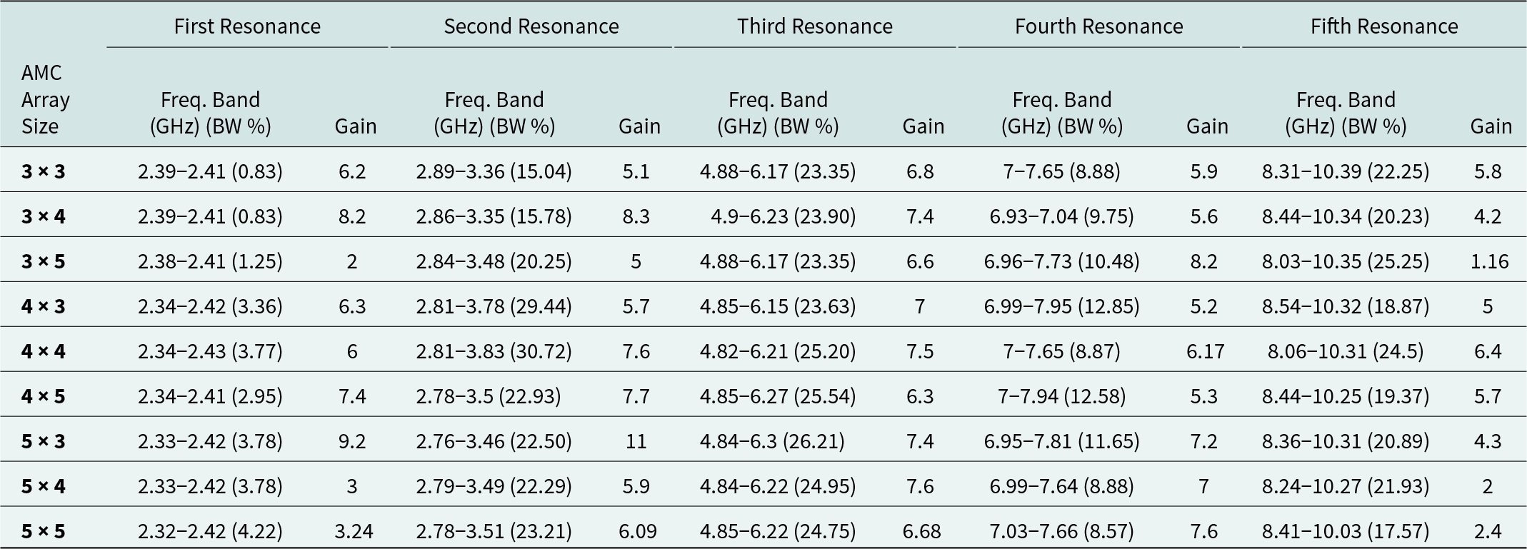
Depending on the antenna dimensions, the AMC array can range from 3 × 3 to 5 × 5. Irrespective of the array shape, the antenna is situated above the DANT-AMC distance and is centered relative to the AMC surface. All possible array sizes are depicted in Fig. 22, and Table 7 compares their gain and bandwidth at five different resonance frequencies. Even though the antenna’s reflection coefficients remain stable across a range of AMC array sizes, its performance improves significantly with increasing array size. At the first and last resonance frequencies, there is a minor gain reduction in a 5 × 5 array. To achieve a balance between reflection coefficients, integrated design size, gain, and production cost, the recommended AMC plane design employs a 4 × 4 unit cell, as shown in Fig. 23(b), which exhibits the reflection coefficient response for all AMC array size variations.

Figure 22. Antenna with different array size.
Table 7. Effects of different AMC array sizes on antenna gain and bandwidth (BW) at five resonance frequencies
The multiband antenna, situated at the height of DANT-AMC above the center of the AMC surface, is designed to provide coverage across a wide range of frequencies. Figure 23(a) illustrates the effects of varying the DANT-AMC parameter on the antenna’s performance. There is no denying that DANT-AMC has a significant impact on the impedance bandwidth of the AMC-backed antenna. The optimal distance is determined by varying the DANT-AMC parameter between 9 and 17 mm. A DANT-AMC of 13 or 15 mm enables the system to take advantage of the antenna’s multiband capabilities, with smaller values unable to cover the multiband response. By balancing radiation performance and profile requirements, a fair DANT-AMC value of 13 mm is determined to effectively cover most wireless frequency bands using the AMC-backed antenna.
Figure 24(a) shows the orientation angle of the antenna relative to the AMC plane. At the same time, Fig. 24(b) presents the reflection coefficients of the integrated design at various orientation angles denoted by the symbol “θ.” The orientation angle ranges from 0° to 90° in 15-degree increments. As a result, the integrated design generates a multiband response at frequencies of 2.5, 3.2, 5.5, 7.5, and 10 GHz, providing acceptable variation coverage. The antenna response at 0- and 90-degree orientation angles is identical due to the symmetrical AMC surfaces. Consequently, all orientations provide the same impedance bandwidth inside each band.

Figure 23. Reflection coefficient response (a) for different DANT-AMC and (b) for different array variation.

Figure 24. (a) The arrangement of orientation angles and (b) The reflection coefficient response for various orientation angles.
Analysis of integrated design performance in the presence of a human phantom
The distance between the antenna and a human phantom is a critical parameter to consider when designing WBAN antennas. In paper [Reference Chen, Liu, Fan and Yang8], the impact of this distance on antenna performance is studied, and it is recommended to maintain a gap of 3 mm between the antenna and the phantom to ensure optimal performance. Additionally, when designing antennas for use in WBANs, it is essential to evaluate their SAR to ensure they are safe for human use. The SAR quantifies the amount of electromagnetic power that the human body absorbs and can be used to determine whether a given antenna design poses any risk to human health. The SAR level is calculated using equation (8), where σ, ρ, and  $\vec E$ are tissue conductivity, mass density, and electric field, respectively.
 \begin{equation}{\textrm{SAR}} = {{\sigma {{\left| {\vec E} \right|}^2}} \over \rho }\end{equation}
Figures 25 and 26 present the simulated and measured reflection coefficient responses of the proposed antenna in the presence of a human phantom, comparing the cases with and without an AMC surface, respectively. The proposed antenna is suitable for off-body communication in WBAN applications. It can be used on purses and textile pockets as it is unaffected by human loading, thus ensuring the impedance bandwidth and gain remain stable. The SAR of the antenna is a critical factor to consider when designing wearable technology, and it is assessed using an HFSS simulation with a human phantom that includes a hand, arm, and leg with an input power of 100 mW. Figure 27 demonstrates the positioning of the antenna and AMC surface, placed within 3 mm of the phantom, as depicted in both the simulation and measurement setups. Figure 28 depicts the maximum and minimum SAR values at different resonant frequencies for various human phantom configurations. The average SAR values of the antenna without an AMC surface are illustrated in Fig. 28(a). Wearable technology must have SAR values of less than 1.6 W/kg. Figure 28(b) shows the cumulative SAR values with the presence of the AMC surface, which leads to a significant decrease in SAR. Table 8 reveals that the maximum SAR value drops from 18.7261 to 0.0627 W/kg when the AMC surface is included.

Figure 25. Simulated reflection coefficient response with human phantom: (a) Antenna without AMC and (b) antenna with AMC.

Figure 26. Measured Reflection coefficient response with human phantom: (a) Antenna without AMC and (b) antenna with AMC.

Figure 27. Measurement of antenna parameters with human phantom.

Figure 28. (a) Maximum SAR values without AMC and (b) Minimum SAR values with AMC.
Table 8. SAR values comparison of the proposed design

Table 9 presents a performance comparison between the proposed antenna and several existing antennas for off-body communication. Although most of the reviewed literature uses FR4 substrate materials, other materials are also discussed. The proposed antenna outperforms other antenna designs in the literature due to its multiband response and five different resonance frequencies. Although the first resonance has less impedance bandwidth, the proposed antenna is smaller than that in papers [Reference Pathan and Kakde5, Reference Saeed, Balanis, Birtcher, Durgun and Shaman28, Reference Gong, Yang, Li, Chen, Tong and Yu29] and comparable in size to papers [Reference Wang and Gao4, Reference Yang, Liu, Fan and Xiong18, Reference Yu, Yang, Chen and Zeng21, Reference Jiang, Wang, Nie, Zhao and Huang23], with even less thickness than in papers [Reference Yu, Yang, Chen and Zeng21, Reference Gong, Yang, Li, Chen, Tong and Yu29]. The proposed antenna also achieves a higher gain than all other antennas except papers [Reference Malekpoor, Abolmasoumi and Hamidkhani13, Reference Jiang, Wang, Nie, Zhao and Huang23], and has a maximum FBR of 31.5 dB at 6.01 GHz, exceeding all other papers except paper [Reference Chaouche, Nedil, Mabrouk and Ramahi6]. Furthermore, the proposed antenna has a lower maximum SAR than all other antennas, except paper [Reference Chaouche, Nedil, Mabrouk and Ramahi6]. The research paper demonstrates the use of metallic hexagonal patches for achieving multiband resonance on a single-layer patch, resulting in a simple and effective antenna design approach that achieves high gain, low SAR, high FBR, and increased bandwidth using a 4 × 4 AMC surface for off-body communication applications.
Table 9. Comparison with previous works

Conclusion
This study presents a novel multiband antenna design that utilizes a 4 × 4 AMC surface to achieve high gain and low SAR. The integrated antenna design covers a broad frequency range from 2 to 10 GHz and provides five resonant frequencies at 2.4, 3.2, 5.5, 7.5, and 10 GHz, and the AMC surface generates four zero-degree reflection phases. The design was simulated using ANSYS HFSS and validated using ADS software, and its performance results are confirmed through experimental verification by using a VNA and an anechoic chamber. The results show excellent performance, with a peak gain of 8.55 dBi and a high FBR of 31.5 dB. SAR simulations are performed using hand, arm, and leg phantoms, and the results indicate that the AMC surface effectively reduces SAR by 96.11%. AMC technology significantly reduces SAR levels and improves overall radiation efficiency by nearly 88%. The integrated design is ideal for off-body communication applications and potentially impacts the future of the wearable communication devices.
Acknowledgements
The authors would like to thank Mr. Susovan Ghosh, technical assistant of the National Institute of Technology Agartala, for his assistance in affixing the antenna to the AMC surface and SMA connector.
Author contributions
The research methodology, implementation, simulation, and manuscript preparation were spearheaded by R.V. D.G contributed significantly by providing conceptualization and offering supervision. The manuscript underwent collective review and writing efforts, with all authors making equal contributions to its refinement.
Funding statement
This research received no specific grant from any funding agency, commercial or not-for-profit sectors.
Competing interests
The authors report no conflict of interest.

Rajavel V received his M.E. degree in Communication and Networking in 2017 from Madras Institute of Technology Campus, Anna University, Chennai. Currently. he is pursuing Ph.D. from National Institute of Technology Agartala. He has 3.5 years of academic experience. His research interests are antenna design and networking.

Dr. Dibyendu Ghoshal received a Ph.D. (Tech) degree from Calcutta University’s Institute of Radio Physics and Electronics in 1997. He has more than 12 years of teaching experience. He is the author of more than 150 research articles. At the National Institute of Technology Agartala, he is an Associate Professor in the Electronics and Communication Engineering department. Microwave and millimeter wave technology and antenna engineering, digital signal and image processing with associated soft computing and optimization techniques, linear and nonlinear optics (along with photonics) and opto-electronics, semiconductor physics and devices, and digital signal processing are among his research and teaching interests.


