


Introduction
The explosive growth of mobile data and the widespread adoption of mobile phones have presented wireless service providers with unprecedented hurdles in overcoming a global bandwidth deficit [Reference Rappaport, Murdock and Gutierrez1, Reference Pi and Khan2]. Nowadays, cellular providers are confined to a carrier frequency range from 700 MHz to 2.6 GHz while seeking to provide wireless devices with low-latency video, high-quality, and multimedia services. The synchronized handling of several technologies that operate in the same finite band spectrum is required to service users with the older version of mobile phones as well as users with the latest smartphones. Currently, operator’s allocated spectrum is separated into discrete frequency bands, each having its radio network and propagation characteristics. As a result, base station designs need to handle various bands across several cell sites, with many base stations per cell site [3, 4]. Mobile broadband networks will have to keep up with the ever-increasing data rate demands of consumers, as well as deal with the expected exponential increase in traffic quantities. To meet the ever-increasing demands encountered by cellular carriers, it is necessary to have an effective radio access technology as well as more spectrum availability. The United States has adopted cellular communication systems which have evolved across four generations from around 1980, each successive generation arriving approximately every 10 years: in 1981, the first-generation analog frequency modulation FM cellular systems were released; in 1992, second-generation digital technologies were introduced; in 2001, 3G was introduced, followed by 4G LTE-A in 2011 [Reference Xichun, Gani, Salleh and Zakaria5]. Long-term evolution (LTE) is a radio-access technology that uses orthogonal frequency division multiplexing to provide an extensible transmission bandwidth of up to 20 MHz. Multiple-input multiple-output (MIMO) is an important technology for approving high data speeds in 5G networks, enabling multi-stream transmission for better spectrum utilization, enhanced connection quality, and adaptive beamforming for signal gain and reduction of interference by employing antenna arrays [Reference Molisch, Steinbauer, Toeltsch, Bonek and Thoma6–Reference Rajagopal, Abu-Surra, Pi and Khan8]. The scarce characteristics of propagation channels and a limited number of radio frequency (RF) chains at transceivers restrict the throughput of MIMO systems. The incorporation of reconfigurable antennas (RAs) allows for more flexibility in the design of MIMO systems [Reference Cetiner, Jafarkhani, Qian, Yoo, Grau and Flaviis9, Reference Grau, Jafarkhani and Flaviis10].
MIMO antenna
MIMO’s main advantages include fast data rate, low latency, and great communication reliability [Reference Hussain and Sharawi11]. The Internet of Things will soon allow machines, automobiles, and a variety of other wireless gadgets to communicate with one another. As a result, a robust wireless network that can handle enormous amounts of data and respond quickly is essential. The present research speed of the impending 5G [Reference Thompson, Ge, Wu, Irmer, Jiang, Fettweis and Alamouti12, Reference Thompson, Ge, Wu, Irmer, Jiang, Fettweis and Alamouti13], which has the approval of regulatory agencies, academia, and an industrial partnership, suggests that it is commercializing very fast [14]. High data rates, low latency transmission, enormous device connection, and increased channel capacity are all advantages of 5G technology. Fortunately, millimeter wave (mm-wave) frequencies with very short wavelengths are the best options for providing wide bandwidth, and small cell size for short-range connections, where massive antenna arrays/massive-MIMO may give several dedicated beams for different users. A well-thought-out strategy that optimizes each criterion simultaneously would yield a 1,000-fold improvement in the capability of 5G [Reference Wei, Hu, Qian and Wu15]. Over the last decade, making use of numerous antennas on both the receiver and the transmitter sides has gained popularity. However, there are several difficult criteria, including integrating the numerous MIMO antenna elements while keeping space, size, and performance limits in mind, reducing mutual coupling between firmly located antenna elements for improved efficiency and minimizing field coupling to reduce correlation amid different MIMO channels, enhancing diversity gain to boost wireless connection reliability and quality, and good overall reflection coefficient parameter to provide optimal bandwidth resilience. Among all the parameters which are considered during MIMO antenna design, degradation of mutual coupling amid the MIMO antenna elements is the most important factor. Some novel methods related to mutual coupling reduction have recently been reported. For the mutual coupling reduction between two antennas resonating in adjacent frequency bands, an antenna interference cancellation chip with a high-pass response is proposed in paper [Reference Zhao, Liu, Shen, Jing, Cai and Li16]. Two linear polarized antennas that are coupled in the H- and E-planes, respectively, are decoupled using meta-surface superstrates in paper [Reference Guo, Liu, Zhao, Yin, Huang and Li17]. To lessen the mutual couplings at two separate bands of two coupled MIMO antennas, a metasurface-based decoupling method is presented in paper [Reference Liu, Guo, Zhao, Huang, Li and Yin18]. For the purpose of reducing the mutual coupling of massive MIMO antennas, a double-layer metasurface was suggested. Furthermore, it was demonstrated that the decoupling superstrate contributed to the enlargement of the bandwidth and the restoration of the antenna array’s radiation patterns in paper [Reference Tang, Faraz, Chen, Zhang, Li, Li and Zhang19]. To decrease the mutual coupling between two tightly packed dipole antennas while retaining cross-polarization suppression, a ceramic superstrate-based decoupling method is presented in paper [Reference Liu, Guo, Zhao, Huang, Yingsong and Yin20].
Now readers have clear idea about some of the novel techniques for the reduction of mutual coupling which can be considered for the MIMO antenna design. In the following section, RAs, classification of RAs, and advantages/disadvantages of different techniques are discussed.
Reconfigurable antennas
RAs are required in current telecommunication systems because they may transmit several patterns at different frequencies and polarizations [Reference Haider, Caratelli and Yarovoy21]. Increased functionality within a constrained volume puts more strain on transceiver systems. This problem can be solved by using an RA [Reference Anagnostou, Chryssomallis and Goudos22]. Changing the radiation, frequency, or polarization characteristics of an antenna can be used to reconfigure it. Many strategies are used to adjust the electromagnetic radiations of the antenna’s effective aperture by redistributing the antenna currents [Reference Parchin, Basherlou, Al-Yasir, Abd-Alhameed, Abdulkhaleq and Noras23]. An RA can respond to alteration in external situations or system needs by altering their geometry and electrical behavior. The assimilation of RF-MEMS (microelectromechanical) systems, varactor diodes, PIN diodes, and photoconductive elements, the physical modifications of the antenna’s radiating structure, or the usage of smart materials like liquid crystals and ferrites, are all used in these reconfiguration techniques [Reference Parchin, Basherlou, Al-Yasir, Abdulkhaleq and Abd-Alhameed24]. Figure 1 shows the different techniques used to design the RA. Schaubert [Reference Schaubert, Farrar, Hayes and Sindoris25, Reference Smith26], filed in 1983, is the first patent on RA.

Figure 1. Different techniques used to design reconfigurable antenna [Reference Christodoulou, Tawk, Lane and Erwin27].
However, RF engineers must answer three difficult problems while developing RA: (1) Which reconfigurable property (e.g., radiation pattern, frequency, or polarization) should be changed? (2) How are the antenna structure’s various radiating elements adjusted to obtain the desired property? and (3) Which antenna reconfiguration technique has the least detrimental impact?
Reconfiguration techniques and classification of reconfigurable antennas
To develop an RA, different types of reconfiguration methods are used. RF-MEMS, PIN diode, and varactor diode, all come under the electrically RA. The advantages and disadvantages of different switching techniques are given in Table 1 [Reference Parchin, Basherlou, Al-Yasir, Abdulkhaleq and Abd-Alhameed24]. Antennas that use photoconductive switching elements are known as an optically RA. The technique which includes physical modification of the antenna structure comes under the physically RA. The last category of the RA is designed using smart materials like ferrites and liquid crystals. The advantages and disadvantages of different reconfigurable techniques are given in Table 2 [Reference Parchin, Basherlou, Al-Yasir, Abdulkhaleq and Abd-Alhameed24]. Apart from these, RA can also be categorized into major categories like frequency RA, polarization RA, radiation pattern RA, and a combination of any of the above reconfigurable techniques. All the reconfigurable technologies can be achieved by alterations in the direction of the surface current, modification in the feeding structure, modification in the physical structure of the antenna, or by changing antenna radiating elements [Reference Rutschlin and Sokol28]. However, a designer must consider or monitor the effect of change in one parameter on the others. Apart from complexity in designs, some notable advantages dominate the wireless industry like minimal cost, reduction in space requirements, isolations from other wireless devices, ability to adapt according to requirements, etc. During the designing of the RA, RF engineers should try to minimize the cost of biasing the network structure used to activate or deactivate the switching elements. Power consumption in active components should also be minimized.
Table 1. Advantages and disadvantages of different switching techniques

Table 2. Advantages and disadvantages of different reconfigurable techniques

In the previous two sections, MIMO antennas and RAs are discussed in brief. The main purpose of this review article is to give insight of the history of the Reconfigurable MIMO antenna and how it gets evolved through the years. The detailed literature review has been done to through the light on it and to make it easier for the young researchers who want to work on reconfigurable MIMO antenna designs for the mm-wave frequencies.
Reconfigurable MIMO antennas
Reconfigurable MIMO antennas have received a lot of interest because of their capability to operate in different frequency bands, to have different polarizations, and pattern diversity and also it keeps up with the ongoing research and development on 5G networks. Because of its potential to reduce the size of front-end systems, avoid interference with other wireless systems, and increase throughput, RAs have piqued the interest of researchers and industry. Several approaches for reconfiguration have been proposed by antenna designers. The use of parasitic elements in a novel form of MIMO antenna is presented in paper [Reference Migliore, Pinchera and Schettino29]. After discussing a suitable model for the parasitic-MIMO system, computational and experimental research is conducted. The findings demonstrate that the suggested strategy can greatly boost communication system performance while having a negligible effect on system complexity and cost. In paper [Reference Sayeed and Vasanthan30], research is done on to how RA arrays affect MIMO wireless communication connection’s capacity maximization in sparse multipath situations. The advantages of employing pattern-RAs in MIMO communication systems are examined in paper [Reference Boerman and Jennifer31]. A wideband performance investigation is done in paper [Reference Pinchera, Wallace, Migliore and Jensen32], using an experimental measurement approach for an adaptive MIMO antenna with two active and six parasitic antenna elements. A flexible technique for increasing line-of-sight (LOS)-MIMO capacity at any operating signal-to-noise ratio (SNR) is proposed in paper [Reference Matthaiou, Sayeed and Nossek33]. The theoretical and numerical findings show that large capacity improvements can be achieved by merely varying the antenna spacing as a function of SNR.
A detailed literature review has been done on the different classifications of reconfigurable MIMO antenna, and some of them are mentioned in the following section.
Frequency-reconfigurable MIMO antenna
Antennas that switch between discrete frequencies or span a broad spectrum of frequencies are known as frequency-agile or frequency RA. Compact antennas with limited instantaneous bandwidths can be modified to function across a wider range of frequencies by constructing antennas with frequency agility, resulting in a performance that is effective for a larger bandwidth. To give an insight into the different techniques opted to design frequency-reconfigurable MIMO antennas, some of them are discussed in papers [Reference Lim, Back, Ko, Song and Yun34–Reference Nikam, Kumar, Sivanagaraju and Baidya66]. A reconfigurable planar inverted-F antenna (PIFA) with a fine-tuning varactor and switchable PIN diode is given in paper [Reference Lim, Back, Ko, Song and Yun34]. The RA system in paper [Reference Hu, Hall, Gardner and Nechayev35] is able to generate three tunable resonant frequencies simultaneously. The MIMO antenna in paper [Reference Hu, Hall and Gardner36] delivers higher than 15 dB isolation in two working bands – 646–848 and 1648–2074 MHz. As a result, the antenna can cover important cellular services such as LTE700, GPS, GSM1800, and PCS 1900. The resonant frequency in paper [Reference Jin, Lim and Yun37] is switched among the wireless local area network (WLAN) band (2400–2483 and 5150–5350 MHz) and the m-WiMAX band (3400–3600 MHz) depending on the different states of the PIN diode. The digital TV (DTV) antenna in paper [Reference Kulkarni and Sharma38] is matched between 496 and 862 MHz, whereas LTE bands 3 and 7 are matched between 1710–1880 and 2500–2700 MHz, respectively. To achieve the MIMO antenna system reconfigurability in paper [Reference Hussain and Sharawi39], two modes of selection are utilized. Varactor diodes are tuned to span the frequency over a broad range, notably at frequencies below 1 GHz. The sensing antenna spans over a wide frequency range starting at 720–3440 MHz. The sensing antenna in paper [Reference Hussain and Sharawi40] is capable of covering a large frequency range from 710 to 3600 MHz. The MIMO antenna structure spans a broad range of frequencies, from 755 to 3450 MHz. There are two types of cognitive radio (CR) antenna systems are detailed in paper [Reference Tawk, Costantine and Christodoulou41]. In both situations of CR, reconfigurable filtennas are designed as communicating antennas in a MIMO scenario as shown in Fig. 2(a) and (b). The wideband antenna in paper [Reference Cheng and Lin42], located at the center, serves as a framework for improving the isolation of two monopoles. The antenna system in paper [Reference Hussain and Sharawi43] is a four-element MIMO antenna with dual-mode as shown in Fig. 2(c). Below 1 GHz, it spans a large frequency range. This approach is suitable for use in wireless handheld devices that use CR. Two symmetrical frequency-reconfigurable monopole elements and frequency-reconfigurable defected ground structure (DGS) make up the antenna in paper [Reference Cao, Cheung and Yuk44]. The monopole elements are divided into two portions, section 1 and section 2, which are joined by a PIN diode. Section 1 gives a 2.26 GHz. Sections 1 and 2 will be joined together when the PIN diode is turned on, resulting in a low-frequency band of 1.93 GHz. To provide isolation between monopole elements, DGS is utilized. The antenna in paper [Reference Soltani, Lotfi and Murch45] can be configured to give four ports that operate from 4.9 to 5.75 GHz with greater than 14 dB isolation between antennas. It also has two ports functioning at 2.4–2.5 GHz and two ports working at 4.9–5.725 GHz, having isolations of more than 18 dB. The antenna elements in paper [Reference Hussain and Sharawi46] are loaded with capacitive reactance utilizing varactor diodes to produce frequency agility. The MIMO antenna with a broad range of adjustability of 1610–2710 MHz covers several prominent wireless protocols. Each tuned band has a minimum bandwidth of 470 MHz. To achieve frequency reconfigurability, the proposed antenna in paper [Reference Raza, Khan, Hussain, Tahir and Sharawi47] comprises compact patch antenna elements and varactor diodes. The antenna offers a 50 MHz bandwidth and it is reconfigured from 2.1 to 2.4 GHz. An ultrawideband (UWB) quasi-omnidirectional antenna in paper [Reference Nachouane, Najid, Tribak and Riouch48] is utilized to fulfill the sensing operation and a narrowband antenna is utilized to perform the communication task. The sensing antenna is capable of operating in a broad range of frequency bands, from 2 to 5.5 GHz. The resonance frequency of the communication antenna is modified from 2.6 to 2.7 GHz. The frequency-agile antenna in paper [Reference Hussain, Ghalib and Sharawi49] has a large tuning range and can operate with a variety of wireless technologies, like GSM1800/LTE/UMTS/WLAN. The frequency of resonance spans between 1.8 and 2.45 GHz. Every antenna element comprises circular and annular slots, with a varactor diode in the annular slot allowing the antenna to be reconfigured. Mobile terminals, wireless portable gadgets, and CR front-ends can benefit from the proposed approach. The inverted-F antenna (IFA) in paper [Reference Hussain, Khan and Sharawi50] spans over the WLAN band, and the circular slots serve as an isolation improvement structure for the two IFA parts (shown in Fig. 2(d)). The annular slots are also configured throughout a range of frequencies from 1.73 to 2.28 GHz, having a bandwidth of 60 MHz. Varactor diodes are used to make the slots reconfigurable. For WWAN/LTE smartphones, a reconfigurable MIMO antenna which is full metal-rimmed is designed in paper [Reference Xu, Sun, Zhou, Ban, Li and Ang51]. Four resonant modes are generated by the antenna elements, and the coupled feed is offered by a U-shaped feeding line. A smartphone antenna with a reconfigurable MIMO antenna is presented in paper [Reference Zhang, Yang, Ban, Qiang, Guo and Z-f52]. On the top and bottom edges of the ground, the given antenna has four monopole slots engraved into it. The two long monopole slots have the potential to generate the needed lower-band (824–960 MHz) when the two PIN diodes are turned off, which is used as 2 × 2 MIMO system. The required upper-band (1710–2690 MHz) can be excited by the four ports, which can be employed as a 4 × 4 MIMO antenna. A dual-band MIMO antenna in paper [Reference Raza, Khan, Tahir, Hussain and Sharawi53] is reconfigured using a varactor diode which is integrated through the slot. To improve isolation, DGS is employed in the middle of the antenna elements. The design is appropriate for CR-enabled platforms and LTE systems because of its low envelope correlation coefficient and compact size. Four PIN diodes are utilized to design a frequency-reconfigurable MIMO antenna in paper [Reference Pandit, Mohan and Ray54], which is applicable for a wireless sensor network. To the ground plane, it has a U-shaped metallic strip and inverted-T slot as shown in Fig. 3(a). This antenna is appropriate for incorporation into mobile electronic devices built for numerous sensing applications, such as temperature detection, due to its small size, and low mutual coupling. Varactor diodes are used to make the proposed tri-band antenna design in paper [Reference Hussain, Sharawi and Shamim55] have ultrawide reconfigurable (shown in Fig. 3(b)). With the tri-band operation, a change in resonance frequencies is recorded from 1.32 to 1.49 and 1.75 to 5.2 GHz. The proposed method of designing an antenna is highly suitable for CR platforms in mobile terminals and wireless portable devices. With dual-band features, MIMO antenna in paper [Reference Zhao and Riaz56] has large frequency reconfigurability spanning over 1.3–2.6 GHz (shown in Fig. 3(c)). In the feedline, a varactor diode is used to reconfigure the dual-band antenna. The two-port antenna in paper [Reference Zhao, Riaz and Geng57] is based on a printed monopole antenna with a modified triangular shape. The antenna can operate in both sensing and reconfigurable communication modes without interfering with one another’s properties. Utilizing PIN diode switching, the suggested antenna spans over the frequencies from 1 to 4.5 GHz in UWB mode, and with the help of varactor diode tuning, it can provide a broad range of reconfigurable frequencies from 0.9 to 2.6 GHz. A small quad-element MIMO antenna is given in paper [Reference Hussain, Khan, Almajali and Sharawi58]. There are four annular slots and a rectangular slot is included in the annular slot to enhance its electrical length and lower the resonance frequency. Every element comprises an split-ring resonator (SRR) that allows for the reduction in size and multi-band operation at various frequencies. The UWB antenna in paper [Reference Hussain and Sharawi59] has a frequency range of 1.48–4.56 GHz. For multiband operation, the four-element frequency-reconfigurable MIMO antenna uses SRR loadings. It spans the frequency range of 1.495–2.18, 3.35–4.08, and 4.15–4.49 GHz. The antenna design described is applicable for PC on second-generation CR systems. Two antenna elements are arranged in an H-shape as shown in Fig. 4(a), given in paper [Reference Hussain, Khan and Sharawi60]. Meandering slot-line and reactive loading miniaturized techniques are used so that antenna can be operational for sub 1 GHz bands. The proposed antenna covers the majority of the standard communication protocols. The bottom layer ground plane has four antenna components in paper [Reference Hussain and Sharawi61], each with an annular slot and a circular slot separated outwardly from the circular slot and extending circumferentially around it. Each antenna element has a microstrip feed line in the bottom layer. In the uppermost layer, varactor diodes cover the width of each annular slot, allowing the resonance frequency to be tuned throughout a large operating band. A dual-band, slot-based frequency-reconfigurable MIMO antenna, as shown in Fig. 4(b), is given in paper [Reference Hussain62]. Every element is made up of concentric annular slots which are loaded reactively using varactor diodes. All of the tuned bands are controlled by precise diode placement and optimal biasing circuit setup. A slot-based complementary wideband reflector element is used to make a slot antenna’s omnidirectional pattern directional (illustrated in Fig. 4(c) and (d)). This MIMO antenna [Reference Jehangir, Hussain, Hussein and Sharawi63] design spans over LTE and WiMAX frequencies having measured bandwidth of 200 MHz for each covered band. It can be used with tablet portable devices as well as access points. The Yagi-like MIMO system in paper [Reference Hussain, Jehangir, Khan and Sharawi64] uses four similar active antenna elements that are connected with varactor diodes to acquire frequency reconfigurability around 1.5–2.1 GHz (shown in Fig. 5(a)). This approach is unique as it achieves Yagi-like directional properties over a large frequency range. A parasitic metallic reflector layer beneath the substrate transforms a slot antenna’s traditional omnidirectional pattern into a directional one. Back-lobe radiation is greatly diminished when the reflector element is used, and a front-to-back ratio of 5–13 dB is obtained across the full range of frequencies. A varactor diode having a frequency tunability range of 1655–2605 MHz is used to produce frequency reconfigurability in paper [Reference Hussain, Khan, Iqbal, AlMajali, Alja’Afreh, Johar, Shamim and Sharawi65]. The MIMO configuration’s two slot antenna elements are etched out of a ground plane. A dual-band reconfigurable MIMO antenna for fifth-generation 3.5 GHz and ISM 5.2 GHz, as shown in Fig. 5(b), is described in paper [Reference Nikam, Kumar, Sivanagaraju and Baidya66]. To achieve dual-band functioning, the described antenna employs the partial ground plane (PGP) DGS approach and PIN diode integrated branch lines. In addition, without DGS, the intermediate structure is operational in a wideband to narrowband reconfigurable mode.

Figure 2. (a) The top layer structure and the bottom layer structure of a MIMO-based antenna system are intertwined [Reference Tawk, Costantine and Christodoulou41], (b) The MIMO antenna system’s top and bottom layers [Reference Tawk, Costantine and Christodoulou41], (c) Views of a four-element MIMO antenna system from the top and bottom [Reference Hussain and Sharawi43], (d) MIMO antenna system’s top layer and ground plane [Reference Hussain, Khan and Sharawi50].

Figure 3. (a) Top and bottom perspectives of frequency-reconfigurable MIMO antenna [Reference Pandit, Mohan and Ray54], (b) Views of the MIMO antenna system from the top and bottom [Reference Hussain, Sharawi and Shamim55], (c) The layout of the four-port frequency-reconfigurable MIMO antenna [Reference Zhao and Riaz56].

Figure 4. (a) Top layer and ground plane of MIMO antenna [Reference Hussain, Khan and Sharawi60], (b) Top view and Bottom view [Reference Hussain62], (c) and (d) Top layer and ground plane of MIMO antenna [Reference Jehangir, Hussain, Hussein and Sharawi63].
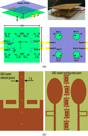
Figure 5. (a) MIMO antenna system: Simulated model, Fabricated antenna, Top view, and Bottom view [Reference Hussain, Jehangir, Khan and Sharawi64], (b) Design of the EBG-loaded MIMO antenna [Reference Nikam, Kumar, Sivanagaraju and Baidya66].
Other reconfigurable MIMO antennas
A spiral antenna that can be reconfigured to work with adaptive MIMO systems. The antenna has the ability to reconfigure the polarizations of the radiated field [Reference Cetiner, Qian, Li and De Flaviis67]. In this study, pattern- and polarization-reconfigurable, a single-turn square spiral microstrip antenna for the 5 GHz indoor band is proposed and tested using CMOS MIMO transceivers made by Intel [Reference Pan, Huff, Roach, Palaskas, Pellerano, Seddighrad, Nair, Choudhury, Bangerter and Bernhard68]. The radiation pattern and mutual coupling are afflicted by the switch configuration, resulting in differing degrees of pattern diversity that will be employed for boosting the connection capacity in paper [Reference Piazza, Kirsch, Forenza, Heath and Dandekar69]. On the basis of which arms are alternated into the current path, the RA can provide polarization and pattern diversity [Reference Raj, Bonney, Herrero and Schoebel70]. A miniaturized 2-port dual-linearly polarized RA design is discussed in paper [Reference Grau, Romeu, Lee, Blanch, Jofre and De Flaviis71]. The antenna’s polarization base can be rotated from vertical to horizontal by switching between two different linear polarization bases. It is built on a quartz substrate and shifts between the two polarization bases using monolithically integrated MEMS switches. The proposed antenna has two points of interest. First, the antenna can track polarization in LOS situations when using polarization-sensitive communication techniques. Second, it can be applied to boost the diversity order or gain in non-LOS circumstances of a MIMO communication system using orthogonal space–time block codes. A miniaturized RA array applicable for the UMTS spectrum is given in paper [Reference Li, Du and Gong72]. Two hybrid-monopole and dipole elements make up the antenna array. Monopole and dipole are two modes of operation for each antenna element, which are managed by the three different states of PIN diodes. Hence, there are four modes in the proposed antenna array. These four modes describe four alternative radiation patterns that can accomplish pattern reconfigurability to enhance the channel capacity for the various channel scenarios. A novel reconfigurable MIMO slot antenna in paper [Reference Mubasher, Wang, Chen and Ying73] will enable pattern diversity and boost system performance. PIFA is utilized to design MIMO antenna to reconfigure it at three different bands in paper [Reference Lim, Jin, Song and Yun74]. The suggested antenna concurrently acquires the reconfigurability in frequency and isolation over the three ranges of m-WiMAX bands. Low-loss RF switches allow the array pattern to be reconfigurable at an angle of 0°, 70°, and 290° in the azimuth plane in paper [Reference Chamok, Yılmaz, Arslan and Ali75] (shown in Fig. 6(a)). However, narrow elevation plane beam width and high peak gain are achieved by collinear geometry. With the help of the reconfigurable UWB MIMO antenna in paper [Reference Khan, Iftikhar, Shubair, Capobianco, Asif, Braaten and Anagnostou76], as illustrated in Fig. 6(b), the range of frequencies from 4.9 to 6.3 GHz will be rejected. The PIN diode is used with each radiator so that an LC stub is linked with the ground plane. Two radiators are arranged at an angle of 90° with each other to make use of the polarization diversity.

Figure 6. (a) Array geometry, top view, and front view of a single subarray [Reference Chamok, Yılmaz, Arslan and Ali75], (b) View of the UWB MIMO antenna from an angle [Reference Khan, Iftikhar, Shubair, Capobianco, Asif, Braaten and Anagnostou76].
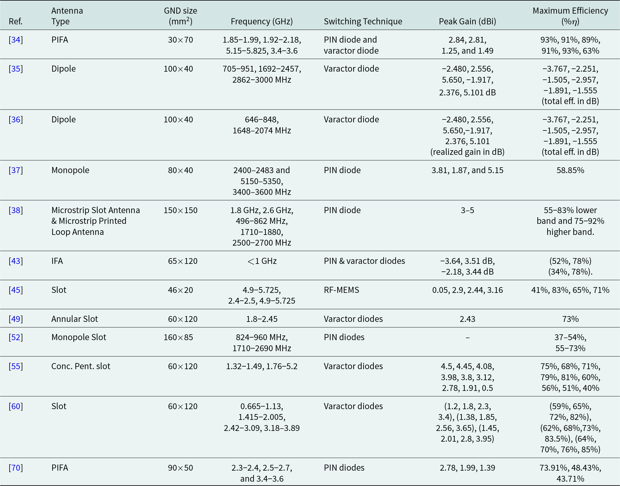
A comparison table (Table 3) is also given to give insight of improvement over the years. Using a varactor and a PIN diode, a reconfigurable PIFA is proposed in paper [Reference Lim, Back, Ko, Song and Yun34]. The antenna can choose a very distinct frequency band on the basis of PIN diode on and off status amidst radiating elements. A novel approach to reconfiguring a balanced antenna is presented in paper [Reference Hu, Hall, Gardner and Nechayev35]. The matching network and balun designs are jointly tuned to reduce the component count. The wideband reconfigurable MIMO antenna that is being presented in paper [Reference Hu, Hall and Gardner36] combines a two-port chassis antenna with a reconfigurable balanced dipole. Within the operational ranges, the suggested MIMO antenna offers minimal correlation and excellent efficiency. This paper [Reference Jin, Lim and Yun37] introduces a high isolation frequency-reconfigurable MIMO antenna. Operating frequency bands can be interchange between WLAN and m-WiMAX based on the PIN diode on/off states. For usage in portable wireless DTV media players, a planar internal antenna for the DTV band and a frequency-reconfigurable MIMO antenna encompassing the LTE bands have both been proposed in paper [Reference Kulkarni and Sharma38]. The dual-band reconfigurable planar antenna in paper [Reference Hussain and Sharawi43] is mostly appropriate for small wireless portable devices for CR applications and covers several frequency bands below 1 GHz. The two new reconfigurable slot elements that make up the reconfigurable structure in paper [Reference Soltani, Lotfi and Murch45] are arranged back-to-back and can operate in the 2.4 or 5 GHz bands, depending on the states of the MEMS switches inserted into the slots. In order to accomplish frequency reconfigurability [Reference Hussain, Ghalib and Sharawi49], varactor diodes are best positioned on one side of each annular slot which covers a wide range of well-known wireless standards from 1.8 to 2.45 GHz. While two PIN diodes are OFF, the suggested antenna [Reference Zhang, Yang, Ban, Qiang, Guo and Z-f52] can be utilized as a 2 × 2 MIMO antenna in the 824–960 MHz band. When these two diodes are ON, the proposed antenna can be used as a 4 × 4 MIMO system for the 1710–2690 MHz band. Varactor diodes were used to make the proposed triband antenna design ultrawide configurable, with a gradual shift in resonance frequencies was seen [Reference Hussain, Sharawi and Shamim55]. By reactively loading the slot, quad-band RA was proposed using a single varactor diode [Reference Hussain, Khan and Sharawi60]. This research [Reference Raj, Bonney, Herrero and Schoebel70] proposes a two-channel frequency-reconfigurable MIMO antenna with switchable isolation properties for three m-WiMAX bands.
Table 3. Comparison table for the different reported papers
Conclusion and future aspects of reconfigurable MIMO antenna
MIMO is a critical technology for approving high data speeds in 5G networks, allowing multi-stream transmission for increased spectrum efficiency, enhanced connection quality, and adaptive beamforming for signal gain and reduction of interference by employing antenna arrays [3–Reference Xichun, Gani, Salleh and Zakaria5]. Millimeter-wave communications appear to be a good candidate for forthcoming wireless networks to handle the demands of increasing mobile traffic. There are some critical factors for enabling mm-wave communications in upcoming 5G wireless communication networks [Reference Molisch, Steinbauer, Toeltsch, Bonek and Thoma6], such as signal attenuation due to free space propagation, atmospheric gases, and rain. Overall, mm-wave communications are expected to be a key component of the 5G era [Reference Fuhl, Molisch and Bonek7]. The incorporation of RAs allows for more flexibility in the design of mm-wave MIMO systems. MIMO technology is important for increasing the capacity of communication systems since it allows several antennas to operate at the same time. As a result, the data rate, capacity, and dependability of the communication link are all improved. As wide bandwidth is necessary for concurrent operation in fifth-generation MIMO antennas, while the high gain is necessary to limit atmospheric diminutions and absorptions at mm-wave frequencies, and compactness of structure is necessary to simplify assimilation in MIMO systems. Apart from this, constructing antenna components that are closely packed with low mutual coupling and better isolation, which will increase antenna performance, is one of the issues connected with MIMO antenna design. Therefore, RAs have received a lot of interest because of their capability to operate in different frequency bands and to keep up with the ongoing research and development on mm-wave antennas for 5G networks.
In this review article, a thorough survey about the reconfigurable MIMO antenna is given. It includes different types of reconfiguration techniques used to design the reconfigurable MIMO antenna. Advantages and disadvantages of different reconfigurable techniques are also discussed. This study also elaborates the earlier proposed reconfigurable MIMO antenna started from 2005 to 2022. A comparison table (Table 3) is also given to give insight of improvement over the years. Future smart RA will likely be fully multipurpose and controlled by software and equipped with machine learning skills that can discern and respond to alterations in the RF environment. CR utilizations will be accomplished using a new generation of antenna technology and communication protocols. The effective use of frequencies, as well as the use of polarization diversity and radiation pattern reconfigurability to send data over existing congested frequencies, will be major advantages for such applications. According to recent studies, for wireless communications, mm-wave frequencies could be used in addition to the currently congested radio spectrum regions. At mm-wave frequency ranges, the combination of reconfigurable approaches with MIMO technology enhances the efficiency of mm-wave wireless communications. Furthermore, mm-wave carrier frequencies enable wider bandwidth allocations, resulting in faster data transfer rates. Because of the shorter wavelength, mm-wave frequencies may take use of polarization and novel spatial processing techniques like massive MIMO and adaptive beamforming.
Competing interests
The authors declare that they have no known competing financial interests or personal relationships that could have appeared to influence the work reported in this paper.

Puja Kumari received her BTech degree in Electronics and Communication Engineering and MTech degree in Wireless Communication Engineering from BIT MESRA, Ranchi, Jharkhand (India) in the years 2011 and 2014, respectively. She has received her Ph.D. degree from NIT Durgapur, West Bengal (India) in 2021. Currently, she is working as a postdoctoral fellow in IIT (ISM), Dhanbad, Jharkhand (India) from April 2022. Her research interest lies in the area of MIMO antenna and filter design.

Santanu Dwari (Senior Member, IEEE) received the BTech and MTech degrees in Radio Physics and Electronics from the University of Calcutta, West Bengal, India, in 2000 and 2002, respectively, and the PhD degree from the Indian Institute of Technology, Kharagpur, India, in 2009. In 2008, he joined the Department of Electronics Engineering, Indian Institute of Technology (ISM), Dhanbad, India, as an assistant professor. He is currently an associate professor in the Department of Electronics Engineering, Indian Institute of Technology (ISM), Dhanbad, India. He has published more than 125 research articles in refereed international journals. His current research interest includes computational electromagnetics, antennas, and RF planar circuits.


