


1. Introduction
The interaction between an airflow and a film of viscous fluid on a solid substrate is a fundamental problem in fluid mechanics, not only because of its intrinsic scientific interest, but also because of its relevance to a wide range of practical situations. For example, the interaction between the wind and the rivulets of rainwater that form on the cables of cable-stayed bridges on wet and windy days is believed to play a key role in the potentially damaging rain–wind-induced vibrations of such cables (Lemaitre, Hémon & de Langre Reference Lemaitre, Hémon and de Langre2007; Robertson et al. Reference Robertson, Taylor, Wilson, Duffy and Sullivan2010; Taylor & Robertson Reference Taylor and Robertson2011, Reference Taylor and Robertson2015; Gao et al. Reference Gao, Chen, Eloy and Li2018), the interaction between the airflow within and the film of oil on the inside of the outer shaft of the bearing chamber in a rapidly rotating aeroengine is an important aspect of the overall performance of the engine (Farrall et al. Reference Farrall, Simmons, Hibberd and Gorse2006; Noakes, King & Riley Reference Noakes, King and Riley2011; Williams et al. Reference Williams, Hibberd, Power and Riley2012; Kay, Hibberd & Power Reference Kay, Hibberd and Power2015; Nicholson et al. Reference Nicholson, Power, Tammisola, Hibberd and Kay2019), the jet-wiping (or air-knife) coating process in which impinging jets of air are used to control the thickness of a fluid film on a moving substrate (Barreiro-Villaverde, Gosset & Mendez Reference Barreiro-Villaverde, Gosset and Mendez2021; Mendez et al. Reference Mendez, Gosset, Scheid, Balabane and Buchlin2021), while a film of fluid on a rotating cylinder in an airflow is a key component of a recently proposed method for applying pesticides to crops using minimal amounts of chemical and with minimal drift (Newell & Viljoen Reference Newell and Viljoen2019).
In order to gain further insight into such complex and multi-faceted problems, in the present work we investigate the effect of a non-uniform pressure distribution due to an irrotational airflow with circulation on coating flow, i.e. on the flow of a thin film of a viscous fluid on the outside of a uniformly rotating horizontal circular cylinder. Following the now-classical work on coating flow by Moffatt (Reference Moffatt1977) and Pukhnachev (Reference Pukhnachev1977), there has been a large body of work on many different aspects of coating flow and/or the closely related problem of rimming flow (i.e. the corresponding flow on the inside of the cylinder) in the absence of an airflow. These two problems have been the subject of many notable previous studies, including the pioneering numerical investigation of coating flow by Hansen & Kelmanson (Reference Hansen and Kelmanson1994), the study of the critical solution in coating and rimming flow by Wilson, Hunt & Duffy (Reference Wilson, Hunt and Duffy2002), the study of the effect of surface tension in rimming flow by Ashmore, Hosoi & Stone (Reference Ashmore, Hosoi and Stone2003), the series of studies on the subtle long-time dynamics of coating flow by Hinch & Kelmanson (Reference Hinch and Kelmanson2003), Hinch, Kelmanson & Metcalfe (Reference Hinch, Kelmanson and Metcalfe2004), Kelmanson (Reference Kelmanson2009) and Groh & Kelmanson (Reference Groh and Kelmanson2014), the numerical investigations of two- and three-dimensional coating flow by Evans, Schwartz & Roy (Reference Evans, Schwartz and Roy2004, Reference Evans, Schwartz and Roy2005), the study of a ring of fluid in coating and rimming flow by Leslie, Wilson & Duffy (Reference Leslie, Wilson and Duffy2013), the bifurcation analysis of coating flow by Lin et al. (Reference Lin, Rogers, Tseluiko and Thiele2016), the investigation of coating flow on topographically patterned and elliptical cylinders by Li, Carvalho & Kumar (Reference Li, Carvalho and Kumar2017a,Reference Li, Carvalho and Kumarb), the discovery of new branches of steady solutions in coating and rimming flow by Lopes, Thiele & Hazel (Reference Lopes, Thiele and Hazel2018) and the formulation and analysis of a ‘thick-film’ model for coating flow by Wray & Cimpeanu (Reference Wray and Cimpeanu2020). In particular, Moffatt (Reference Moffatt1977) showed that (in the absence of both surface-tension and inertia effects) steady, two-dimensional, continuous and strictly positive solutions corresponding to a continuous film of fluid covering the entire cylinder, hereafter referred to as ‘full-film’ solutions, are possible only below a critical maximum load (or, equivalently, only below a critical maximum azimuthal volume flux). Somewhat counterintuitively, the azimuthal velocity of the film in these full-film solutions is always in the same direction as the rotation of the cylinder, and the streamlines of the flow (including the free surface of the film) always have top-to-bottom (but not right-to-left) symmetry. Note that other kinds of solutions, specifically discontinuous ‘jump’ solutions with one or more shocks or jumps (Johnson Reference Johnson1988) and ‘curtain’ solutions which are unbounded at the top and the bottom of the cylinder (Duffy & Wilson Reference Duffy and Wilson1999), are also possible, but in the present work we restrict our attention to full-film solutions.
There has, however, been a great deal less work on the effect of an airflow on coating and/or rimming flow. Both Black (Reference Black2002) and Villegas-Díaz, Power & Riley (Reference Villegas-Díaz, Power and Riley2003) modelled the effect of the airflow as a uniform shear stress on the free surface of the film and independently discovered that, in addition to a branch of full-film solutions connected to and qualitatively similar to that in the absence of an airflow, a second branch of full-film solutions, which is disconnected from and qualitatively different from that in the absence of an airflow, exists when the shear stress is sufficiently strong and acts in opposition to the rotation of the cylinder. In addition, Villegas-Díaz et al. (Reference Villegas-Díaz, Power and Riley2003) and Villegas-Díaz, Power & Riley (Reference Villegas-Díaz, Power and Riley2005), the latter of whom also included surface tension, considered the existence, uniqueness and stability of jump solutions. In a series of follow-up papers, Kay, Hibberd & Power (Reference Kay, Hibberd and Power2013, Reference Kay, Hibberd and Power2014), Kay et al. (Reference Kay, Hibberd and Power2015) and Nicholson et al. (Reference Nicholson, Power, Tammisola, Hibberd and Kay2019) extended this work to include fluid inertia, thermal effects, an additional mass flux due to droplets impacting on the free surface of the film and slip at the surface of the cylinder. Also relevant here is the work on the effect of an airflow on thin-film flow on a stationary cylinder by Lemaitre et al. (Reference Lemaitre, Hémon and de Langre2007) and Robertson et al. (Reference Robertson, Taylor, Wilson, Duffy and Sullivan2010), who modelled the effect of the airflow as prescribed pressure and shear stress distributions on the free surface of the film, and by Taylor & Robertson (Reference Taylor and Robertson2011, Reference Taylor and Robertson2015), who computed the airflow numerically using the Discrete Vortex Method, as well as that by Paterson, Wilson & Duffy (Reference Paterson, Wilson and Duffy2014) on the flow of a slowly varying rivulet around a stationary cylinder in the presence of a uniform surface shear stress and those by McHale, Flynn & Newton (Reference McHale, Flynn and Newton2011) and Gruncell, Sandham & McHale (Reference Gruncell, Sandham and McHale2013) on a thin layer of gas trapped on the surface of a stationary sphere in a flow of a viscous fluid.
In the present work we undertake the first detailed analysis of steady coating flow in the presence of a non-uniform pressure distribution due to an irrotational airflow with circulation. This problem is not only of interest in its own right, both as a rare example of an analytically tractable problem involving the interaction between an airflow and a fluid film and as a novel extension to the extensively studied classical coating-flow problem, but also as a paradigm for the wide range of practical situations, including those mentioned above, in which a thin film of fluid on a moving solid substrate is subject to an airflow.
2. Governing equations
Consider steady two-dimensional coating flow of a thin film of incompressible viscous fluid on a horizontal circular cylinder of radius  $a$ rotating anticlockwise with uniform angular speed $\varOmega \ (>0)$ in the absence of surface-tension effects but in the presence of a steady two-dimensional airflow. The air is taken to be incompressible and inviscid, so that there is a non-uniform pressure (but no shear stress) on the free surface of the film due to the airflow, the film being supported on the cylinder against gravity by a combination of the shear that is induced by the rotation of the cylinder and the air pressure on the free surface of the film. We assume that, since the film is thin, the airflow is unaffected by the presence of the film. Specifically, following Newell & Viljoen (Reference Newell and Viljoen2019), we take the airflow to be irrotational with uniform horizontal velocity $U_\infty$ from left to right and pressure $p_\infty$ in the far field and a circulation $\kappa$ (measured anticlockwise) round the cylinder, as sketched in figure 1. The air pressure on the free surface of the film, $p_{a} = p_{a}(\theta )$, is therefore given by the classical expression
 \begin{equation} p_{a} = p_\infty + \frac{\rho_{a}}{2}\left[U_\infty^2 - \left(2U_\infty\sin\theta - \frac{\kappa}{2{\rm \pi} a}\right)^2\right], \end{equation}
where  $\rho _{a}$ denotes the constant density of the air and $\theta$ is the polar angle round the axis of the cylinder, measured anticlockwise from the horizontal (see, e.g. Batchelor Reference Batchelor1967). It is clear from (2.1) that we may, without loss of generality, assume that the velocity of the far-field airflow is non-negative, i.e. that $U_\infty \ge 0$, while allowing the circulation $\kappa$ to be positive (i.e. anticlockwise), negative (i.e. clockwise) or zero (i.e. no circulation). The inviscid airflow leading to the classical expression for the pressure given by (2.1) is, of course, physically realisable only if the Reynolds number of the airflow based on the circumferential speed of the cylinder, $\rho _{a} a^2 \varOmega / \mu _{a} \gg 1$, where $\mu _{a}$ is the viscosity of the air, is large, and the boundary layer that forms in the air near to the cylinder remains attached all the way around the cylinder. We shall return to this point in § 3.

Figure 1. Sketch of coating flow of a thin film of viscous fluid of thickness  $h(\theta )$ on a horizontal circular cylinder of radius $a$ rotating anticlockwise with uniform angular speed $\varOmega$ in the absence of surface-tension effects but in the presence of an irrotational airflow with uniform horizontal velocity $U_\infty \ (\ge 0)$ from left to right and pressure $p_\infty$ in the far field and a circulation $\kappa$ shown in the case $0 < \kappa /(4{\rm \pi} a U_\infty ) = K/(2F) < 1$. The locations of the stagnation points of the airflow are indicated with dots ( $\bullet$).
To describe the flow of the thin film of viscous fluid on the cylinder we use local Cartesian axes  $Oxyz$ with $Ox$ in the direction of increasing $\theta$ (so that $x = a\theta$ locally), $Oy$ normal to the cylinder, and $Oz$ parallel to the axis of the cylinder, as shown in figure 1. We denote the thickness of the film by $h(\theta )\ (\ll a)$, so that its free surface is at $y = h(\theta )$. At leading order in the limit of a thin film, the pressure within the film, $p(\theta,y)$, and the azimuthal velocity of the film, $u(\theta,y)$, satisfy
 \begin{equation} 0 ={-}\frac{1}{a}\frac{\partial p}{\partial \theta} - \rho g \cos\theta + \mu \frac{\partial^2 u}{\partial y^2},\quad 0 ={-} \frac{\partial p}{\partial y},\end{equation}
where  $\rho$ and $\mu$ denote the constant density and viscosity of the fluid, and $g$ denotes gravitational acceleration. Appropriate boundary conditions are the no-slip condition on the cylinder,
 \begin{equation} u = a \varOmega \quad\textrm{on}\ y = 0, \end{equation}
and normal and tangential stress balances at the free surface, which at leading order take the forms
 \begin{equation} p = p_{a},\quad \mu \frac{\partial u}{\partial y} = 0\quad\textrm{on}\ y = h. \end{equation}
 The streamfunction for the flow of the film,  $\psi = \psi (\theta,y)$, is defined by $\partial \psi /\partial y = u$ subject to $\psi = 0$ at $y = 0$, in terms of which the $y$-component of the velocity of the film, $v = v(\theta,y)$, is given by $v = -(1/a)\partial \psi /\partial \theta$.
The azimuthal volume flux per unit axial length of the fluid in the film in the direction of increasing  $\theta$ is
 \begin{equation} Q = \int_0^h u(\theta,y) \, \textrm{d} y, \end{equation}
and at leading order the constant mass of fluid per unit axial length on the cylinder is
 \begin{equation} M = \rho a \int_{-{\rm \pi}}^{\rm \pi} h(\theta) \, \textrm{d} \theta. \end{equation}
 As mentioned in § 1, in the present work we restrict our attention to full-film solutions (i.e. to solutions for  $h$ that are continuous and strictly positive for all $-{\rm \pi} < \theta \le {\rm \pi}$, corresponding to a film of fluid covering the entire cylinder). For such a solution, the flux $Q$ given by (2.5) is a constant (i.e. it is independent of $\theta$), but its value is unknown a priori and has to be determined as part of the solution from either the condition of prescribed mass $M$ given by (2.6) or an appropriate criticality condition.
3. Solution of the governing equations
Solving (2.2a,b) subject to (2.3) and (2.4a,b) leads to  $p = p_{a}$ throughout the film, where $p_{a}$ is given by (2.1), and
 \begin{equation} u = a \varOmega - \frac{1}{2\mu a}\left(\rho ga\cos\theta + p_{a}^{\prime}\right) \left(2hy - y^2\right), \end{equation}
and hence from (2.5)
 \begin{equation} Q = a \varOmega h - \frac{h^3}{3\mu a}\left(\rho ga\cos\theta + p_{a}^{\prime}\right), \end{equation}
i.e.
 \begin{equation} Q = a \varOmega h - \frac{h^3 \cos\theta}{3\mu a} \left(\rho ga - 4\rho_{a}U_\infty^2\sin\theta + \frac{\rho_{a}\kappa U_\infty}{{\rm \pi} a}\right), \end{equation}
where a prime denotes differentiation with respect to argument. Note that it is the gradient of the air pressure,  $p_{a}^{\prime }$, rather than $p_{a}$ per se, that arises in (3.1) and (3.2).
We non-dimensionalise and scale the problem according to
 \begin{equation} \left.\begin{gathered}
y = H y^*, \quad h = H h^*, \quad p = p_\infty + \rho g a
p^*, \quad p_{a} = p_\infty + \rho g a p_{a}^*, \\ u = a
\varOmega u^*, \quad v = H \varOmega v^*, \quad \psi = a H
\varOmega \psi^*, \quad Q = a H \varOmega Q^*, \quad M =
\rho a H M^*,
\end{gathered}\right\}\end{equation}
\begin{equation} \left.\begin{gathered}
y = H y^*, \quad h = H h^*, \quad p = p_\infty + \rho g a
p^*, \quad p_{a} = p_\infty + \rho g a p_{a}^*, \\ u = a
\varOmega u^*, \quad v = H \varOmega v^*, \quad \psi = a H
\varOmega \psi^*, \quad Q = a H \varOmega Q^*, \quad M =
\rho a H M^*,
\end{gathered}\right\}\end{equation}
where  $H = (\mu a\varOmega /\rho g)^{1/2} \ll a$ is a characteristic film thickness. Then, with the stars dropped for clarity, the pressure $p=p_{a}$ given by (2.1), the azimuthal velocity given by (3.1), the streamfunction, the flux given by (3.3) and the mass given by (2.6) take the forms
 $$\begin{gather} p = p_{a} = \frac{1}{2}\left[F^2 - \left(2F\sin\theta - K\right)^2\right], \end{gather}$$
 $$\begin{gather}u = 1 - \frac{1}{2} \left(2hy - y^2\right) f, \end{gather}$$
 $$\begin{gather}\psi = y - \frac{1}{6} \left(3hy^2 - y^3\right) f, \end{gather}$$
 $$\begin{gather}Q = h - \frac{h^3}{3} f, \end{gather}$$
 $$\begin{gather}M = \int_{-{\rm \pi}}^{\rm \pi} h(\theta) \, \textrm{d} \theta, \end{gather}$$
where we have introduced the function  $f = f(\theta )$ defined by $f(\theta ) = \cos \theta + p_{a}^{\prime }$, i.e.
 \begin{equation} f(\theta) = \left(1 + 2FK - 4F^2\sin\theta\right) \cos\theta, \end{equation}
and where  $F$ (
$F$ ( $\ge 0$) and $K$, defined by
 \begin{equation} F = \left(\frac{\rho_{a}U_\infty^2}{\rho g a}\right)^{1/2},\quad K = \frac{\kappa}{2{\rm \pi} a}\left(\frac{\rho_{a}}{\rho g a}\right)^{1/2},\end{equation}
are non-dimensional measures of the speed of the far-field airflow and the circulation of the airflow, respectively.
The classical analysis of Glauert (Reference Glauert1957) and Moore (Reference Moore1957), supported by numerical studies by Kang, Choi & Lee (Reference Kang, Choi and Lee1999), Stojkovic, Breuer & Durst (Reference Stojkovic, Breuer and Durst2002), Mittal & Kumar (Reference Mittal and Kumar2003) and Aljure et al. (Reference Aljure, Rodríguez, Lehmkuhl, Pérez-Segarra and Oliva2015), shows that, at least for the case of a cylinder without a thin film of viscous fluid, the rotation of the cylinder acts to suppress the tendency of the boundary layer in the air to separate on the downstream side of the cylinder. In particular, Glauert (Reference Glauert1957) and Moore (Reference Moore1957) showed that when the Reynolds number of the airflow based on the circumferential speed of the cylinder,  $\rho _{a} a^2 \varOmega / \mu _{a} \gg 1$, is large, and the circumferential speed of the cylinder is large compared with that of the far-field airflow, $a \varOmega \gg U_\infty$, the boundary layer remains attached all the way around the cylinder, and the circulation takes the value $\kappa = 2 {\rm \pi}a^2 \varOmega$. Expressed in terms of $F$ and $K$ this corresponds to the regime $F/K = U_\infty /(a\varOmega ) \ll 1$. Moreover, Mittal & Kumar (Reference Mittal and Kumar2003) showed numerically that when the value of the Reynolds number of the airflow based on the far-field airflow and the diameter (rather than the radius) of the cylinder, $2 \rho _{a} a U_\infty / \mu _{a}$, is 200, the pressure distribution on the cylinder is qualitatively similar to that of the present inviscid airflow in the case $\kappa = 2 {\rm \pi}a^2 \varOmega$ when $F/K = 1/4$. However, what (if any) effect the presence of a non-uniform thin film of viscous fluid on a rotating cylinder has on the suppression of boundary-layer separation remains an open question, and so in the present work we describe the behaviour of the film for all values of $F$ and $K$, while bearing in mind that the regime $F/\vert K \vert \lesssim 1$ is likely to be the most physically relevant. This approach is in the same spirit as that of Newell & Viljoen (Reference Newell and Viljoen2019), who (in our notation) took $\kappa = 2 {\rm \pi}a^2 \varOmega$ and then considered all values of $U_\infty /(a\varOmega )$ in the range $\vert U_\infty /(a\varOmega ) \vert \le 1$. As well as being of interest in their own right, the results of the present analysis for all values of $F$ and $K$ also provide an analytical benchmark for future studies of regimes in which boundary-layer separation occurs.
Equations (3.6)–(3.8) show that the flow of the film is a combination of flows due to four different competing physical effects, namely a uniform velocity  $u \equiv 1$ with flux $h$ due to the rotation of the cylinder, and semi-parabolic (in $y$) velocities with fluxes $-(h^3/3)\cos \theta$, $-(2FKh^3/3)\cos \theta$ and $(2F^2h^3/3)\sin {2\theta }$ due to the azimuthal component of gravity, the gradient of the air pressure due to the circulation of the airflow in combination with the far-field airflow and the gradient of the air pressure due to the far-field airflow, respectively.
In the special case of no far-field airflow,  $F = 0$, the pressure $p = p_{a} = -K^2/2$ is constant, $f = \cos \theta$, and hence (3.8) reduces to the familiar expression for the flux in classical coating flow (see, e.g. Moffatt Reference Moffatt1977), showing that the behaviour of the film is entirely unaffected by a purely circulatory airflow. On the other hand, in the special case $FK = -1/2$ the fluxes due to gravity and the circulation of the airflow in combination with the far-field airflow cancel each other out exactly, and so the behaviour of the film is due only to the rotation of the cylinder and the far-field airflow.
For future reference, it is useful to recall that the qualitative behaviour of the airflow depends on the value of  $\kappa /(4{\rm \pi} a U_\infty ) = K/(2F)$. Specifically, the airflow has two stagnation points on the cylinder when $0 \le \vert K \vert /(2F) < 1$, one stagnation point on either the top or the bottom of the cylinder when $\vert K \vert /(2F) = 1$, and one stagnation point within the airflow either directly above or directly below the cylinder when $\vert K \vert /(2F) > 1$ (see, e.g. Batchelor Reference Batchelor1967).
For completeness, in Appendix A we provide the corresponding equations for the more general situation in which the far-field airflow, rather than being horizontal, is inclined at some prescribed angle  $\alpha$ to the horizontal, but in the present work we restrict our attention to the case in which the far-field airflow is horizontal, as shown in figure 1.
4. Full-film solutions
Equation (3.8) is a cubic polynomial equation for  $h$ as a function of $\theta$, parameterised by $Q$, whose full-film solution may be written in the explicit real form
 \begin{equation} h(\theta) = \begin{cases} \displaystyle \frac{2}{f(\theta)^{1/2}} \sin\left(\frac{1}{3}\sin^{{-}1}\frac{3Qf(\theta)^{1/2}}{2}\right) & \text{if}\ f > 0,\\ Q & \text{if}\ f = 0, \\ \displaystyle \frac{2}{\left[{-}f(\theta)\right]^{1/2}} \sinh\left(\frac{1}{3}\sinh^{{-}1}\frac{3Q\left[{-}f(\theta)\right]^{1/2}}{2}\right) & \text{if}\ f < 0. \end{cases}\end{equation}
 In order to understand the qualitative features of the full-film solution (4.1) it is easiest to consider (3.8) graphically in the  $\theta$– $h$ plane, regarding $Q$ as a function of $\theta$ and $h$, and exploiting the fact that, since $\psi = Q$ on $y = h$, any contour of $Q$ (which is, by definition, a curve on which $Q$ is constant) potentially provides a solution for the free surface $y = h$. In particular, we can use this approach to show that, just as for classical coating flow, (3.8) has full-film solutions only when the flux $Q$ and mass $M$ of fluid do not exceed certain critical values, which we denote by $Q_{c}$ and $M_{c}$, respectively, and will subsequently determine in terms of $F$ and $K$. The critical film thickness (i.e. the solution for $h$ with $Q = Q_{c}$) is denoted by $h_{c} = h_{c}(\theta )$. Some of the properties of these full-film solutions, including the general expressions for $Q_{c}$ and $M_{c}$, will be described subsequently in § 5, and explicit expressions for $Q_{c}$ in the special case $K=0$ and the general case $K \ne 0$ will be given subsequently in §§ 6 and 7, respectively.
Figure 2 shows plots of contours of  $Q$ when $K = 0$ for $0 \le Q \le Q_{c}$, with each contour therefore representing the film thickness $h$ for the corresponding value of $Q$, for a range of values of $F$. In particular, figure 2 shows that, as in classical coating flow, critical solutions with $Q = Q_{c}$ always have a corner in their free surface $y = h_{c}$ but subcritical solutions with $0 < Q < Q_{c}$ always have a smooth free surface $y = h$. The position of the corner in the critical free surface is denoted by $\theta = \theta _{c}$.

Figure 2. Plots of contours of  $Q$ when $K = 0$ for $0 \le Q \le Q_{c}$, with each contour therefore representing the film thickness $h$ for the corresponding value of $Q$, for (a) $F = 0$ (i.e. classical coating flow) ( $\theta _{c} = 0$, $Q_{c} = 2/3$), (b) $F = 3/10$ ( $\theta _{c} = -0.096{\rm \pi}$, $Q_{c} \simeq 0.648$), (c) $F = 1/2$ ( $\theta _{c} = -{\rm \pi} /6$, $Q_{c} \simeq 0.585$) and (d) $F = 1$ ( $\theta _{c} = -0.224{\rm \pi}$, $Q_{c} \simeq 0.403$). In each case the contour interval is $Q_{c}/10$.
Despite a superficial resemblance, it should be noted that (except for the critical free surface  $y = h_{c}$ and the substrate $y=0$) the contours of
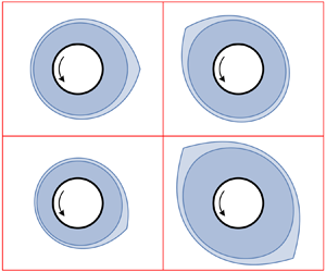
  $Q$ shown in figure 2 do not correspond to streamlines of the critical solution. This is confirmed by figure 3, which shows plots of typical streamlines $\psi = \text {constant}$, where $\psi$ is given by (3.7), for a critical and a subcritical solution. In particular, figure 3(a) shows that all of the streamlines of the critical solution (except, of course, for the substrate $y = 0$), and not just the critical free surface $y = h_{c}$, have a corner at the same position $\theta = \theta _{c}$.

Figure 3. Plots of typical streamlines  $\psi = \text {constant}$, where $\psi$ is given by (3.7), for (a) the critical solution with $Q = Q_{c} \simeq 0.403$ and (b) the subcritical solution with $Q = 9Q_{c}/10 \simeq 0.363\ (< Q_{c})$, when $F = 1$ and $K = 0$.
5. Properties of the full-film solutions
In this section we describe some of the properties of the full-film solutions obtained in § 4. Then in §§ 6 and 7 we describe the behaviour of the solutions in the special case when the airflow has no circulation ( $K = 0$) and in the general case when the airflow has non-zero circulation ( $K \ne 0$), respectively, and finally in § 8 we consider the mass of fluid on the cylinder.
5.1. General properties
In this subsection we describe some of the general properties of the full-film solutions.
At any fixed position  $\theta$, differentiating (3.8) with respect to $Q$ gives $(1 - h^2 f)(\partial h/\partial Q)= 1$, and, since it can be shown from (3.8) that for full-film solutions it is necessary that $h^2 f \le 1$, we deduce immediately that $\partial h/\partial Q > 0$, and hence that $h$ increases monotonically with $Q$.
$Q$.
On the other hand, for any fixed value of  $Q$, differentiating (3.8) with respect to $\theta$ gives $(1 - h^2 f)h' = h^3 f'/3$, showing that $h'$ has the same sign as $f'$ everywhere, and hence that the positions of the stationary points of $h$ are determined by the equation $f' = 0$, which may be written in the form
 \begin{equation} 8F^2\sin^2\theta - (1 + 2FK) \sin\theta - 4F^2 = 0, \end{equation}
whose solutions for  $\theta$ satisfy
 \begin{equation} \sin\theta = \frac{1 + 2FK \pm [(1 + 2FK)^2 + 128F^4]^{1/2}}{16F^2}. \end{equation}
As these solutions are independent of  $Q$, the stationary points of $h$ occur at the same positions $\theta$ for all values of $Q$. Moreover, at all of the stationary points of $h$ we have $3(1 - h^2 f)h'' = h^3 f''$ and $f'' = \pm [(1 + 2FK)^2 + 128F^4]^{1/2}\cos \theta$, which, taken together, show that the nature of each stationary point is given by the sign of $\pm \cos \theta$ there. In classical coating flow, $h$ has two stationary points, namely a maximum at $\theta = 0$ (i.e. on the right-hand side of the cylinder) and a minimum at $\theta = {\rm \pi}$ (i.e. on the left-hand side of the cylinder); however, the presence of the airflow can result in qualitatively different behaviour of the fluid film. In particular, as will be described subsequently, in the present problem $h$ can have as many as four stationary points. Moreover, as mentioned in § 1, in classical coating flow $h$ has top-to-bottom (but not right-to-left) symmetry; however, the presence of the non-uniform pressure due to the airflow means that, in general, in the present problem $h$ does not have top-to-bottom symmetry.
It is immediately apparent from (3.6)–(3.8) that at any zero of  $f$ the film has thickness $h = Q$, and that the fluid there moves locally with uniform velocity $u \equiv 1$ (i.e. as a plug). Moreover, the fact that $Q = h > 0$ for such values of $\theta$ means that the constant flux $Q$ is always positive, i.e. for full-film solutions the flux is always everywhere in the same direction as the rotation of the cylinder (i.e. anticlockwise). In fact, by using (3.6) to show that $u \ge 1$ when $f < 0$ and $1/2 \le u \le 1$ when $f > 0$, we can obtain the stronger result that, since the airflow does not exert a shear stress on the free surface of the film, the azimuthal velocity of the film $u$ (and not just the flux $Q$) is always positive, i.e. the azimuthal velocity of the film is always everywhere in the same direction as the rotation of the cylinder. This behaviour is in contrast to that of the corresponding problem of coating flow in the presence of a uniform shear stress on the free surface of the film, in which a sufficiently strong shear stress that acts in opposition to the rotation of the cylinder can cause not only the azimuthal velocity of the film $u$ closest to the free surface, but possibly also the flux $Q$, to become negative.
5.2. Critical solutions
In this subsection we describe the behaviour of the critical full-film solutions, i.e. solutions for which the flux and mass of fluid take the critical values  $Q = Q_{c}$ and $M = M_{c}$, respectively, above which no full-film solution exists, so that $M_{c}$ is the maximum mass of fluid that can be supported on the cylinder for given values of $F$ and $K$. As mentioned in § 4, all of the streamlines of the critical solution (except for the substrate $y=0$), and, in particular, the critical free surface $y = h_{c}$, have a corner at $\theta = \theta _{c}$.
As in classical coating flow, the critical solution corresponds to a saddle of the function  $Q$ given by (3.8), at which $Q$ satisfies the criticality conditions
 \begin{equation} \frac{\partial Q}{\partial h} = 0,\quad \frac{\partial Q}{\partial \theta} = 0, \end{equation}
leading to
 \begin{equation} h^2 f = 1,\quad f' = 0, \end{equation}
and any saddle of  $Q$ corresponds to a corner in the critical free surface $y = h_{c}$. It can be shown that the function $Q$ has no maximum or minimum stationary points, and, depending on the values of $F$ and $K$, has either one or two saddle points; in the latter case it is the saddle associated with the smaller value of $Q$ (and hence the smaller value of $M$) that corresponds to the critical solution.
The first of the criticality conditions (5.4a) gives the thickness of the critical film at the corner, namely
 \begin{equation} h_{c}(\theta_{c}) = \frac{1}{f(\theta_{c})^{1/2}}\end{equation}
(which, in particular, shows that a corner may occur only where  $f(\theta _{c}) > 0$), while the second of the criticality conditions (5.4b) shows that solutions for $\theta _{c}$ satisfy (5.2).
Figure 4 shows plots of the critical film thickness  $h_{c}$ when $K = 0$ as a function of $\theta /{\rm \pi}$ for a range of values of $F$. As figure 4 illustrates, the global maximum thickness of the critical film (and hence the maximum possible thickness of any film for given values of $F$ and $K$) always occurs at the corner, and expanding (3.8) about $\theta = \theta _{c}$ shows that near the corner the critical free surface $y = h_{c}$ has the local form
 \begin{equation} h_{c} = h_{c}(\theta_{c}) + h_1 \vert\theta - \theta_{c}\vert + O(\theta - \theta_{c})^2, \end{equation}
where
 \begin{equation} h_1 ={-}\frac{h_{c}^2[{-}f''(\theta_{c})]^{1/2}}{\sqrt{6}}\quad (< 0). \end{equation}
Figure 4. Plots of the critical film thickness  $h_{c}$ when $K = 0$ as a function of $\theta /{\rm \pi}$ for $F = 0$, $1/4$, $1/2$, …, $3$.
$3$.
Evaluating (3.8) at  $\theta =\theta _{c}$ gives the critical flux,
 \begin{equation} Q_{c} = \frac{2h_{c}(\theta_{c})}{3} = \frac{2}{3f(\theta_{c})^{1/2}}, \end{equation}
and (3.9) gives the critical mass,
 \begin{equation} M_{c} = \int_{-{\rm \pi}}^{\rm \pi} h_{c}(\theta) \, \textrm{d} \theta. \end{equation}
 Note that critical free surfaces with two corners may also occur, but only at leading order in the limit of a fast far-field airflow,  $F \to \infty$, and in the special case $FK = -1/2$; these exceptional situations will be described in §§ 6 and 7, respectively.
5.3. Subcritical solutions
In this subsection we describe the behaviour of the subcritical full-film solutions, i.e. solutions for which the flux  $Q$ and mass $M$ of fluid satisfy $0 < Q < Q_{c}$ and $0 < M < M_{c}$. As mentioned in § 4, unlike for the critical solutions described in § 5.2, all of the streamlines of the subcritical solutions, and, in particular, the subcritical free surface $y = h$, are smooth. However, as described in § 5.1, the global maximum of the subcritical film thickness still always occurs at $\theta = \theta _{c}$ (i.e. at the same position as the corner in the critical free surface $y = h_{c}$), and expanding (3.8) about $\theta = \theta _{c}$ shows that near the maximum the subcritical free surface $y = h$ has the locally parabolic form
 \begin{equation} h = h_0 + \frac{h_0^3 f''(\theta_{c})}{6[1 - h_0^2 f(\theta_{c})]} (\theta - \theta_{c})^2 + O(\theta - \theta_{c})^3, \end{equation}
where  $h_0 = h(\theta _{c})$ ( $0 < h_0 < h_{c}(\theta _{c})$) is the value of $h$ at $\theta = \theta _{c}$ obtained from (3.8).
In the limit of small flux,  $Q \to 0$, the subcritical film thickness $h$ is given by
 \begin{equation} h = Q + \frac{f}{3}Q^3 + O(Q^5), \end{equation}
and hence from (3.9) the mass  $M$ is given by
 \begin{equation} M = 2{\rm \pi} Q + \frac{\rm \pi}{3}[(1+2FK)^2 + 4F^4]Q^5 + O(Q^9). \end{equation}
Eliminating  $Q$ between (5.11) and (5.12) we obtain the expression for $h$ in the limit of small mass, $M \to 0$, namely
 \begin{equation} h = \frac{M}{2{\rm \pi}} + \frac{f}{24{\rm \pi}^3}M^3 + O(M^5), \end{equation}
showing that the film is very thin with uniform thickness  $M/(2{\rm \pi}) \ll 1$ at leading order in this limit.
6. Solutions when the airflow has no circulation ( $K = 0$)

In this section we use the results obtained thus far to describe the behaviour of the full-film solutions when the airflow has no circulation, corresponding to  $K = 0$.
In this case the pressure gradient within the film is entirely due to the far-field airflow, and the flux it induces, namely  $(2F^2h^3/3)\sin {2\theta }$, drives flow away from the left-hand and right-hand sides of the cylinder and towards the top and bottom of the cylinder (i.e. away from $\theta =0$ and $\theta ={\rm \pi}$ and towards $\theta ={\rm \pi} /2$ and $\theta =-{\rm \pi} /2$). The behaviour of the film is therefore a consequence of the competition between this flux and those due to the rotation of the cylinder and gravity, which, as in classical coating flow, drive flow in the same direction as the rotation of the cylinder (i.e. anticlockwise) and away from the top and towards the bottom of the cylinder (i.e. away from $\theta ={\rm \pi} /2$ and towards $\theta =-{\rm \pi} /2$), respectively.
As described in § 5.1, the positions of the stationary points of  $h$ are given by (5.2), which reduces to
 \begin{equation} \sin\theta = \frac{1\pm{(1 + 128F^4)^{1/2}}}{16F^2} \end{equation}
when  $K = 0$, and the nature of each stationary point is given by the sign of $\pm \cos \theta$. We denote the solutions of (6.1) in the interval $-{\rm \pi} /2 \le \theta \le {\rm \pi}/2$ by $\theta =\theta _{+}$ ( ${\rm \pi} /4 \le \theta _{+} \le {\rm \pi}/2$) and $\theta =\theta _{-}$ ( $-{\rm \pi} /4 \le \theta _{-} \le 0$), respectively, where the subscript $\pm$ corresponds to the $\pm$ in (6.1), and in terms of which the solutions of (6.1) are given by $\theta = \theta _{+}$ and $\theta = {\rm \pi}-\theta _{+}$ for $F \ge 1/2$ and $\theta = \theta _{-}$ and $\theta = -{\rm \pi} -\theta _{-}$ for $F \ge 0$.
Figure 5 shows a plot of the scaled positions  $\theta /{\rm \pi}$ of the stationary points of $h$ when $K = 0$ given by (6.1) as functions of $F$. The positions corresponding to a local maximum and a local minimum of $h$ are plotted with solid lines and dashed lines, respectively. In particular, figure 5 shows that when $K = 0$ the film thickness $h$ has two stationary points when $0 \le F < 1/2$, three stationary points when $F = 1/2$, and four stationary points when $F > 1/2$, and that the positions of these stationary points on the cylinder are symmetrical about the vertical line $\theta = \pm {\rm \pi}/2$.

Figure 5. Plot of the scaled positions  $\theta /{\rm \pi}$ of the stationary points of $h$ when $K = 0$ given by (6.1) as functions of $F$. The positions corresponding to a local maximum and a local minimum of $h$ are plotted with solid lines and dashed lines, respectively.
The plots of the film thickness  $h$ for a range of values of $Q$ and $F$ shown in figure 2 illustrate the qualitative changes in the behaviour of $h$ as the speed of the far-field airflow is increased from zero (i.e. as $F$ is increased from zero).
As mentioned in § 5.1, in classical coating flow  $h$ has a maximum at $\theta = \theta _{-} = 0$ and a minimum at $\theta = -{\rm \pi} -\theta _{-} = -{\rm \pi}$ (i.e. at $\theta = {\rm \pi}$, see figure 2a). Figure 5 shows that as $F$ is increased from zero this maximum and minimum of $h$ move towards the bottom of the cylinder, approaching $\theta = -{\rm \pi} /4$ and $\theta = -3{\rm \pi} /4$, respectively, in the limit of a fast far-field airflow, $F \to \infty$. Figure 5 also shows that when $F = 1/2$ a second maximum and minimum of $h$ appear (initially as a stationary point of inflection) at the top of the cylinder (i.e. at $\theta = {\rm \pi}/2$, see figure 2c), and thereafter that as $F$ is increased from $1/2$ this second maximum and minimum move away from the top of the cylinder, approaching $\theta = {\rm \pi}/4$ and $\theta = 3{\rm \pi} /4$, respectively, in the limit of a fast far-field airflow, $F \to \infty$. Moreover, as figures 2–4 illustrate, when $K = 0$ the largest maximum and the smallest minimum of $h$ are always located on the lower half of the cylinder. In particular, except in the exceptional situation mentioned in § 5.2 in which it has two corners, the corner in the critical free surface $y = h_{c}$ always occurs at $\theta = \theta _{c} = \theta _{-}$.
From (5.5) and (6.1) the thickness of the critical film at the corner (i.e. the maximum possible thickness of any film for a given value of  $F$) is given explicitly in terms of $F$ by
 \begin{equation} h_{c}(\theta_{c})= \left(\frac{32\left[1 + (1 + 128F^4)^{1/2}\right]} {\left[3 + (1 + 128F^4)^{1/2}\right]^3}\right)^{1/4}, \end{equation}
and hence from (5.8) the critical flux is given explicitly in terms of  $F$ by
 \begin{equation} Q_{c}= \left(\frac{512\left[1 + (1 + 128F^4)^{1/2}\right]} {81\left[3 + (1 + 128F^4)^{1/2}\right]^3}\right)^{1/4}. \end{equation}
Figure 6 shows a plot of  $h_{c}(\theta _{c})$ given by (6.2) as a function of $F$. In particular, figure 6 shows that $h_{c}(\theta _{c})$ is a monotonically decreasing function of $F$ satisfying
 \begin{equation} h_{c}(\theta_{c}) = 1 - 4F^4 + O(F^8) \to 1^- \quad\mbox{as}\ F \to 0^+ \end{equation}
and
 \begin{equation} h_{c}(\theta_{c}) \sim \frac{1}{\sqrt{2}F} \to 0^+ \quad\mbox{as}\ F \to \infty. \end{equation}
Figure 6. Plot of the thickness of the critical film at the corner,  $h_{c}(\theta _{c})$, when $K = 0$ given by (6.2) as a function of $F$. The asymptotic behaviours of $h_{c}(\theta _{c})$ in the limits $F \to 0^+$ given by (6.4) and $F \to \infty$ given by (6.5) are plotted with dashed and dotted lines, respectively.
At leading order in the limit of a fast far-field airflow,  $F \to \infty$, the behaviour of the film is due only to the rotation of the cylinder and the far-field airflow. In this limit the film is very thin, $h = O(1/F) \ll 1$, and both the flux $Q = O(1/F) \ll 1$ and the mass $M = O(1/F) \ll 1$ are correspondingly very small. Thus if we write the leading-order solution as $h(\theta ) = \hat {h}(\theta )/F$, $Q = \hat {Q}/F$ and $M = \hat {M}/F$, where hatted quantities are $O(1)$ in the limit $F \to \infty$, then the rescaled film thickness $\hat {h}$ has the form of the solution for $h$ given in (4.1) with $f = -2\sin 2\theta$, while from (3.8) and (3.9) the rescaled flux $\hat {Q}$ and the rescaled mass $\hat {M}$ are given by
 \begin{equation} \hat{Q} = \hat{h} + \frac{2\hat{h}^3}{3}\sin2\theta\quad \text{and} \quad \hat{M} = \int_{-{\rm \pi}}^{\rm \pi} \hat{h}(\theta) \, \textrm{d} \theta, \end{equation}
respectively. Figure 7 shows plots of contours of  $\hat {Q}$ for $0 \le \hat {Q} \le \hat {Q}_{c}$, with each contour therefore representing the rescaled film thickness $\hat {h}$ for the corresponding value of $\hat {Q}$. As figure 7 shows, the rescaled film thickness $\hat {h}$ has period ${\rm \pi}$, with two identical maxima at $\theta = 3{\rm \pi} /4$ and $\theta = -{\rm \pi} /4$, and two identical minima at $\theta = {\rm \pi}/4$ and $\theta = -3{\rm \pi} /4$. In particular, as mentioned in § 5.2, the rescaled critical free surface $y = \hat {h}_{c}(\theta )$ corresponding to $\hat {Q} = \hat {Q}_{c} = \sqrt {2}/3 \simeq 0.471$ and $\hat {M} = \hat {M}_{c} \simeq 3.141$ has two identical corners at $\theta = \theta _{c} = 3{\rm \pi} /4$ and $\theta = \theta _{c} = -{\rm \pi} /4$ at both of which $\hat {h}_{c}(\theta _{c}) = 1/\sqrt {2} \simeq 0.707$.

Figure 7. Plots of contours of  $\hat {Q}$ for $0 \le \hat {Q} \le \hat {Q}_{c} = \sqrt {2}/3 \simeq 0.471$, with each contour therefore representing the rescaled film thickness $\hat {h}$ for the corresponding value of $\hat {Q}$. The contour interval is $\hat {Q}_{c}/10$.
7. Solutions when the airflow has non-zero circulation ($K \ne 0$)

In this section we use the results obtained thus far to describe the behaviour of the full-film solutions when the airflow has non-zero circulation, corresponding to  $K \ne 0$.
In this case, in addition to the pressure gradient due to the far-field airflow described in § 6, the pressure gradient within the film has an additional contribution due to the circulation of the airflow in combination with the far-field airflow, and the additional flux it induces, namely  $-(2FKh^3/3)\cos \theta$, either cooperates (when $K > 0$) or competes (when $K < 0$) with the flux due to gravity by driving flow either away from the top and towards the bottom of the cylinder (i.e. away from $\theta ={\rm \pi} /2$ and towards $\theta =-{\rm \pi} /2$) when $K > 0$ or vice versa when $K < 0$. As might have been anticipated, the presence of non-zero circulation leads to somewhat more complicated behaviour of the film than that in the absence of circulation described in § 6. When $K \ne 0$ it is convenient to introduce the parameter $\beta$ defined by
 \begin{equation} \beta = \frac{1 + 2FK}{4F^2}. \end{equation}
 As described in § 5.1, the positions of the stationary points of  $h$ are given by (5.2), which, in terms of the parameter $\beta$ defined by (7.1), takes the form
 \begin{equation} \sin\theta = \frac{\beta \pm (\beta^2 + 8)^{1/2}}{4}, \end{equation}
and the nature of each stationary point is again given by the sign of  $\pm \cos \theta$. As for (6.1) in § 6, we denote the solutions of (7.2) in the interval $-{\rm \pi} /2 \le \theta \le {\rm \pi}/2$ by $\theta =\theta _{+}$ ( $0 \le \theta _{+} \le {\rm \pi}/2$) and $\theta =\theta _{-}$ ( $-{\rm \pi} /2 \le \theta _{-} \le 0$), respectively, where the subscript $\pm$ corresponds to the $\pm$ in (7.2), and in terms of which the solutions of (7.2) are given by $\theta = \theta _{+}$ and $\theta = {\rm \pi}-\theta _{+}$ for $\beta \le 1$ and $\theta = \theta _{-}$ and $\theta = -{\rm \pi} -\theta _{-}$ for $\beta \ge -1$.
Figure 8 shows a plot of the scaled positions  $\theta /{\rm \pi}$ of the stationary points of $h$ given by (7.2) plotted as functions of $F$ for a range of values of $K$ (including the case $K = 0$ shown in figure 5). The positions corresponding to a local maximum and a local minimum of $h$ are again plotted with solid lines and dashed lines, respectively. In particular, figure 8 shows that the film thickness $h$ has two stationary points when $K < K_1$ and when $K > K_3$, three stationary points when $K = K_1$ and when $K = K_3$, and four stationary points when $K_1 < K < K_3$, where the critical values $K = K_1$, $K = K_2 = (K_1+K_3)/2$ and $K = K_3$, corresponding to $\beta = -1$, $\beta = 0$ and $\beta = 1$, respectively, and satisfying $K_1 < K_2 < 0$ and $K_3 > K_2$, are defined by
 \begin{equation} K_1 ={-}2F-\frac{1}{2F},\quad K_2 ={-}\frac{1}{2F}\quad \text{and} \quad K_3 = 2F-\frac{1}{2F}, \end{equation}
and the positions of these stationary points on the cylinder are again symmetrical about the vertical line  $\theta = \pm {\rm \pi}/2$.

Figure 8. Plot of the scaled positions  $\theta /{\rm \pi}$ of the stationary points of $h$ given by (7.2) as functions of $F$ for $K = -5$, $-4$, …, $3$. The positions corresponding to a local maximum and a local minimum of $h$ are plotted with solid lines and dashed lines, respectively.
Figure 9 shows plots of contours of  $Q$ for $0 \le Q \le Q_{c}$, with each contour therefore representing the film thickness $h$ for the corresponding value of $Q$, for a range of values of $F$ and $K$. The plots shown in figure 9 illustrate the qualitative changes in the behaviour of $h$ as the speed of the far-field airflow and the circulation are varied (i.e. as $F$ and $K$ are varied).

Figure 9. Plots of contours of  $Q$ for $0 \le Q \le Q_{c}$, with each contour therefore representing the film thickness $h$ for the corresponding value of $Q$, for (a) $F = 1/2$ and $K = -3$ ( $\theta _{c} = 0.881{\rm \pi}$, $Q_{c} \simeq 0.449$), (b) $F = 1$ and $K = -5/2$ ( $\theta _{c} = 0.833{\rm \pi}$, $Q_{c} \simeq 0.292$), (c) $F = 3/2$ and $K = -3/2$ ( $\theta _{c} = 0.789{\rm \pi}$, $Q_{c} \simeq 0.250$), (d) $F = 1$ and $K = -1/2$ ( $\theta _{c} = 3{\rm \pi} /4$ and $-{\rm \pi} /4$, $Q_{c} \simeq 0.471$), (e) $F = 3/2$ and $K = 5/6$ ( $\theta _{c} = -0.211{\rm \pi}$, $Q_{c} \simeq 0.250$), (f) $F = 1$ and $K = 3/2$ ( $\theta _{c} = -{\rm \pi} /6$, $Q_{c} \simeq 0.292$) and (g) $F = 1/2$ and $K = 1$ ( $\theta _{c} = -0.119{\rm \pi}$, $Q_{c} \simeq 0.449$). In each case the contour interval is $Q_{c}/10$.
The qualitative changes in the behaviour of the film thickness  $h$ as $F$ and $K$ are varied are summarised in figure 10, which represents one of the key results of the present work. Specifically, figure 10 is a plot of the $F$–
$F$– $K$ parameter plane showing how the three curves $K = K_1$, $K = K_2$ and $K = K_3$ given by (7.3a–c) divide the plane into the four regions $K < K_1$, $K_1 < K < K_2$, $K_2 < K < K_3$ and $K > K_3$ in which the behaviour of the film thickness $h$ (typical examples of which are sketched in the insets) is qualitatively different. In addition, the asymptotes of $K = K_1$ and $K = K_3$ as $F \to \infty$, namely $K = \mp 2F$, are plotted with dashed lines. Note that these two straight lines correspond to $\kappa /(4{\rm \pi} aU_\infty ) = K/(2F) = \mp 1$ and so, as described in § 3, they also separate the $F$–
$F$– $K$ parameter plane into the three regions $K < -2F$, $-2F < K < 2F$ and $K > 2F$ in which the stagnation points of the airflow are directly below the cylinder, on the cylinder and directly above the cylinder, respectively. In particular, as figure 10 shows, in the limit of a fast far-field airflow, $F \to \infty$, but not otherwise, a second local maximum and minimum in the film thickness occur if and only if the stagnation points of the airflow are on the cylinder. Moreover, as figure 9 illustrates, when $K < K_2$ the largest maximum and the smallest minimum of $h$ always occur on the upper half of the cylinder, and the corner in the critical free surface always occurs at $\theta = \theta _{c} = {\rm \pi}-\theta _{+}$, but when $K > K_2$ the largest maximum and the smallest minimum of $h$ always occur on the lower half of the cylinder, and the corner in the critical free surface always occurs at $\theta = \theta _{c} = \theta _{-}$.

Figure 10. Plot of the  $F$–
$F$– $K$ parameter plane showing how the three curves $K = K_1$, $K = K_2$ and $K = K_3$ given by (7.3a–c) divide the plane into the four regions $K < K_1$, $K_1 < K < K_2$, $K_2 < K < K_3$ and $K > K_3$ in which the behaviour of the film thickness $h$ (typical examples of which are sketched in the insets) is qualitatively different. In addition, the asymptotes of $K = K_1$ and $K = K_3$ as $F \to \infty$, namely $K = \mp 2F$, are plotted with dotted lines.
From (5.5) and (7.2) the thickness of the critical film at the corner (i.e. the maximum possible thickness of any film for given values of  $F$ and $K$) is given explicitly in terms of $F$ and $\beta$ by
 \begin{equation} h_{c}(\theta_{c}) = \frac{1}{F} \left(\frac{2}{8 + 20\beta^2 - \beta^4 + \vert\beta\vert(\beta^2 + 8)^{3/2}}\right)^{1/4}, \end{equation}
and hence from (5.8) the critical flux is given explicitly in terms of  $F$ and $\beta$ by
 \begin{equation} Q_{c} = \frac{2}{3F} \left(\frac{2}{8 + 20\beta^2 - \beta^4 + \vert\beta\vert(\beta^2 + 8)^{3/2}}\right)^{1/4}. \end{equation}
Note that  $\theta _{\pm }$, $\theta _{c}$, $Fh_{c}(\theta _{c})$ and $FQ_{c}$ depend on $F$ and $K$ only via $\beta$, and that $Fh_{c}(\theta _{c})$ and $FQ_{c}$ are even functions of $\beta$. Figure 11 shows a plot of $Fh_{c}(\theta _{c})$ given by (7.4) as a function of $\beta$. In particular, figure 11 shows that $Fh_{c}(\theta _{c})$ is a monotonically decreasing function of $\vert \beta \vert$ satisfying
 \begin{equation} Fh_{c}(\theta_{c}) = \frac{1}{\sqrt{2}} - \frac{1}{2}\vert\beta\vert + O(\beta^2) \to {\frac{1}{\sqrt{2}}}^{-}\quad \text{as}\ \beta \to 0\end{equation}
and
 \begin{equation} Fh_{c}(\theta_{c}) \sim \frac{1}{2\sqrt{\vert\beta\vert}}\to 0^+ \quad \text{as}\ \beta \to \pm \infty. \end{equation}
Figure 11. Plot of the scaled thickness of the critical film at the corner,  $Fh_{c}(\theta _{c})$, given by (7.4) as a function of $\beta$. The asymptotic behaviours of $Fh_{c}(\theta _{c})$ in the limits $\beta \to 0^+$ given by (7.6) and $\beta \to \pm \infty$ given by (7.7) are plotted with dashed and dotted lines, respectively.
As mentioned in § 3, in the special case  $FK = -1/2$, corresponding to $K = K_2$ (i.e. $\beta = 0$), the behaviour of the film is due only to the rotation of the cylinder and the far-field airflow. Clearly this situation is closely analogous to that at leading order in the limit of a fast far-field airflow, $F \to \infty$, when $K = 0$ described in § 6. The parameter $F$ (which may now take any positive value) may again be scaled out of the problem by writing the solution as $h(\theta ) = \hat {h}(\theta )/F$, $Q = \hat {Q}/F$ and $M = \hat {M}/F$, where the solutions for $\hat {h}(\theta )$, $\hat {Q}$ and $\hat {M}$ are given in § 6. In particular, the film thickness $h$ has period ${\rm \pi}$, with two identical maxima at $\theta = 3{\rm \pi} /4$ and $\theta = -{\rm \pi} /4$, and two identical minima at $\theta = {\rm \pi}/4$ and $\theta = -3{\rm \pi} /4$, and the critical free surface $y = h_{c}(\theta )$ has two identical corners at $\theta = \theta _{c} =3{\rm \pi} /4$ and $\theta = \theta _{c} = -{\rm \pi} /4$ (see, e.g. figure 9d).
At leading order in the limit of a strong circulation,  $K \to \pm \infty$, the behaviour of the film is due only to the rotation of the cylinder and the circulation of the airflow. In this limit the film is very thin, $h = O(\vert K \vert ^{-1/2}) \ll 1$, and both the flux $Q = O(\vert K \vert ^{-1/2}) \ll 1$ and the mass $M = O(\vert K \vert ^{-1/2}) \ll 1$ are correspondingly very small. Thus if we write the leading-order solution as $h(\theta ) = \bar {h}(\theta )/(2F\vert K \vert )^{1/2}$, $Q = \bar {Q}/(2F\vert K \vert )^{1/2}$ and $M = \bar {M}/(2F\vert K \vert )^{1/2}$, where barred quantities are $O(1)$ in the limit $K \to \pm \infty$, then the rescaled film thickness $\bar {h}$ has the form of the solution for $h$ given in (4.1) with $f = \pm \cos \theta$, while from (3.8) and (3.9) the rescaled flux $\bar {Q}$ and the rescaled mass $\bar {M}$ are given by
 \begin{equation} \bar{Q} = \bar{h} \mp \frac{\bar{h}^3}{3}\cos\theta\quad \text{and} \quad \bar{M} = \int_{-{\rm \pi}}^{\rm \pi} \bar{h}(\theta) \, \textrm{d} \theta, \end{equation}
respectively. Thus  $\bar {h}(\theta )$, $\bar {Q}$ and $\bar {M}$ are the solutions of the classical coating-flow problem when $K \to \infty$, and the solutions of the mirror image of the classical coating-flow problem in the vertical line $\theta = \pm {\rm \pi}/2$ (i.e. the solutions of the classical coating-flow problem with the direction of the rotation of the cylinder reversed) when $K \to -\infty$. In particular, the rescaled film thickness $\bar {h}$ has a local maximum at $\theta = 0$ and a local minimum at $\theta = {\rm \pi}$, and the rescaled critical free surface $y = \bar {h}_{c}(\theta )$ corresponding to $\bar {Q} = \bar {Q}_{c} = 2/3$ and $\bar {M} = \bar {M}_{c} \simeq 4.443$ has a corner at $\theta = \theta _{c} = 0$ at which $\bar {h}_{c}(\theta _{c}) = 1$ when $K \to \infty$, and the mirror image of this behaviour when $K \to -\infty$.
8. The mass of fluid on the cylinder
Figure 12(a) shows a plot of the mass  $M$ of fluid on the cylinder when $K = 0$ given by (3.9) as a function of $Q$ for $0 \le Q \le Q_{c}$ for a range of values of $F$, showing that $M$ increases monotonically (almost linearly) with $Q$. Since, as figure 12(a) shows, $M$ depends only rather weakly on $F$, figure 12(b) shows a plot of the difference $M-M_0$ between $M$ when $K = 0$ and the mass of fluid in the absence of an airflow (i.e. in the corresponding classical coating-flow problem), denoted by $M_0$, also as a function of $Q$ for $0 < Q \le Q_{c}$ for a range of values of $F$. In both parts of figure 12, the dots denote the values of the critical mass $M = M_{c}$ at the critical flux $Q=Q_{c}$ above which there is no full-film solution. In particular, note that the asymptotic solution for $M$ in the limit $Q \to 0$ given in (5.12) provides excellent approximations to both $M$ and $M-M_0$, namely
 \begin{equation} M \sim 2{\rm \pi} Q \quad \hbox{and} \quad M-M_0 \sim \frac{4{\rm \pi}}{3}[(1+2FK)^2 + 4F^4 - 1]Q^5, \end{equation}
over the entire range of values of  $Q$ (i.e. for $0 \le Q \le Q_{c}$).

Figure 12. (a) Plot of the mass  $M$ of fluid on the cylinder when $K = 0$ given by (3.9) as a function of $Q$ for $0 \le Q \le Q_{c}$ for $F = 0$, $1/2$, $1$,
$1$,  $3/2$, $2$. (b) Plot of the difference $M-M_0$ between $M$ when $K = 0$ and the mass of fluid in the absence of an airflow, $M_0$, as a function of $Q$ for $0 \le Q \le Q_{c}$ for $F = 0$, $1/4$, $1/2, \ldots, 3$. In both panels, the dots denote the values of $M = M_{c}$ at $Q=Q_{c}$ above which there is no full-film solution.
Figures 13 and 14 show plots of the critical mass of fluid on the cylinder,  $M_{c}$, given by (5.9) as a function of $F$ for a range of values of $K$ and as a function of $K$ for a range of values of $F$, respectively. Figures 13 and 14 show that when $K \ge 0$, $M_{c}$ decreases monotonically towards zero with $F$ and $K$ (i.e. the maximum mass of fluid that can be supported on the cylinder is always less than that in classical coating flow), but that when $K < 0$, $M_{c}$ attains the value $M_{c} \simeq 3.141/F \simeq 6.282(-K)$ when $FK = -1/2$ (i.e. the maximum mass of fluid that can be supported on the cylinder can be greater than that in classical coating flow).

Figure 13. Plot of the critical mass of fluid on the cylinder,  $M_{c}$, given by (5.9) as a function of $F$ for (a) $K = 0$, $5$,
$5$,  $10$ and (b) $K = -5$, $-4$, …, $-1$.
$-1$.

Figure 14. Plot of the critical mass of fluid on the cylinder,  $M_{c}$, given by (5.9) as a function of $K$ for $F = 1/10$, $1/5, \ldots, 3/5$.
9. Stability
The stability of the steady two-dimensional full-film solutions obtained in the present work to both two-dimensional and three-dimensional (i.e. axial) disturbances is of considerable interest. For leading-order classical rimming flow, and hence, since the governing equations for the leading-order film thickness in the two problems are identical, for leading-order classical coating flow, O'Brien (Reference O'Brien2002a) showed that subcritical two-dimensional full-film solutions are neutrally stable to two-dimensional disturbances, and a number of other authors (including Hosoi & Mahadevan Reference Hosoi and Mahadevan1999; O'Brien Reference O'Brien2002b; Jin & Acrivos Reference Jin and Acrivos2004; Benilov & O'Brien Reference Benilov and O'Brien2005; Noakes, King & Riley Reference Noakes, King and Riley2006; Pougatch & Frigaard Reference Pougatch and Frigaard2011; Benilov & Lapin Reference Benilov and Lapin2013) have investigated the stability of coating and/or rimming flow in the presence of additional physical effects and/or to three-dimensional disturbances.
Particularly relevant to the present work is the recent study by Newell & Viljoen (Reference Newell and Viljoen2019), who sought to extend the pioneering work of Hinch & Kelmanson (Reference Hinch and Kelmanson2003) on the long-time dynamics of two-dimensional coating flow to investigate the effect of the same airflow as that considered in the present work. However, unlike in the present work, Newell & Viljoen (Reference Newell and Viljoen2019) also included surface-tension effects, characterised by a constant coefficient of surface tension  $\sigma$. Unfortunately, as we shall now show, their analysis needs to be revisited. Substituting their equation (2) into their equation (3) recovers the present expression for $p_{a}$ given by (2.1) in the case $\kappa = 2{\rm \pi} a^2\varOmega$. However, their expression for $Q$ given by their equation (5) has the opposite sign for the term due to the pressure gradient within the film compared with the correct expression given by (3.2), while their expression for $p$ given by their equation (6) has the opposite sign for the term due to surface tension compared with the correct expression (see, e.g. Evans et al. Reference Evans, Schwartz and Roy2004). Eliminating $p$ between their equations (5) and (6) yields their expression for $Q$, namely
 \begin{align} Q = a \varOmega h - \frac{h^3}{3\mu a}\left[\rho ga\cos\theta - \frac{\sigma}{a^2}\frac{\partial}{\partial\theta}\left(\frac{\partial^2 h}{\partial\theta^2}+h\right) + 2\rho_{a}U_\infty\cos\theta\left(2U_\infty\sin\theta-a\varOmega\right)\right], \end{align}
which differs from the present expression for  $Q$ given by (3.3) in the case $\kappa = 2{\rm \pi} a^2\varOmega$ due to the presence of the term due to surface tension (i.e. the term involving $\sigma$) and the sign of the term due to the airflow (i.e. the term involving $\rho _{a}$). As a consequence of this sign error in $Q$, their equation (7) has the wrong sign of the term due to the airflow. Moreover, in the absence of the airflow their expression for the temporal decay rate of a small perturbation to a film of uniform thickness given by their equation (13) yields twice the corresponding expression obtained by Hinch & Kelmanson (Reference Hinch and Kelmanson2003) for the classical coating-flow problem, and so obtaining the correct description of the behaviour is evidently not simply a matter of reversing the sign of the term due to the airflow. Hence the long-time dynamics of coating flow in the presence of an airflow remains an open question.
A full stability analysis of the present solutions is outside the scope of the present work, but, as we shall now show, the analysis of O'Brien (Reference O'Brien2002a) can be generalised to show that the present subcritical full-film solutions are neutrally stable to two-dimensional disturbances. Non-dimensionalising time  $t$ with $\varOmega ^{-1}$, the non-dimensional evolution equation for the film thickness is
 \begin{equation} \frac{\partial h}{\partial t}+\frac{\partial Q}{\partial \theta}=0, \end{equation}
and so perturbing around any of the present steady full-film solutions with a small perturbation with growth rate  $s$ of the form $\phi (\theta )\exp (st)$ and linearising yields the equation
 \begin{equation}
(1-h^2f)\phi' + [s - (h^2 f)']\phi = 0, \end{equation}
\begin{equation}
(1-h^2f)\phi' + [s - (h^2 f)']\phi = 0, \end{equation}
with solution
 \begin{equation} \phi \propto \frac{1}{1-h^2f}\exp\left({-}s\int \frac{1}{1-h^2f} \, \textrm{d}{\theta}\right). \end{equation}
Since, as previously remarked, the present subcritical full-film solutions satisfy  $h^2f < 1$, the integrand in (9.4) is positive, and so, since $\phi$ must be $2{\rm \pi}$-periodic in $\theta$, we deduce that the growth rate $s$ must be purely imaginary, i.e. the present subcritical full-film solutions are neutrally stable to two-dimensional disturbances. This is, of course, only a rather limited result, but it at least provides a starting point for future work on the stability of coating flow in the presence of an airflow.
10. Conclusions
In the present work we undertook a detailed analysis of steady coating flow of a thin film of a viscous fluid on the outside of a uniformly rotating horizontal circular cylinder in the absence of surface-tension effects but in the presence of a non-uniform pressure distribution due to an irrotational airflow with circulation and showed that the presence of the airflow can result in qualitatively different behaviour of the fluid film from that in classical coating flow. This problem is not only of interest in its own right, but also as a paradigm for the wide range of practical situations in which a thin film of fluid on a moving solid substrate is subject to an airflow. We found that, as in classical coating flow, full-film solutions are possible only when the flux  $Q$ and mass $M$ of fluid do not exceed critical values $Q_{c}$ and $M_{c}$, which we determined in terms of the parameters $F$ and $K$ representing the speed of the far-field airflow and the circulation of the airflow, respectively. In particular, (6.3) and (7.5) are explicit expressions for $Q_{c}$ in the special case of no circulation $K = 0$ and in the general case of non-zero circulation $K \ne 0$, respectively. The qualitative changes in the behaviour of the film thickness as $F$ and $K$ are varied are summarised in figure 10 and illustrated in figure 15. Specifically, figure 10 shows how the three curves $K = K_1$, $K = K_2$ and $K = K_3$ given by (7.3a–c) divide the $F$–
$F$– $K$ parameter plane into the four regions $K < K_1$, $K_1 < K < K_2$, $K_2 < K < K_3$ and $K > K_3$ in which the behaviour of the film thickness is qualitatively different. In particular, the film thickness can have as many as four stationary points and, in general, has neither top-to-bottom nor right-to-left symmetry (in contrast to having two stationary points and top-to-bottom symmetry in classical coating flow). It should be noted that the behaviour summarised in figure 10 is qualitatively different from that in the corresponding problem of coating flow in the presence of a uniform shear stress on the free surface of the film, in which the film thickness only ever has two stationary points.

Figure 15. Examples of both critical and subcritical free surfaces on the rotating cylinder, for (a)  $F = 0$ and $K = 0$ (i.e. classical coating flow) ( $\theta _{c} = 0$, $Q_{c} = 2/3$), (b) $F = 1/2$ and $K = -7/5$ ( $\theta _{c} \simeq 0.790{\rm \pi}$, $Q_{c} \simeq 0.745$), (c) $F = 1/2$ and $K = 1/4$ ( $\theta _{c} \simeq -0.152{\rm \pi}$, $Q_{c} \simeq 0.541$) and (d) $F = 1/2$ and $K = -1$ ( $\theta _{c} = 3{\rm \pi} /4$ and $-{\rm \pi} /4$, $Q_{c} \simeq 0.943$), with $Q = Q_{c}$ and $Q = 0.85Q_{c}$ in each case. All of the panels are drawn on the same scale, but, for clarity the thicknesses of the fluid films are exaggerated.
When the circulation of the airflow is anticlockwise (i.e. in the same direction as the rotation of the cylinder) the maximum mass of fluid that can be supported on the cylinder is always less than that in classical coating flow, whereas when the circulation is in the opposite direction the maximum mass of fluid can be greater than that in classical coating flow. However, whatever the speed of the far-field airflow and the circulation of the airflow (i.e. whatever the values of  $F$ and $K$), the azimuthal velocity of the film is always in the same direction as the rotation of the cylinder.
Figure 15 shows examples of both critical and subcritical free surfaces on the rotating cylinder, including three examples with one corner in the critical free surface (figure 15a–c) and one example in the special case  $FK = -1/2$ with two corners in the critical free surface (figure 15d), and examples for which the critical flux $Q_{c}$ and the critical mass $M_{c}$ are larger (figure 15b,d) and smaller (figure 15c) than the critical flux $Q_{c} = 2/3$ and the critical mass $M_{c} = 4.443$ for classical coating flow (figure 15a).
In the present work we assumed that, since the film is thin, the airflow is unaffected by the presence of the film. In reality, this will not always be the case, and determining the influence of the shape of the film on the airflow remains an open problem. For example, the numerical studies of a thin rivulet of viscous fluid on a stationary cylinder in the presence of an airflow by Robertson et al. (Reference Robertson, Taylor, Wilson, Duffy and Sullivan2010) and Taylor & Robertson (Reference Taylor and Robertson2011, Reference Taylor and Robertson2015) suggest that there could be circumstances in which it is significant.
Acknowledgements
The first author (A.J.M.) gratefully acknowledges the financial support of the United Kingdom Engineering and Physical Sciences Research Council (EPSRC) via EPSRC Doctoral Training Partnership grant EP/S515632/1.
Declaration of interests
The authors report no conflict of interest.
Appendix A
In this appendix we provide the equations for the more general situation in which the far-field airflow, rather than being horizontal, is inclined at some prescribed angle  $\alpha$ (measured anti-clockwise from $\theta =0$) to the horizontal.
The air pressure on the free surface of the film,  $p_{a}=p_{a}(\theta )$, previously given by (2.1), becomes
 \begin{equation} p_{a} = p_\infty + \frac{\rho_{a}}{2}\left[U_\infty^2 - \left\{2U_\infty\sin(\theta - \alpha) - \frac{\kappa}{2{\rm \pi} a}\right\}^2\right], \end{equation}
and hence the volume flux,  $Q$, previously given by (3.3), becomes
 \begin{equation} Q = a \varOmega h - \frac{h^3}{3\mu a} \left[\rho ga\cos\theta - 2\rho_{a}U_\infty^2\sin{2(\theta - \alpha)} + \frac{\rho_{a}\kappa U_\infty}{{\rm \pi} a}\cos(\theta - \alpha)\right]. \end{equation}
 Non-dimensionalising and scaling according to (3.4), the pressure  $p=p_{a}$, previously given by (3.5), is now given by
 \begin{equation} p = p_{a} = \frac{1}{2}\left[F^2 - \{2F\sin(\theta-\alpha) - K\}^2\right], \end{equation}
while the azimuthal velocity, the streamfunction, the flux and the mass are again given by (3.6)–(3.9), respectively, where the function  $f = f(\theta )$, previously given by (3.10), is now given by
 \begin{equation} f(\theta) = \cos\theta + 2FK\cos(\theta-\alpha) - 2F^2\sin2(\theta-\alpha), \end{equation}
where  $F$ (
$F$ ( $\ge 0$) and $K$ are again defined by (3.11a,b). In particular, the equation for the positions of the stationary points of $h$, previously given by (5.1), is now given by
 \begin{equation} \sin\theta + 2FK\sin(\theta-\alpha) + 4F^2\cos{2(\theta-\alpha)}= 0. \end{equation}


 Open access