


1. Introduction
Detonation is a shock-induced extreme combustion phenomenon (Lee Reference Lee2008), which is seen as an ideal propulsion technology due to its supersonic propagation, nearly isovolumetric combustion and short combustion time. Consequently, detonation and detonation engines have been widely studied. Research on detonation has focused on investigation of the characteristics of the detonation wave itself, for example through theoretical solutions of the shock relations (Gordon & McBride Reference Gordon and McBride1976, Reference Gordon and McBride1994; Zhang et al. Reference Zhang, Wen, Zhang, Liu and Jiang2022b) and through descriptions of the morphology and standing region of the detonation wave (Teng & Jiang Reference Teng and Jiang2012) and the cellular structure of the detonation (Choi et al. Reference Choi, Kim, Jeung, Ma and Yang2007). Other research has focused on how to design new detonation engines. According to the type of detonation wave involved, these can be divided into rotating detonation engines (Gupta & Schwer Reference Gupta and Schwer2018), pulse detonation engines (Kailasanath Reference Kailasanath2011) and oblique detonation engines (ODEs) (He & Karagozian Reference He and Karagozian2003). Of these, ODEs have a good prospect for application because of their simpler structure. Therefore, it is important to investigate the structure of the detonation waves in the combustion chamber of an ODE. Unlike detonation waves that develop freely in open space, the oblique detonation waves (ODWs) that occur in the combustion chamber are inevitably subject to reflections. Different types of reflections can significantly affect the propulsive performance of an ODE. Zhang, Liu & Wen (Reference Zhang, Liu and Wen2022a) investigated the influence of the position at which reflection occurs on the type of reflection and revealed why Mach reflection does not occur in this case, as well as giving a formula for the stable position of the Mach stem. Wang et al. (Reference Wang, Zhang, Yang and Teng2020) investigated the structural changes that occur in the reflected wave system resulting from the reflection of an ODW by the upper wall of the combustion chamber and subject to the effect of an expansion nozzle in a simplified ODE model. Their results demonstrated that the thermal choking caused by the merger of subsonic zones has a significant effect on the stability of the reflected structure.
Given the close relationship between detonations and shocks, it is necessary to consider the reflection of shock waves before turning to the study of detonation waves. Mach (Reference Mach1878) reported the discovery of shock wave reflection in 1878 and recorded two different structures of shock wave reflection, namely regular reflection and Mach reflection. Von Neumann proposed a two-wave theory and a triple-wave theory, and on this basis established criteria for the transition between regular reflection and Mach reflection and for detachment (von Neumann Reference von Neumann1943, Reference von Neumann1945), thereby establishing a theoretical approach to the study of shock reflection. Since then, there have been many advances in the understanding of shock wave reflection, and its scope of application has been greatly enriched. Hornung & Robinson (Reference Hornung and Robinson1982) studied experimentally the dependence of the height of the Mach stem on the incident shock angle and gave an equation for the height of the stem. Subsequently, Ben-Dor (Reference Ben-Dor1992) proposed an approximate analytical model for the shape of the Mach stem with first-order accuracy and revealed the factors influencing the Mach stem height. The study of shock wave reflection is relevant to detonation wave reflection, since both involve an incident wave, a reflected shock and a Mach stem. As a consequence, they have many features in common, which can be studied through similar methods. However, unlike shock wave reflection, in the case of detonation wave reflection, owing to the chemical reactions that are involved, both the incident wave and the Mach stem are reactive shock waves. If the thickness of the detonation wave is neglected, then an approximate description of its regular and Mach reflection can be obtained on the basis of the conservation equations of the detonation process, combined with two- or triple-wave theory (Ong Reference Ong1956). Thomas & Williams (Reference Thomas and Williams2002) carried out an experimental study of the reflection of a detonation wave by wedge surfaces, curved channels and cylindrical pipes, and examined the changes of the cellular lattice structure in the reflection. Guo, Zhang & Xie (Reference Guo, Zhang and Xie2001) studied experimentally how the critical angle for the transition from regular to Mach reflection in the case of a detonation wave reflected by a wedge is related to the wedge angle. Li, Ning & Lee (Reference Li, Ning and Lee2015) simulated the Mach reflection of a ZND (Zel'dovich–von Neumann–Döring) detonation wave on a wedge surface by numerical methods. The results of these studies show that for a detonation wave, the process of Mach reflection is no longer self-similar, owing to the presence of a reaction zone with non-zero thickness, and the variation of Mach stem height with distance is different from the straight line prescribed by triple-wave theory. The numerical study by Ohyagi et al. (Reference Ohyagi, Obara, Nakata and Hoshi2000) led to the same conclusion that the triple-wave point trajectory is no longer straight. Li et al. (Reference Li, Pan, Jiang, Zhu and Ojo2021a,Reference Li, Pan, Jiang, Zhu and Quayeb, Reference Li, Pan, Jiang, Shi, Zhu and Quaye2022) performed numerical simulations to investigate the reflection of positive detonation waves by various types of curved walls, focusing on the effect of the curvature of the reflecting wall on the transition angles for regular and Mach reflection and on the Mach stem height.
Previous research efforts have predominantly centred around ODWs and ODEs, with less attention being paid to curved detonation waves (CDWs) and curved detonation engines (CDEs). In the few studies of CDWs, Xiang et al. (Reference Xiang, Zhang, Tu, Gao, Huang and Peng2022) investigated the effect brought by a curved surface on the initiation characteristics of the detonation in open space. The conclusion that expansion waves on a convex surface promote detonation wave decoupling, and compression waves on concave surfaces contribute to combustion is obtained. Fang et al. (Reference Fang, Zhang, Deng and Teng2019) has studied the detonation induced by a blunt wedge with curvature at the head position and investigated the initiation process in different radius cases. Two initiation modes were found, one for wedge-induced initiation and one for blunt forebody-induced initiation. Different from the ODW induced by an oblique wall, the detonation wave induced by the curved wall with curved waveform is referred to as a CDW in this paper. Usually, curved walls lead to curved wavefronts, although in a few cases curved walls can also generate ODWs, or oblique walls can generate curved detonation waves. The focus of this study is the first major situation. The engine with CDW combustion formed in a combustion chamber with curved walls as the propulsion system is referred to as a CDE. Since this is the first time this concept has been introduced, a more detailed description and a comparative analysis with the ODE will be presented in this paper. Compared with the oblique wall, a CDW induced by a curved wall may have several advantages, which will also be demonstrated in the paper. The complexity of CDWs compared with ODWs may pose additional challenges concerning theoretical modelling and analysis. Thus, this study investigates the reflection of CDWs within the combustion chamber, with a specific focus on analysing the effects of curvature on detonation reflection. Through these efforts, a more comprehensive understanding of CDWs and CDEs can be achieved, providing a foundation for future research and development in this field. In short, the motivation of this study is to investigate the stationary condition of the detonation wave when reflection occurs in the combustion chamber under curved wall surfaces, which will provide a reference for the subsequent study of CDEs. The objective is to get the pattern of CDW reflection in the combustion chamber as well as its influenced factors, and to make it possible with a quantitative criterion for evaluating the stationary situation.
The paper presents two distinct combustion chamber configurations with curved walls. Through simulation methods, the structure of the detonation wave reflection in each chamber is calculated, and the different wall curvatures are achieved by displacing the coordinates. Hence, the natures of both Mach reflection and regular reflection, as well as their patterns of variation, are investigated and analysed. The choked flow that occurs in the reflection of curved detonations is analysed and the effect on the stationarity of the Mach reflection is investigated. The potential advantages of curved detonation over oblique detonation are illustrated based on the analysis of the numerical simulation results. Drawing on the results of the numerical simulations, a theoretical criterion is proposed that can help determine the steady state of the Mach reflection. This criterion utilizes the structure surrounding the Mach stem to ascertain the difference between the stationary state and the actual state, with a small difference allowing the Mach reflection to be stationary and a large difference preventing it from being so. The validity of this criterion is verified by several examples. Furthermore, the factors influencing detonation reflections are analysed using this criterion as a reference. It is found that wall geometry, incoming flow conditions and chemical parameters are essential factors affecting detonation reflection. Moreover, the impact of curvature on the postwave parameters of detonation reflections is investigated. The simulation results reveal that the curvature significantly alters the flow situation downstream of the wave. To examine this effect quantitatively, a relationship is established between the curvature and the gradients of the postwave flow parameters. Overall, these results provide key insights into the complex interactions between fluid dynamics and combustion, highlighting the importance of considering curvature effects when designing combustion chamber systems.
2. Numerical methods and computational model
Before discussing the results, it is necessary to present the numerical calculation methods used in this paper and the chemical reaction model, along with the calculation domain.
2.1. Governing equations and chemical reaction model
Considering that detonation is a shock-induced chemical reaction process, and that the main focus of this study is on detonation in the absence of viscosity, the influence of the latter is not considered. Therefore, the governing equation adopted in this article is the Euler equation coupled with the chemical reaction. In a Cartesian coordinate system, the two-dimensional Euler equation is
 \begin{equation} \frac{\partial \boldsymbol{U}}{\partial t} + \frac{\partial \boldsymbol{F}}{\partial {x}} + \frac{\partial \boldsymbol{G}}{\partial{y}} = \boldsymbol{S}, \end{equation}
where  $\boldsymbol {U}$ is the conservation variable, $\boldsymbol {F}$ and $\boldsymbol {G}$ are the convective flows in the $x$ and $y$ directions, respectively, and $\boldsymbol {S}$ is the source term. The above variables are expressed in the form
 \begin{align} \boldsymbol{U} = \begin{bmatrix} \rho \\ \rho u\\ \rho v\\ \rho e\\ \rho Y_1\\ \vdots \\ \rho Y_{ns - 1} \end{bmatrix},\quad \boldsymbol{F} = \begin{bmatrix} \rho u\\ \rho u^2 + p\\ \rho uv\\ (\rho e + p)u\\ \rho uY_1\\ \vdots \\ \rho uY_{ns - 1} \end{bmatrix},\quad\boldsymbol{G} = \begin{bmatrix} \rho v\\ \rho uv\\ \rho v^2 + p\\ (\rho e + p)v\\ \rho vY_1\\ \vdots \\ \rho vY_{ns - 1} \end{bmatrix}, \quad \boldsymbol{S} = \begin{bmatrix} 0\\ 0\\ 0\\ 0\\ \dot{\omega}_1\\ \vdots \\ \dot{\omega}_{ns - 1} \end{bmatrix}, \end{align}
where  $\rho$, $u$,
$u$,  $v$,
$v$,  $p$ and $e$ are the density, velocities in the $x$ and $y$ directions, pressure and total internal energy per unit mass of the gas mixture, respectively; $Y_i$ and $\dot {\omega }_i$ are the mass fraction and mass production rate, respectively, of component $i$, and $ns$ is the number of components in the gas mixture. The governing equations in this manuscript are solved using a finite volume-based method. For convective fluxes, the interface values are reconstructed using the second-order total variation diminishing format and the numerical fluxes at the interface are computed using the Harten–Lax–van Leer contact approximate Riemann solver. For time advancement, the explicit fourth-order Runge–Kutta method can be used; the Courant–Friedrichs–Lewy number is generally taken as 0.5. For the stiff source terms of the chemical reaction, the time-splitting algorithm with several steps is used for separate treatment. In the calculations, the chemical reaction and flow equations are decoupled, and the chemical reaction source terms are treated implicitly. The calculation of the flow can take a different numerical approach from the chemical reaction calculation, and each flow step generally advances four chemical reaction steps.
The chemical reaction model adopted in this paper is the nine-component, 19-step primitive reaction model which was proposed by Jachimowski (Reference Jachimowski1988) and modified by Wilson & MacCormack (Reference Wilson and MacCormack1992). The gas is composed of a mixture of hydrogen–air–diluent. More detailed information about the model can be found in Appendix A. This model has been demonstrated to be in good agreement with experimental data and is now widely used in detonation studies (Choi, Shin & Jeung Reference Choi, Shin and Jeung2009). In particular, the chemical reaction equation can be expressed generally in the following form:
 \begin{equation} \sum_{i=1}^{ns}v_{ir}'x_i\underset{k_{br}}{\overset{k_{fr}}{\rightleftarrows}} \sum_{i=1}^{ns}v_{ir}''x_i,\quad r=1,2,\ldots,nr, \end{equation}
where  ${{x}_{i}}$ is component $i$;
$i$;  $v_{ir}'$ and $v_{ir}''$ are the stoichiometric coefficients of component $i$ in the reactants and products, respectively, of the $r$th base reaction; and $k_{fr}$ and $k_{br}$ are the forward and reverse reaction rates, respectively, of the $r$th base reaction. Here $\dot {\omega }_i$ is the mass production rate per unit volume of component $i$ and is given by
 \begin{equation} \dot{\omega }_i= M_i\sum_{r=1}^{nr}\left\{ \varGamma_r (v_{ir}''-v_{ir}')\left[ k_{fr}\prod_{j=1}^{ns}[ x_j ]^{v_{jr}'}-k_{br}\prod_{j=1}^{n_s}[ x_j ]^{v_{jr}''} \right] \right\}\!, \quad i=1,2,\ldots,ns, \end{equation}
where  ${{M}_{i}}$ is the molar mass of component $i$, and $[x_j]$ is the molar concentration of component $j$. For non-trimeric effects, ${{\varGamma }_{r}}=1$; if the $r$th radical reaction is trimeric, then we have
 \begin{equation} {{\varGamma }_{r}}=\sum_{i=1}^{ns}{\mathrm{Coef}_{ir}\times [ {{x}_{i}} ]}, \end{equation}
where  $\mathrm {Coef}_{ir}$ is the three-body enhancement factor for the $r$th primitive reaction component $i$. The forward reaction rate is given by the Arrhenius formula,
 \begin{equation} k_{fr}=A_r T^{\beta_r}\exp \left( -\frac{Ea_r}{R_u T} \right)\!, \end{equation}
where the reverse reaction rate  $k_{br}$ is calculated from the corresponding forward reaction rate $k_{fr}$ and the concentration equilibrium constant of the chemical reaction $K_{cr}$:
 \begin{equation} k_{br}=\frac{k_{fr}}{K_{cr}}. \end{equation}
The relationship between the concentration equilibrium constant of a chemical reaction,  $K_{cr}$, and the pressure equilibrium constant of the reaction, $K_{pr}$ is as follows:
 \begin{equation} K_{cr}=K_{pr}\left( \frac{p_\mathrm{atm}}{R_u T} \right)\exp\left({\sum_{i=1}^{ns}(v_{ir}''-v_{ir}')}\right)\!, \end{equation}
where the pressure equilibrium constant is obtained from the relevant thermodynamic parameters. Besides, the grid and associated resolution research are given in Appendix B.
2.2. Computational model of curved detonation
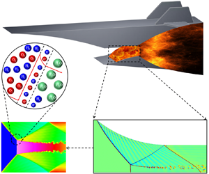
A schematic of the CDE is shown in figure 1, which is derived from the ODE by replacing the oblique wedge with a curved wall. Given that a CDW has features that are not present in an ODW, study of the CDE is valuable both from a theoretical perspective and with regard to potential applications. In this paper, the main focus is on the CDW using the computational model shown in figure 2. It is worth noting that the engine is inverted in the calculation model to make it more convenient to observe the structure of the detonation wave.

Figure 1. Simple schematic of a CDE: (a) convex case; (b) concave case.

Figure 2. Combustion chamber in a CDE: (a) convex case; (b) concave case. The solid lines indicate Mach reflection and the dashed lines regular reflection.
The geometrical parameters are set to  $H_1=100\ {\rm mm}$, $H_2=52\ {\rm mm}$ and 62 mm for convex and concave, respectively, and $L_1+L_2=210\ {\rm mm}$, and the wall curvature and $x_2$ will be changed as needed in different cases. For the selection of the geometrical dimensions, on the one hand, we refer to the dimensions in the research of Zhang et al. (Reference Zhang, Liu and Wen2022a) and Wang et al. (Reference Wang, Zhang, Yang and Teng2020), and on the other hand, we have also considered the possible dimensional constraints of the actual engine design. The fuel is a mixture of hydrogen and air with an equivalent ratio of 0.34 (Yu & Miao Reference Yu and Miao2018). A lower equivalence ratio of 0.34 is selected since fuel mixing is difficult at high supersonic conditions. The incoming flow parameters are kept constant at $p_1=100\ {\rm kPa}$, $T_1=700\ {\rm K}$ and $u_1=2495\ {\rm m}\ {\rm s}^{-1}$. The selection of the incoming flow parameters is based on an estimation, if the incoming flow before the inlet with the pressure of 6 kPa, the temperature is 200–300 K, and the velocity is Mach 9. After compression by an oblique shock with $25^{\circ }$, the postwave pressure is around 100 kPa, the temperature is around 700 K and the velocity is approximately equal to $2495\ {\rm m}\ {\rm s}^{-1}$. The inlet between $x=-0.01$ m to 0.00 m is given a supersonic flow condition, the right-hand boundary is set as a supersonic outlet.
3. Curved detonation reflection with different curvatures
Compared with the wall in oblique detonation, which can be determined by the size of the wedge angle, the curved wall in curved detonation is relatively complex, and it is difficult to make comparisons simply in terms of the wall angle. Therefore, the concept of mean curvature is introduced to measure the degree of curvature,
 \begin{equation} \kappa =\frac{\Delta \alpha }{\Delta s}=\frac{\alpha_2-\alpha_1}{s}, \end{equation}
where  $\Delta \alpha$ is the angle of curve deflection and $\Delta s$ is the arclength of the curve, as shown in figure 3. Here $\kappa$ will be taken as the main independent variable.

Figure 3. Schematic of the average curvature.
3.1. Curved detonation reflections induced by convex walls
Firstly, the convex detonation wave is taken as an example. In this part of the study, the curvature of the curved wall surface is varied by varying the  $x$ coordinate of $x_2$, and the results of the detonation reflection are calculated separately for many different cases. A wall with a large curvature is considered and the wall function is set to $y = 0.0028x^2 - 0.7278x + 100$. The mean curvature is $-0.0096$. Negative values indicate that the wave angle is decreasing. To observe the process of reflection, calculations for transient evolution are performed, with the results being shown in figure 4. For convenience, the calculation for this wall condition is referred to as case 1.

Figure 4. Transient evolution process of non-stationary Mach reflection for a convex wall condition: (a)  $t=0.0545\ {\rm ms}$; (b) $t=0.0990\ {\rm ms}$; (c) $t=0.114\ {\rm ms}$; (d) $t=0.134\ {\rm ms}$; (e) $t=0.157\ {\rm ms}$; (f) $t=0.190\ {\rm ms}$; (g) $t=0.224\ {\rm ms}$; (h) $t=0.256\ {\rm ms}$; (i) $t=0.290\ {\rm ms}$; (j) $t=0.323\ {\rm ms}$; (k) $t=0.504\ {\rm ms}$; (l) $t=0.639\ {\rm ms}$.
In figure 4, the CDW is reflected from the wall at  $t=0.0545\ {\rm ms}$, and, after a period of development, the reflected shock wave intersects the upper wall and produces a secondary reflected shock wave as shown in figure 4(b). It is noteworthy that at $t=0.114\ {\rm ms}$, a Mach stem is generated, and with time, the height of the Mach stem gradually grows and its position gradually moves forward. Finally, with the movement of the Mach stem, the detonation wave is completely pushed out of the flow field as shown in figure 4(c–l). The movement of the Mach stem has a crucial influence on the behaviour of the detonation wave, and so further analysis of its motion is necessary.
To quantitatively describe the motion of the Mach stem, the distances and corresponding velocities of the Mach stem moving in the vertical and horizontal directions at several points in time are plotted in figure 5, where the distance in the vertical direction represents the height of the Mach stem and the distance in the horizontal direction represents its position. From figures 4 and 5 together, it is easy to see that following the creation of the Mach stem, its height grows nearly linearly and with a near constant velocity of motion between  $t=0.114\ {\rm ms}$ and 0.256 ms. If a stationary state is desired, the height and distance of the Mach stem should remain constant between 0.504 ms and 0.639 ms and the velocity should gradually converge to 0, as shown by the dashed arrows in figure 5. However, during the period $t=0.504-0.639\ {\rm ms}$, the Mach stem accelerates considerably in both the vertical and horizontal directions, and this acceleration eventually leads to the Mach stem being pushed out of the flow field.

Figure 5. Motion of Mach stem in non-stationary Mach reflection for a convex wall condition: (a) vertical direction; (b) horizontal direction.
To further clarify the reason for the acceleration of the Mach stem in the final stage, the detonation flow field at  $t=0.504\ {\rm ms}$ is studied separately, as shown in figure 6. Figure 6(a) shows a numerical shadow diagram of the flow field structure, which consists of a complex system of waves. Figure 6(b) shows the Mach number contours, where the areas enclosed by the solid black lines are the subsonic zones. Figure 6(c) shows the pressure contours and figure 6(d) shows the temperature contours. Combining the four parts of figure 6 to analyse the detonation flow field at this given instant, it can be seen that there are three main subsonic zones following the wave, corresponding to the high-temperature and high-pressure zones. Subsonic zone 1 is caused by the Mach stem, with the excessive intensity of the detonation wave resulting in a high-temperature–high-pressure subsonic zone. Subsonic zone 2 is due to the curvature of the wall resulting from the large angle of the detonation wave, similar to subsonic zone 1. Subsonic zone 3 is caused by the reflected shock wave and secondary reflected shock wave. On the one hand, the subsonic zone 2 causes instability of the CDW. On the other hand, subsonic zone 3 intersects subsonic zone 1 through the slip line, further increasing the pressure ratio behind the Mach stem and driving the Mach stem to accelerate forward to match the increased pressure ratio. As a result, both the Mach stem and the CDW become destabilized.

Figure 6. Non-stationary Mach reflection flow field for a convex wall condition at  $t=0.504\ {\rm ms}$: (a) shadowgraph; (b) Mach number contours; (c) pressure contours; (d) temperature contours.
The above analysis indicates that there are two main aspects to the effect of curvature: first, a large curvature leads to a large wave angle, generating a high-temperature–high-pressure subsonic zone, which is not beneficial to the stability of the detonation wave; second, a large curvature also leads to an early position of the secondary reflection shock wave (together with an increased intensity), intersecting with the subsonic zone behind the Mach stem through the slip line and further disturbing the stability of the detonation wave.
From the above results, it can be seen that moving  $x_2$ to the right reduces the wall curvature. The wall function becomes $y = 0.0085x^2 - 1.2531x + 100$. The mean curvature $\kappa$ is $-0.0045$. Keeping the other calculation conditions unchanged, the transient reflected flow field is obtained as shown in figure 7. It can be seen that at $t=0.0683\ {\rm ms}$, the CDW is reflected by contact with the wall, and, as time passes, at $t=0.132\ {\rm ms}$, the reflected shock wave comes into contact with the upper wall, with a secondary reflected shock wave being generated near the exit. Then, with the forward propagation of the detonation wave, a Mach stem gradually forms: at $t = 0.164\ {\rm ms}$, a tiny Mach stem appears, acquires a well-defined shape at $t =0.219\ {\rm ms}$ and then grows while propagating forward, with its speed of motion in both directions gradually slowing down until it is stabilized at $t=0.634\ {\rm ms}$. The distance and speed of the Mach stem motion in both vertical and horizontal directions during this process are shown in figure 8, from which it is easy to see that the distances travelled in both directions gradually increase and finally become stable, with the velocity of motion gradually decreasing after reaching a peak and finally approaching zero.

Figure 7. Transient evolution process of stationary Mach reflection for a convex wall condition: (a)  $t=0.0683\ {\rm ms}$; (b) $t=0.132\ {\rm ms}$; (c) $t=0.164\ {\rm ms}$; (d) $t=0.219\ {\rm ms}$; (e) $t=0.283\ {\rm ms}$; (f) $t=0.347\ {\rm ms}$; (g) $t=0.395\ {\rm ms}$; (h) $t=0.443\ {\rm ms}$; (i) $t=0.507\ {\rm ms}$; (j) $t=0.539\ {\rm ms}$; (k) $t=0.586\ {\rm ms}$; (l) $t=0.634\ {\rm ms}$.

Figure 8. Movement of Mach stem of stationary Mach reflection for a convex wall condition: (a) vertical direction; (b) horizontal direction.
From figure 8, it is easy to see that both non-stationary and stationary Mach reflections have similar patterns of motion in the early stages of development of the Mach stem. The difference lies in the acceleration process of the Mach stem in the middle and late stages. This different behaviour arises because the different curvature of the wall surface leads to a different curvature of the detonation wave, and therefore a different structure of the flow field reflected by the detonation wave.
To enable a clearer analysis, figure 9 is plotted. The flow field structure in figure 9(a) is different from that in figure 6(a), with a significantly lower angle for both the detonation wave and the reflected shock wave, as well as a much simpler wave system structure. Figures 9(a) and 9(b) together reveal that the flow field has only two subsonic zones, located behind the Mach stem and the secondary reflected shock wave. The zones of high temperature and pressure have also been reduced, as shown in figure 9(c,d). On comparing figure 9 with figure 6, it can be seen that along with the decrease in wall curvature, the subsonic zone after the detonation wave has disappeared and the secondary reflection shock wave no longer intersects the subsonic zone behind the Mach stem. Both detrimental conditions are eliminated, and so the detonation wave reflection can finally be stationary. Retaining the above geometric conditions of Mach reflection, the curvature of the wall surface is reduced further, and the corresponding detonation wave flow field is calculated. The wall function becomes  $y = 0.0013x^2-0.5126x + 100$. The mean curvature $\kappa$ is now $-0.0022$.

Figure 9. Stationary Mach reflection flow field for a convex wall condition at  $t=0.634\ {\rm ms}$: (a) shadowgraph; (b) Mach number contours; (c) pressure contours; (d) temperature contours.
The structural evolution of the detonation waves in figure 10 shows that the regular reflection of the detonation wave flow field structure is simple and stable for a short time. In figure 10(a), the detonation wave is reflected on the lower wall surface, and with the advance of time, the reflected wave angle is gradually increased. At 0.144 ms, the reflected wave is close to the upper wall, and at the next instant, 0.172 ms, the reflected wave is reflected on the upper wall and a secondary reflection shock wave is formed. Thereafter, the secondary reflection shock gradually moves forward and the flow field stabilizes (0.268 ms) until the end of the process. It is clear from observing the entire flow field that the structural evolution of the wave system centres mainly around the establishment and stabilization of the reflected and secondary reflected shock waves. To understand the reasons for this and to get a clearer view of the overall flow field, figure 11 is plotted. In figure 11(a), the wave structure of the flow field is shown, from which it can be seen that there is no subsonic zone anywhere in the flow field and also that the high temperature is reduced compared with figure 9. The main reason for this is the reduced angle of the detonation wave, with the reflection point being shifted back such that the detachment criterion is no longer satisfied and therefore no Mach reflection occurs.

Figure 10. Transient evolution process of regular reflection for a convex wall condition: (a)  $t=0.0645\ {\rm ms}$; (b) $t=0.144\ {\rm ms}$; (c) $t=0.172\ {\rm ms}$; (d) $t=0.268\ {\rm ms}$.

Figure 11. Regular reflection flow field: (a) shadowgraph; (b) Mach number contours; (c) pressure contours; (d) temperature contours. The EW is expansion wave (EW).
By comparing the structure and evolution of the wave system for regular reflection and Mach reflection, it can be seen that the structure of the regular reflection wave system is simple and stable for a short time, which is more beneficial to the stationarity of the detonation wave in the combustion chamber. To represent the effect of curvature on the detonation reflections more clearly, figure 12 is plotted.

Figure 12. Effect of curvature on detonation reflection for a convex wall condition: DW, detonation wave; RS, reflected shock; SRS, secondary reflected shock; MS, Mach stem.
The effect of curvature is manifested in two ways, namely the angle and the position of the wave. The angle of the wave affects the aerodynamic state behind the wave, with the subsonic zone appearing when it is too large and turning into a supersonic zone when it is reduced. Interaction occurs when they are too close together (the secondary reflected shock intersects the subsonic zone behind the Mach stem), but not when they are far away. When the subsonic zone is too large and interaction occurs, non-stationary Mach reflection occurs, and conversely when the subsonic zone is small and no interference occurs, the reflection is stationary (Mach reflection and regular reflection), as shown in table 1.
Table 1. Situation regarding stationarity of a CDW for convex wall conditions at different curvatures.

3.2. Curved detonation reflections induced by concave walls
Following the above investigation of reflection in the case of a wall with convex curvature, reflection by a concave curved wall is considered. Since such reflection results in a particularly pronounced induced zone and a reflection position that is farther back than for a convex wall, the same exit height as for a combustion chamber with a convex curved wall would not give a consistent reflection result. Therefore,  $H_2$ is increased to 62. Again, a variety of curved deflection fields are calculated by varying the mean curvature. First, the $x$ coordinate of $x_2$ is held constant at a value of 62, and the concave curved detonation reflection flow field with the average curvature of $x$ under this condition is calculated as shown in figure 13. It can be seen that at $t=0.0605\ {\rm ms}$, the detonation wave produces a reflected shock on contact with the lower wall surface, which is followed by a gradual growth to the exit height. Then, at $t = 0.155\ {\rm ms}$, there is a secondary reflection and at the same time the structure of a Mach stem appears, which gradually increases in height while its position moves forward. With advancing time, at $t = 0.536\ {\rm ms}$, the CDW is eventually completely transformed into a Mach stem.

Figure 13. Transient evolution process of non-stationary Mach reflection for a concave wall condition: (a)  $t=0.0605\ {\rm ms}$; (b) $t=0.0873\ {\rm ms}$; (c) $t=0.114\ {\rm ms}$; (d) $t=0.155\ {\rm ms}$; (e) $t=0.195\ {\rm ms}$; (f) $t=0.236\ {\rm ms}$; (g) $t=0.277\ {\rm ms}$; (h) $t=0.331\ {\rm ms}$; (i) $t=0.401\ {\rm ms}$; (j) $t=0.442\ {\rm ms}$; (k) $t=0.488\ {\rm ms}$; (l) $t=0.536\ {\rm ms}$.
For further quantitative analysis of the motion of the Mach stem, this motion in the vertical and horizontal directions at various instants of time is shown in figure 14. It can be seen that the height and position of the Mach stem continue to change until the height reaches a maximum value. The variations of the corresponding speeds are relatively complex, indicating the complex nature of the changes in the flow field.

Figure 14. Movement of Mach stem of non-stationary Mach reflection for a concave wall condition: (a) vertical direction; (b) horizontal direction.
To investigate why the Mach reflection is not stationary in this case, the flow field results at  $t= 0.236\ {\rm ms}$ are considered and the behaviour of the CDW is analysed as shown in figure 15. It can be seen from figure 15(a) that the wave system of the flow field is relatively complex, owing to the small initial angle of the wedge surface. As well as an induced shock (IS), it can be seen from figure 15(a) together with figure 15(d) that the detonation wave can be divided into four parts: the first part (CDW1), with low strength, is located after IS; in the second part (CDW2), the wave angle increases nearly to oblique detonation; the third part (CDW3) has an obvious curvature, and the wave angle also increases further; the fourth part (MS) is the Mach stem, which is almost vertical to the wall. In addition, there are a series of compressional waves (CW) generated by the curved wall, two reflected shocks (RS1 and RS2) and two secondary reflected shocks (SRS1 and SRS2), as well as two slip lines (SL and SSL) in the flow field. The two main subsonic zones can be seen in figure 15(b), located after CDW2 and the Mach stem, respectively, which are also caused by the large angle of the two detonation waves. These two subsonic zones also have a tendency to merge, which is detrimental to stationarity. The high-pressure region resulting from the compressional waves and Mach stem is shown in figure 15(c), which also shows once again the influence of the curved wall, with the convergence of compressional waves leading to the appearance of a high-pressure region.

Figure 15. Non-stationary Mach reflection flow field at  $t=0.236\ {\rm ms}$: (a) shadowgraph; (b) Mach number contours; (c) pressure contours; (d) hydrogen contours.
Further, the flow field at four selected instants of time from 0.114 ms to 0.331 ms is shown in figure 16, and both the subsonic and high-pressure zones gradually expand and integrate, accompanied by the non-stationary detonation wave. Similar to what was observed in the case of a convex wall, there are three subsonic zones: behind the detonation wave; behind the reflection wave; behind the Mach stem. Unlike the previous case, however, the high-pressure zone is concentrated near the wall where the compressional waves converge, as well as in the area behind the Mach stem. Although the structure of the wave system is different for the different wall curvatures, the reasons for the non-stationary structure are similar: the expansion and integration of multiple subsonic/high-pressure zones lead to a gradual increase in the detonation wave angle to match the unbalanced pressure ratio until the detonation wave meets the Mach stem. To check this explanation, the oblique detonation flow field is calculated under the same conditions, with the results being shown in figure 17, from which it is clear that stationary Mach reflection occurs for the oblique wall case. Comparison shows that since the wall has no curvature and therefore no compressional waves are generated, and thus the high-pressure zone near the wall is missing, the detonation wave angle does not have to increase as a result and no subsonic zone is generated behind the wave. Ultimately, the Mach reflection can be stationary. This comparison illustrates that a curved wall surface will not only cause curvature of the detonation wave, but also generate non-negligible compressional waves.

Figure 16. Pressure contours of the flow field at different instant for the case of a concave wall: (a,b)  $t=0.114\ {\rm ms}$; (c,d) $t=0.195\ {\rm ms}$; (e,f) $t=0.236\ {\rm ms}$; (g,h) $t=0.331\ {\rm ms}$.

Figure 17. Oblique detonation flow field with stationary Mach reflection: (a) shadowgraph; (b) Mach number contours; (c) pressure contours; (d) temperature contours. EW means expansion wave (EW).
To explore the effect of curvature, the average curvature of the curved wall surface is reduced further to increase the horizontal coordinate of  $x_2$ to 122 mm, and the calculated detonation wave standing reflection flow field is shown in figure 18. Figures 18 and 19 both show that the concave CDW at this degree of wall curvature is a stationary Mach reflection in the combustion chamber and that the height of the Mach stem is significantly reduced compared with that in the previous case with greater wall curvature.

Figure 18. Transient evolution process of stationary Mach reflection for a concave wall condition: (a)  $t=0.0525\ {\rm ms}$; (b) $t=0.104\ {\rm ms}$; (c) $t=0.113\ {\rm ms}$; (d) $t=0.131\ {\rm ms}$; (e) $t=0.160\ {\rm ms}$; (f) $t=0.210\ {\rm ms}$; (g) $t=0.236\ {\rm ms}$; (h) $t=0.293\ {\rm ms}$; (i) $t=0.350\ {\rm ms}$; (j) $t=0.438\ {\rm ms}$; (k) $t=0.453\ {\rm ms}$; (l) $t=0.585\ {\rm ms}$.

Figure 19. Motion of Mach stem of stationary Mach reflection for a concave wall condition: (a) vertical direction; (b) horizontal direction.
At smaller wall curvatures, the structure of the stationary detonation wave illustrated in figure 20 is simpler than that of the non-stationary, and there is a significant reduction in the areas of the subsonic and high-pressure zones. As the curvature of the wall decreases, the length of the induced zone increases significantly, which results in more compressional waves appearing before the detonation wave, i.e. the position of the detonation wave is driven back. This weakens the effect of the compressional waves after the detonation wave, there is no longer a high-pressure zone after the wave, the wave angle does not have to increase continuously, and a subsonic zone is no longer generated. In addition, as the position of the detonation wave is pushed back, the position of the reflected wave is also moved back, the pressure increase caused by the reflected wave will not act directly after the detonation wave, and the high-pressure zone after the detonation wave is further reduced and stability is improved.

Figure 20. Mach reflection flow field of stationary detonation wave at  $t=0.585\ {\rm ms}$: (a) shadowgraph; (b) Mach number contours; (c) pressure contours; (d) hydrogen contours.
The effect of wall curvature on the detonation reflection is summarized in figure 21, from which, similarly to figure 12, it can be seen that the wall surface affects the angle and position of the wave. In contrast to the case of a convex wall surface, however, reflection from a concave wall surface involves effects of compressional waves on the detonation wave and effects of the high-pressure zone that are present after the reflected shock wave.

Figure 21. Effect of curvature on detonation reflection for a concave wall condition: CW, compressional wave; DW, detonation wave; RS, reflected shock.
Further reducing the wall curvature results in multiple sets of stationary Mach reflections, as shown in figure 22 and table 2. This behaviour is similar in general to that observed for higher curvature, but there is a significant difference in the height of the Mach stem. To examine the effect of curvature on the Mach stem height, figure 23 is plotted, where the black dots are the simulation results and the red line is a linear fit. Although there is no specific explicit relationship between curvature and Mach stem height, there is a clear correlation between the two. In this paper, the relationship between curvature and Mach stem height will be investigated through a theoretical modelling approach.

Figure 22. Mach reflection for different curvatures of the detonation flow field: (a)  $\kappa =0.004$; (b) $\kappa =0.0038$; (c) $\kappa =0.0029$; (d) $\kappa =0.0027$; (e) $\kappa =0.0023$; (f) $\kappa =0.0021$.

Figure 23. Relationship between Mach reflection height and curvature for a concave wall condition. CFD is computational fluid dynamics (CFD).
Table 2. Situation regarding stationarity of a CDW for concave wall conditions at different curvatures.

3.3. Analyses of flow mechanisms related to choked flow
Based on the above analysis, it can be realized that the interference in the subsonic region behind the Mach stem has a significant effect on the stabilization of the Mach stem. By further investigation it can be found that the underlying physics of the non-stationary Mach stem is the choked flow. For an ideal compressible gas, the mass flow rate can be calculated,
 \begin{equation} \overset{\bullet }{\mathop{m}}\,=\frac{A{{p}_{t}}}{\sqrt{{{T}_{t}}}}\sqrt{\frac{\gamma }{R}}M{{\left(1+\frac{\gamma -1}{2}{{M}^{2}}\right)}^{-(({\gamma +1})/{2(\gamma -1)})}}, \end{equation}
where  $A$ is the area, $R$ is the gas constant, $T_t$ is the total temperature, $\gamma$ is the specific ratio, $M$ is Mach number, $p_t$ is the total pressure. Mass flow rate is a maximum when $M$ = 1, at these conditions,
 \begin{equation} {{\overset{\bullet }{\mathop{m}}\,}_{max }}=\frac{A{{p}_{t}}}{\sqrt{{{T}_{t}}}}\sqrt{\frac{\gamma }{R}}{{\left(\frac{\gamma +1}{2}\right)}^{-(({\gamma +1})/{2(\gamma -1)})}}. \end{equation}
 According to the (3.2) and (3.3), it is clear that the mass flow rate should be less than the maximum value if the flow is not choked. In order to better explain the effect of choked flow on the standing of the Mach reflection, the following example is analysed. With respect to the two flow fields shown in figure 24, the Mach number  $M$ behind the Mach stem and the height $A_1$ can be calculated from the numerical results, which allows for the calculation of the flow rate through the Mach stem. The height $A_{2t}$ can be calculated from (3.2), which corresponds to the situation when the velocity at the throat reaches the speed of sound. Comparing this value with the height $A_{2s}$ of the actual throat from simulation result, it is possible to know whether or not the airflow will be choked. If $A_{2s}$ is greater than $A_{2t}$, the airflow will not be choked, and on the contrary, if $A_{2s}$ is less than $A_{2t}$, choking will occur. Specific calculations are placed in table 3.

Figure 24. Contours of Mach number in the flow field: (a) non-stationary Mach reflections on concave wall, (b) stationary Mach reflections on convex wall.
Table 3. Comparison of heights at the Mach reflection throat for curved detonations.

In table 3, for the flow field of the reflected detonation wave generated from the concave wall, the velocity behind the Mach stem is 0.445 Mach, and the Mach stem height is 0.0635 m. According to the calculation, the minimum throat height at the speed of sound can be calculated to be 0.0430 m, whereas the height of the throat in the flow field is 0.0367 m, which is significantly less than the theoretical value. Therefore, this flow field is choked and the airflow cannot be stabilized through the throat, so the throat height needs to grow continuously, which leads to a continuous increase in the Mach stem height, which in turn results in the non-stationary Mach reflection. Regarding the flow field of the reflected detonation wave generated by the convex wall, the velocity behind the Mach stem is 0.446 Mach, the height of the Mach stem is 0.0229 m, and the  $A_{2s}$ is 0.0157 m slightly larger than the $A_{2t}$ of 0.0155 m, so the airflow will not be choked, and the Mach reflections will be stationary as a result. Apart from the choked flow in two transient flow fields in figure 24, to further understand the contribution of the choked flow in the detonation reflection, the choked situation at different moments in the detonation reflection is also calculated and plotted, as shown in tables 4, 5 and figure 25, respectively.
Table 4. Choked situation of the curved detonation reflected flow field on a concave wall at different moments.

Table 5. Choked situation of the curved detonation reflected flow field on a convex wall at different moments of time.


Figure 25. Variation of choked flow in the reflected flow field of CDWs at different moments of time.
According to tables 4, 5 and figure 25, it can be observed that for the non-stationary curved detonation reflection (concave wall), the airflow has been in the choked condition and the gaps are oscillated around  $-0.20$. While for the stationary curved detonation reflection (convex wall), the airflow starts off with choke as well, and as time progresses, the choked flow has been improving. The gaps keep an overall upward trend and eventually stabilize near 0 as well as at positive values. With the above analysis, it can be concluded that the choked flow significantly causes the non-stationary situation of the detonation reflections.
4. Analysis of postwave flow parameters for curved detonation reflection
Curvature not only affects the reflection of a detonation wave, but also changes the postwave flow properties. In this section, the effect of curvature on postwave flow is investigated by analysing simulation results. In the next section, the relationship between curvature and the gradient of the wave wake flow is obtained using a theoretical derivation.
4.1. Postwave flow parameters induced by convex walls
Figure 26 is taken as an example to analyse the regular reflection of the curved detonation from figure 11. From figure 26(a), it can be seen that the overall structure of the flow field is similar to that in figure 26(c) and the effect caused by curvature is not obvious. However, extraction of the data on the streamlines reveals that the curvature of the wall causes a significant change that can be seen in figure 26(b,d). Compared with an ODW, with a similar flow field structure, the difference in airflow variation is caused mainly by the curvature. This also proves that even a small curvature can have a large effect on the postwave flow.

Figure 26. Regular reflection: (a) flow field in a CDW; (b) parameters on a streamline in a CDW, where the red line is pressure, the green line is the deflection angle and the blue line is the mass fraction of hydrogen; (c) flow field in an ODW; (d) parameters on a streamline in an oblique detonation wave.
In addition to the regular reflection, the difference between CDW and ODW in the Mach reflection flow field is also worth studying. Figure 27(a) shows the structure of the flow field and its streamline 1, 2 when Mach reflection occurs in the CDW, and figure 27(b) shows the structure of the flow field and its streamline 3, 4 when Mach reflection occurs in the ODW. In the overall structure of the flow field, the CDW and the ODW are similar, which both consist of the detonation wave, reflected shocks, the Mach stem, the slip line, etc. Unlike the similarity in the overall structure, there are differences in the flow characteristics, and figure 28(a–d) show the parameters on streamline 1–4, respectively.

Figure 27. Flow field of Mach reflections along with their streamlines: (a) CDW; (b) ODW.

Figure 28. Parameters on the streamlines in the Mach reflections: (a) streamline 1 of the CDW; (b) streamline 2 of the CDW; (c) streamline 3 of the ODW; (d) streamline 4 of the ODW.
On the streamline 1 of the CDW, the pressure firstly jumps to 1.6 MPa at point  $A_1$ after passing through the CDW, and then the pressure after the postdetonation wave continuously decreases to 0.72 MPa before point $B_1$ due to the curved wall effect. After the reflection shock, the pressure rises to 1.4 MPa at point $B_1$. Then, the pressure decreases again to 9.8 MPa. It reaches 1.5 MPa at point $C_1$ after the secondary reflection shock. Before the outlet, the pressure rises to 1.3 MPa after the third reflection shock. Similarly, on streamline 3 of the ODW, the postwave pressure rises by the action of the ODW to approximately 1.3 MPa at $A_3$, and then remains near the stabilization value of 1.25 MPa. The pressure then decreases to approximately 0.8 MPa at point $B_3$ due to the action of the wedge-tailed expansion wave, and the action of the reflection shock causes the pressure to rise to a peak value near 1.4 MPa at point $C_3$. Thereafter it continues to experience the action of the expansion wave, causing the pressure to decrease continuously to approximately 0.51 MPa at point $D_3$. The pressure then undergoes a brief period of rise to approximately 0.6 MPa at $E_3$, and the secondary reflection shock causes the pressure to continue to rise and remain essentially at approximately 1.1 MPa until $F_3$. The pressure then rises and then falls, reaching approximately 1.3 MPa at $G_3$. In the streamline 2 of the CDW, the pressure jumps to approximately 2.25 MPa at $A_2$ through the action of the Mach stem, and the flow decreases below the sound speed up to the point $B_2$. After that, the pressure undergoes two jumps to reach 1.2 and 1.5 MPa at $C_2$ and $D_2$, respectively, due to the action of the secondary and third reflection shocks. On the streamline 4 of the ODW, the airflow also undergoes the action of the Mach stem which causes the pressure to rise to approximately 2.25 MPa at $A_4$, and the velocity decreases below the sound speed up to point $B_4$. Due to the fact that the position of the secondary reflection shock is more backward, the secondary reflection shock is further back, the airflow only passes through the action of the single reflection shock to reach 0.89 MPa at $C_4$.
According to the above analysis, it can be concluded that there are both similarities and significant differences between the Mach reflections of CDW and OCW. For example, the pressure peaks after the Mach stem are close, while the pressure after the detonation wave are different. In addition, the locations of the expansion waves are different, where the ODW forms significant wedge-tailed expansion waves in the places where the wall turns horizontal, while the expansion waves of the CDW are widely distributed. Besides, there are also disagreements in terms of the number of subsonic zones and outlet pressures.
4.2. Postwave flow parameters induced by concave walls
In the regular reflection shown in figure 29, there are two types of detonation waves in the form of a secondary CDW (SCDW) and a CDW. It is easy to see that the SCDW undergoes a curved shock and multiple compressional wave actions before combustion. These may affect the strength and shape, and to investigate this and the differences between the two detonation waves, two streamlines are extracted as shown in figure 30.

Figure 29. Regular reflection of the curved detonation for a concave wall condition: (a) shadowgraph; (b) temperature contours.

Figure 30. Parameters on the streamlines of regular reflection for a concave wall condition.
In figure 30, the detonation wave of streamline 1 is subject to the effects of the curved shock and compression waves, resulting in a non-uniform incoming flow of the detonation wave and a large increase in pressure. The CDW is straight because the incoming flow is uniform, and the pressure after the wave is lower than that of the SCDW. However, it is worth noting that the mass fraction of hydrogen increases on streamline 2 as the flow goes through the reflected shock. This phenomenon implies that the chemical reaction proceeds in the reverse direction owing to the pressure and temperature increase caused by the reflected shock and the presence of water decomposition. Unlike the case of regular reflection, the flow field resulting from Mach reflection is more complex. There is not only a CDW, but also a Mach stem and slip line, and other structures are also present, as can be seen in figure 31, where there are three detonation waves on this streamline.

Figure 31. Mach reflection of curved detonation for a concave wall condition.
In figure 32(a), the streamline first passes through a curved shock generated by the curved wall, and the pressure is increased, but no chemical reaction takes place. After this, the pressure is further increased by a compression wave generated by the curved wall, and the conditions for detonation combustion are reached, with the result that detonation combustion occurs immediately afterwards, and the pressure is further increased and the mass fraction of hydrogen decreases very rapidly. In figure 32(b), the streamline passes directly through the detonation wave that has been formed. After this, the streamline passes through the compressed postwave flow field and intersects the reflected shock wave, and the pressure rises further to reach a peak. Thereafter, the airflow continues to decrease in pressure towards the exit. In figure 32(c), the detonation wave at this time is in the form of a Mach stem, and by comparing the pressure with those in figure 32(a,b), it is easy to see that the detonation is more intense at this time. This streamline representing change of state is also relatively simple, with the pressure after the Mach stem decreasing continuously until the exit. In figure 32(d), the folding line first passes through the curved shock and expansion wave, and this is followed by type I detonation on streamline 1. Note that in the gap regions in figure 32(d), meaningless vertical parts of the streamline data have been omitted for clarity. In the second horizontal section of streamline 2, type II detonation occurs. In the third horizontal region of streamline 3, type III detonation occurs. From a comparison of the three types of detonation, it is easy to see that there are significant differences in detonation intensity. This is because the incoming flow in type I detonation is enhanced by a series of compression waves, and the pressure and temperature are significantly increased.

Figure 32. Parameters of curved detonation for a concave wall condition: (a) streamline 1; (b) streamline 2; (c) streamline 3; (d) comparison.
4.3. The potential benefits of CDE compared with ODE
According to the findings in this research, it can be found that CDEs may have the following advantages. Firstly, compared with ODE, CDE has a shorter induction distance. In the case of convex wall surfaces, the detonation wave has almost no significant structure of the induction zone due to the large start detonation wave angle. In order to demonstrate this advantage more clearly, we give the comparison results. In figure 33, ODE has a significant IS, while CDE has no induced zone. A more obvious comparison can be found in figure 34. A shorter induction zone means that the fuel can be better used, which is good for the engine. Secondly, compression/expansion waves can be utilized wisely. In CDE, curved wall surfaces will inevitably generate expansion/compression waves. The expansion wave generated by the convex wall surface can reduce the overdrive degree of the detonation wave. For actual detonation engines, CJ (Chapman–Jouguet) detonation is difficult to realize, so usually an overdriven detonation wave is the main choice. The expansion wave generated by the curved wall surface can effectively reduce the overdrive degree of the detonation wave, which is beneficial to increase the propulsion performance of the detonation engine. Unlike the expansion wave, compression waves generated by concave wall surfaces can contribute to detonation. A compression wave has the effect of increasing temperature and pressure, which can help the detonation wave to achieve the conditions of combustion. In short, CDE can use the expansion/compression wave to achieve the purpose of reducing overdrive degree/promoting the detonation, etc., these are not the advantages of ODE. Furthermore, curved walls offer a more flexible adjustment strategy compared with oblique walls. It is well known that curves are more flexible than straight lines. As shown in figure 35(a), for ODW, when we want to make changes, we can only choose to increase or decrease its wave angle. For CDW, we have more choices, we can choose to increase/decrease the wave angle 1 or increase/decrease the wave angle 2, and we can also make changes to its curvature. In addition, as shown in figure 35(b), the detonation waves when two CDWs with different curvatures are combined together has more flexibility. The greater degree of freedom means that the detonation wave morphology can be designed more flexibly according to the incoming flow conditions or working conditions to meet the needs of CDE, all of which obviously cannot be achieved by ODE.

Figure 33. Comparison of the flow field between the ODE and CDE when  $x_2=155$: (a) shadowgraph of the ODE; (b) temperature contours of the ODE; (c) hydrogen mass fraction of the ODE; (d) shadowgraph of the CDE; (e) temperature contours of the CDE; (f) hydrogen mass fraction of the CDE.

Figure 34. Comparison of the flow field between the ODE and CDE when  $x_2=173$: (a) shadowgraph of the ODE; (b) temperature contours of the ODE; (c) hydrogen mass fraction of the ODE; (d) shadowgraph of the CDE; (e) temperature contours of the CDE; (f) hydrogen mass fraction of the CDE.

Figure 35. Variation strategy of CDW and ODW.
5. Effect of curvature on postwave flow parameters
From the above analysis of the curved detonation reflection flow field, it is clear that curvature has a significant effect on the postwave parameters. However, it is difficult to determine the magnitude of this effect directly from the simulation results, and it is therefore necessary to carry out a theoretical analysis. The curved detonation shown in figure 36 is considered, and the wavefunction is denoted by  $y = f (x)$. In figure 36, the wave angle $\beta$ is the angle between the tangent line to the CDW curve and the horizontal line, and therefore can be found,
 \begin{equation} \beta =\arctan y', \end{equation}
from which the derivative of the wave angle with respect to the coordinate  $x$ is
 \begin{equation} \frac{\partial \beta }{\partial x}=\frac{y''}{1+y'^2}. \end{equation}
From the geometry of the system, the curvature of the wave is then given by
 \begin{equation} S=\frac{y''}{(1+ y'^2)^{3/2}} \end{equation}
(it should be noted here that  $S$ is the curvature of the wave and is to be distinguished from the wall curvature $\kappa$). Therefore,
 \begin{equation} \frac{\partial \beta }{\partial x}=S\sqrt{1+y'^2}. \end{equation}
According to the typical gas-dynamic theories involving heat release, the gradient of the pressure and airflow deflection angle in the  $x$-direction can be easily derived.

Figure 36. Schematic of curved detonation reflection wave system.
5.1. Analysis of postwave gradients
The derivatives of the postwave parameters obtained above can be used in further analysis. According to typical gas-dynamic theories, these derivatives are mainly affected by the incoming Mach number and wave angle. For a convex curvature, the postwave gradients of pressure and deflection angle vary with Mach number as shown in figure 37. The waveform is
 \begin{equation} y=17.68x^2-2.24x+0.068,\quad x=0.025 \end{equation}
and the calculation conditions are
 \begin{equation} p_1=0.98\,\text{atm},\quad M_1=[5:0.5:10],\quad \gamma_1=1.34,\quad \gamma_2=1.27. \end{equation}
Figure 37. Changes in gradients with Mach number for a convex wave condition: (a) pressure and pressure gradient; (b) deflection angle and its gradient. The waveform function is  $y = 17.68{x^2} - 2.24x + 0.068$ and the parameters are extracted at the point $x=0.025$.
In figure 37, the values of the parameters are extracted from a fixed point of  $x=0.025$ under a given Mach number. As the Mach number increases, the pressure decreases along the detonation wave and the airflow deflection angle increases. This means that if the shape of the detonation wave remains constant, the change in pressure gradient along the wave increases with increasing Mach number. This is consistent with the change from Mach reflection to regular reflection with increasing Mach number. For the airflow deflection angle, as the Mach number increases, the change in airflow deflection along the $x$ direction is also gradually increasing. This means that for an originally stationary Mach reflection, an increase in Mach number may lead to a downward movement of the triple-wave point and an overall decrease in the slip line. Thus, a transition from Mach reflection to regular reflection occurs.
The gradients of pressure and airflow deflection angle for a concave curvature are shown in figure 38. The waveform is
 \begin{equation} y = 17.68{x^2} - 2.24x + 0.068, \quad x = [0.00045:0.002:0.025] \end{equation}
and the calculation conditions are
 \begin{equation} p_1 = 0.98\,\text{atm}, \quad M_1 = 4.6, \quad \gamma_1 = 1.34, \quad \gamma_2 = 1.27. \end{equation}
Figure 38. Changes in gradients with Mach number for a concave wave condition: (a) pressure and pressure gradient; (b) deflection angle and its gradient.
For CDWs, the curvature increases as  $x$ increases, resulting in a decrease in the wave angle. Therefore, the pressure decreases, which is easy to understand. However, the gradient of pressure exhibits non-monotonic behaviour, with the curvature first increasing and then decreasing in absolute value. From the equation for the pressure gradient, it can be seen that the pressure gradient is related to pressure and curvature. Therefore, the decrease in pressure and the increase in curvature act together to cause the non-monotonic variation. The airflow deflection angle decreases with increasing wave angle, which is again understandable, but the gradient of the deflection angle increases, because the curvature increases, and although the wave angle is decreasing, the change in the wave angle increases along the $x$ direction. According to above analysis, the gradient of the airflow deflection angle is affected by the gradient of the wave angle.
5.2. Application of the postwave gradients
The method derived in this paper can also be used to analyse simulation results. As shown in figure 39(a), several streamlines in the flow field of the curved detonation are selected, and the data on these streamlines are extracted as shown in figure 39(b). The left-hand axis represents the pressure on the streamlines, and the right-hand axis represents the mass fraction of hydrogen. To extract the postwave data, the postwave position is taken as the position at the time when the hydrogen mass fraction drops by 95 % or more. Taking the first streamline as an example, the hydrogen mass fraction at the postwave position is 0.000307 and the incoming flow is 0.00987. At this point, the hydrogen mass fraction has dropped by 97 % and the pressure remains stable even after experiencing a drop, so this is considered as the postwave state. Using this method, it is possible to extract pressure data on multiple streamlines. At the same time, a function of the detonation wave can be fitted based on the simulation results. According to the equations derived in this paper, the pressure and pressure gradient behind the incident wave can be obtained by incorporating the above-mentioned calculation parameters as shown in figure 40.

Figure 39. Curved detonation reflection flow field and parameters on streamlines: (a) temperature contours; (b) pressure and hydrogen mass fraction on the streamlines.

Figure 40. Comparison between theoretical and simulation results: (a) pressure and pressure gradient; (b) variation in curvature and wave angle.
In figure 40(a), the blue curve shows the pressure change after the wave, and a comparison with the streamline data reveals that they are in good agreement, which indicates that the calculation of the zeroth-order parameter is reliable. The red curve shows the pressure gradient after the wave, with the negative sign meaning that the pressure is gradually decreasing along the  $x$ direction, which is also consistent with the behaviour in figure 27. From figure 40(b), it is found that the pressure decreases owing to the gradual decrease in the wave angle along the $x$ direction. The absolute value of the pressure gradient is also gradually decreasing, which means that the pressure change is gradually decreasing along the $x$ direction, which is also the same as the behaviour represented by the blue curve. Based on the typical gas-dynamic theories involving heat release, it can be seen that the pressure gradient can be influenced by several variables simultaneously: pressure, wave angle, curvature, etc. In figure 40, although the curvature increases along the $x$ direction, the wave angle and pressure are both decreasing, which ultimately leads to a decrease in the pressure gradient.
Similarly, the airflow deflection angles on each streamline extracted according to the above method are shown in figure 41(a). The deflection angle of the incoming flow is  $0^{\circ }$, and after the CDW, there is a downward deflection of the flow, followed by a gradual decrease in the deflection angle due to the effect of the expansion wave. To investigate the change in deflection angle at different positions on the CDW, the deflection angle and its gradient are obtained. The results are shown in figure 41(b), where the blue curve represents the airflow deflection angle and the red curve the derivative of this angle with respect to the $x$ coordinate. The deflection angle exhibits an overall increasing trend, the rate of which can be seen from the derivative. From the red curve, it can be seen that the derivative rises and then falls, indicating the complex behaviour of the deflection angle along the CDW.

Figure 41. Comparison between theoretical and simulation results: (a) data on streamlines; (b) comparison of deflection angle with its gradient.
These comparisons and analyses demonstrate that the relationship between pressure gradient and curvature derived in this paper can be used not only as a tool for the qualitative analysis method, but also for quantitative calculations of the gradient behind a CDW. Understanding the non-uniform variation after the CDW from a higher-order level contributes to further analysis of detonation wave reflection and its potential applications.
6. Theoretical study of the effect of curvature on curved detonation reflection
The above observations and analysis of the phenomenon of detonation reflection have shown that curvature can significantly affect the reflection of detonation waves, especially the stationary Mach stem. These phenomena are interesting and complex, and so their theoretical modelling and analysis are important tasks.
6.1. Development of a quantitative criterion for curved detonation Mach reflection
To analyse the effect of curvature on the state of the Mach stem, non-stationary and stationary Mach stem structures are selected as shown in figure 42. In figure 42,  $H_s$ denotes the height of the Mach stem and $H_t$ denotes the height at the end of the subsonic zone, indicating the overall downward deflection of the subsonic zone. It can be seen that the ratio of the two heights $H_t$/ $H_s$ is approximately 0.22 when the Mach stem is non-stationary, while this ratio is increased to 0.66 when the Mach stem is stationary. The overall deflection angle in the subsonic zone is $12.6^{\circ }$ in the non-stationary case and decreases to $5.25^{\circ }$ in the stationary case. In other words, the overall height of the subsonic zone is lower and the angle of downward deflection is greater in the non-stationary case compared with the stationary case. As with a shock wave, Mach reflection of detonation also needs to meet the sound velocity condition at the throat if it is stationary. Meanwhile, the flow behind the Mach stem can be approximated as a one-dimensional isentropic flow problem, with the following formula for the contraction ratio:
 \begin{equation} \sigma_{21}=\frac{H_t}{H_s}=\frac{M_1}{M_2}\left[ \frac{1+\dfrac{1}{2}(\gamma -1)M_2^2}{1+\dfrac{1}{2}(\gamma -1)M_1^2} \right]^{({\gamma +1})/{2(\gamma -1)}}. \end{equation}
Figure 42. Structure of Mach stems on the convex wall: (a) non-stationary Mach reflection at  $t=0.283\ {\rm ms}$; (b) stationary Mach reflection at $t=1.27\ {\rm ms}$.
Since the Mach number after a Mach stem is non-uniform, the Mach number after the two resulting Mach stems is approximated by extracting the average of 200 points. After calculation, the postwave Mach number of the Mach stem is approximately 0.3438 and 0.4405 for the non-stationary and stationary cases, respectively. Putting the average Mach number into (6.1), the contraction ratio of the sound velocity throat in the non-stationary case is found to be 0.61, and similarly that in the stationary case is found to be 0.79. From a comparison, it is easy to find that the contraction ratio of the actual structure in the non-stationary case, 0.22, is much smaller than that in the stationary case, 0.61. Therefore, the Mach reflection in this wave system is not stationary, and so the Mach stem will continue to push forward, with the eventual result that it is pushed out of the full flow field. The contraction ratio in the stationary case is 0.79, while the real contraction ratio is 0.67. These two values are close to each other, which is reasonable considering that the equation applies to quasi-one-dimensional flow, and the Mach number after the Mach stem wave is also calculated based on the average value, with some error. The above study shows that in the case of smaller curvature (stationary case), the deflection angle of the airflow after the triple-wave point is smaller, which results in a lower overall downward deflection angle of the slip line, and therefore the height at the sonic throat is relatively high. The ratio of its height  $H_t$ to the height $H_s$ of the Mach stem is close to the contraction ratio $\sigma _{21}$ of the sonic throat channel, and so the Mach reflection can be stationary in the case of small curvature. In the case of larger curvature (non-stationary case), the deflection angle of the airflow after the triple-wave point is larger, which leads to a larger overall downward deflection of the slip line, and therefore the height at the sonic throat is relatively low. The ratio of its height $H_t$ to the height $H_s$ of the Mach stem is now much smaller than the contraction ratio $\sigma _{21}$ of the sonic throat channel, and so the Mach reflection cannot be stationary in the case of larger curvature.
On the basis of the above results, the following criterion is proposed to determine whether the Mach reflection after the wave can be stationary or not. As shown in figure 43, point A is the intersection of the Mach stem and the wall surface, point B is the triple-wave point where the incident detonation wave, the reflected shock wave and the Mach stem intersect, and line CD is the stationary sonic throat. The angle of the detonation wave is  $\beta$, the inclination angle of the subsonic zone is $\alpha$, the length of line AD is $b$ and the length of line FD is $a$. The height of the Mach stem can be calculated based on geometric relationships as (Zhang et al. Reference Zhang, Liu and Wen2022a)
 \begin{equation} H_s=(b-a)\tan\beta. \end{equation}
If a sonic throat channel is established, the distance CE should be
 \begin{equation} L_{CE}=(1-\sigma_{21})H_s. \end{equation}
The actual distance CE is obtained from the geometric relationship
 \begin{equation} L_{CE}=b\tan \alpha. \end{equation}
Therefore, the following criterion can be established:
 \begin{equation} \eta =\frac{b\tan \alpha -(1-\sigma_{21})(b-a)\tan\beta }{(1-\sigma_{21})(b-a)\tan\beta}. \end{equation}
Here,  $\beta$ and $\sigma _{21}$ are directly related to the curvature, while $\alpha$, $b$,
$b$,  $a$, etc. are indirectly influenced by the curvature. This formula can be interpreted as giving the deviation of the current geometry from the ideal stationary geometry, and the reflection should be stationary within a certain range, but it is difficult for this to be achieved when the deviation in geometry is too large.

Figure 43. Structure of the wave system at curved detonation Mach reflection: (a) shadowgraph; (b) geometric structure.
6.2. Verification and application of the criterion
To show that (6.5) provides a valid criterion, several examples of calculations appearing in this paper are tested. The results are shown in table 6. Here, if the result is stationary, the final flow field is selected for calculation, whereas if the result is non-stationary, the intermediate stage from the establishment of the Mach stem to its being pushed out of the flow field is selected. From table 6, it can be seen that in different cases, the final Mach stem is not stationary when the criterion  $\eta$ is large, and, on the contrary, the final Mach stem is stationary when the criterion $\eta$ is small. This result confirms the validity of the criterion proposed in this paper. Figure 44 presents a scatter plot revealing the relationship between the curvature $\kappa$ and the criterion $\eta$. From this distribution, it is easy to see that when the curvature is small (0–0.005), $\eta$ is also small (0–0.35). When the curvature increases to a certain value (>0.05), the corresponding $\eta$ also increases (>0.35). The stationary cases are distributed in the lower left-hand corner, and the non-stationary cases in the upper right-hand corner. The effect of curvature on the final stationary situation of the Mach reflection is again demonstrated.

Figure 44. The distribution relationship between curvature  $\kappa$ and criterion $\eta$.
Table 6. Results of criterion (6.5) for different cases in curved detonation reflection.

With the validity of the criterion (6.5) having been proved, it is now necessary to calculate the way in which  $\eta$ varies with time for each instant of the detonation reflection flow field in both the non-stationary and stationary cases. First, the non-stationary case is selected and the $\eta$ corresponding to each instant of the non-stationary case is calculated, as shown in table 7. Figure 45 gives a clearer representation of this pattern of change. According to table 7 and figure 45, in the non-stationary case, there is first a small increase in $\eta$ from 0.5751 at 0.283 ms to 0.5978 at 0.324 ms, followed by a significant decrease to 0.4641 at 0.424 ms. In this process, the reflection tends to become stationary. However, during the period from 0.424 ms to 0.525 ms, there is a substantial increase in $\eta$ from 0.4641 to 0.8820. The reason for this increase can be found in the flow field contours, where the generation of a large subsonic zone (within the red dashed ellipse) increases the instability of the reflection from 0.424 ms to 0.525 ms in figure 45. Subsequently, as the subsonic zone merges, $\eta$ decreases somewhat but remains at a high value (0.5776). Thus, the detonation reflection is unable to remain stationary and is eventually pushed out of the flow field. These patterns of variation show that the criterion (6.5) proposed in this paper can accurately reflect the stationary situation of detonation reflections at different times.

Figure 45. Here  $\eta$ at different times, together with the corresponding Mach stem structures, for non-stationary Mach reflection in the case of a convex wall.
Table 7. Values of  $\eta$ corresponding to each instant of non-stationary Mach reflection in the case of a convex wall.

The corresponding values of  $\eta$ at each instant in the stationary case are shown in table 8 and figure 46. At the initial instant (0.380 ms), similarly to figure 45, $\eta$ again has a high value (0.7009). As time increases (from 0.380 ms to 1.114 ms), $\eta$ gradually decreases (from 0.7009 to 0.0265), and although there is eventually a small increase, it still remains low (0.0705). The flow field structure of the detonation reflection remains essentially stable throughout the process, with no other large-scale subsonic zone generation or integration. These variations again demonstrate that the criterion $\eta$ proposed in this paper provides an accurate indication of the stationary situation of detonation reflection as the flow field changes.
Table 8. Values of  $\eta$ corresponding to each instant of stationary Mach reflection in the case of a convex wall.


Figure 46. Here  $\eta$ at different times, together with the corresponding Mach stem structures, for stationary Mach reflection in the case of a convex wall.
6.3. Analysis of factors influencing curved detonation reflection
To further investigate the factors influencing detonation reflection, the criterion proposed in this paper is used. First, the reflection structure shown in figure 47 is considered, with various zones being identified by circled numbers. The incoming flow is defined as zone 1, the region between the postdetonation wave and the wedge surface as zone 2, the postreflection shock as zone 3 and the subsonic pocket behind the Mach stem as zone 4. Quantities associated with the detonation wave are indicated by subscript  $d$, those associated with the reflected shock by subscript $s$ and those associated with the Mach stem by subscript $m$. From (6.5), it can be seen that the criterion $\eta$ has the following functional dependence:
 \begin{equation} \eta =f(a,b,\alpha ,{{\sigma }_{21}},\beta ). \end{equation}
The angle of the slip line  $\alpha$ is significantly related to the airflow deflection angles $\theta _3$ and $\theta _4$ after the triple-wave point and Mach stem, respectively. In the case of $\theta _3$, according to the Rankine–Hugoniot relation,
 \begin{equation} \theta =\arctan\left[2\cot \beta \frac{M_1^2\sin^2\beta -1}{M_1^2(\gamma +\cos 2\beta )+2}\right]+\theta_0, \end{equation}
where the airflow deflection angle is related to the shock angle, the Mach number of the incoming flow, the specific heat ratio and the airflow deflection angle of the incoming flow. For the cases considered in this paper, the functional dependence can be written as
 \begin{equation} \theta_3=f(\theta_2,\beta_s,\gamma_2,M_2). \end{equation}
Furthermore, the incoming flow deflection angle in zone 2 is the airflow deflection angle generated by the horizontal incoming flow of zone 1 through the detonation wave, which is given by
 \begin{equation} \theta =\beta -\arctan\left(\frac{\tan \beta }{X}\right)\!, \end{equation}
where the airflow deflection angle of the detonation wave is related to the detonation wave angle and  $X$. The expression for $X$ is given in Appendix C. Here $X$ is related to five parameters: wave angle; specific heat ratio of incoming flow; Mach number; specific heat ratio after the wave; dimensionless heat release $Q$. For the cases considered in this paper, the functional dependence can be written as
 \begin{equation} \theta_2=f(\beta_d,\gamma_1,\gamma_2,M_1,Q). \end{equation}
Summarizing the two expressions above, we can see that
 \begin{equation} \theta_3=f(\beta_d,\beta_s, \gamma_1,\gamma_2,M_1,M_2,Q). \end{equation}
In other words,
 \begin{equation} \alpha =f(\beta_d,\beta_s,\gamma_1,\gamma_2,M_1,M_2,Q). \end{equation}
To put this another way, if we look at the angle of deflection of the airflow through the Mach stem from the perspective of (6.7), we can obtain the functional dependence
 \begin{equation} \alpha =f(\beta_m,\gamma_1,\gamma_4,M_1,Q). \end{equation}
 The factors influencing the deflection angle of the slip line at the throat channel are now known, and the throat channel contraction ratio  $\sigma _{21}$ is the ratio of the throat channel height to the Mach stem height, which can be obtained from (6.1), giving the functional dependence
 \begin{equation} \sigma_{21} =f(M_1,\gamma_4). \end{equation}
That is, the contraction ratio  $\sigma _{21}$ is related to the incoming Mach number and the specific heat ratio of the subsonic zone. It can be shown from the geometry of the system that the distance $b$ is given by
 \begin{equation} b=\frac{L_{CE}}{\tan \alpha }=\frac{H_s-H_t}{\tan \alpha }=\frac{(1-\sigma_{21} )H_m}{\tan \alpha }. \end{equation}
This means that  $b$ is related to the angle of the slip line $\alpha$, the contraction ratio $\sigma _{21}$ and the Mach stem height $H_s$. According to Hornung & Robinson (Reference Hornung and Robinson1982), it is not difficult to deduce that in the case of a detonation wave,
 \begin{equation} H_s=f(\gamma_1,M_1,\beta_d,w,\sigma ), \end{equation}
where  $w$ is the wedge length. Thus, the influence of the distance $b$ can be obtained:
 \begin{equation} b=f(\alpha ,H_m,\sigma ). \end{equation}
Similarly, an expression for the distance  $a$ can be obtained from the geometry of the system:
 \begin{equation} a=b-H_m\tan\beta_d. \end{equation}
On the basis of the above analysis, it is clear that
 \begin{equation} a=f(\beta_d,H_m,b). \end{equation}
According to (6.6), the factors influencing  $\eta$ can be expressed by the following functional dependence:
 \begin{equation} \eta =f(\beta_d,\beta_s,M_1,M_2,Q,\gamma_1,\gamma_2,\gamma_4,w). \end{equation}
From an engineering design point of view, the wave angle, postwave Mach number and specific heat ratio and heat release are not directly controllable factors, and it is necessary to further group the above variables into a few directly controllable variables. According to the basic conservation relationships, the detonation wave angle is related to the energy release, specific heat ratio, wedge angle and incoming Mach number,
 \begin{equation} \beta_d=f(\gamma_1,\gamma_2,\theta_w,M_1,Q), \end{equation}
where  $\theta _w$ is the wedge angle in oblique detonation. The above analysis holds mainly for oblique detonation, and it should be noted that for CDWs the wave angle also depends on the curvature $\kappa$:
 \begin{equation} \beta_d=f(\gamma_1,\gamma_2,\theta_w,\kappa,M_1,Q). \end{equation}
According to triple-wave theory, the reflected shock wave angle satisfies the following functional dependence:
 \begin{equation} \beta_s=f(\gamma_3,\gamma_2,\theta_3,M_2). \end{equation}
From the aerodynamic relationship, the reflected wavefront Mach number satisfies
 \begin{equation} M_2=f(M_1,\beta_d,{{\theta }_{w}}). \end{equation}
The specific heat ratios of zones 2 and 4 satisfy
 \begin{equation} \gamma_2=f(\gamma_1,Q,\beta_d), \quad \gamma_4=f(\gamma_1,Q,\beta_m). \end{equation}
The incoming specific heat ratio and the heat release are directly related to the equivalent ratio with constant gas composition, and therefore
 \begin{equation} Q,\gamma_1=f(ER). \end{equation}
It is then possible to obtain
 \begin{equation} \eta =f(M_1,\theta_w,\kappa,w,ER). \end{equation}
Here, the influencing factors can be divided into three types: physical ( $M_1$), chemical ( $ER$) and geometric ( $\theta _w$, $\kappa$ and $w$). A qualitative analysis of (6.27) identifies the primary factors influencing the stationary state of detonation wave reflection, and this has significant implications for the study of ODWs and the design of ODEs. In the future, more rigorous mathematical analyses could be built upon present subjective perceptions in the pursuit of greater accuracy in research. The main focus in this study has been on the curvature $\kappa$, but the influence of other factors should also be investigated in the future.

Figure 47. Mach reflection structure for curved detonation.
7. Conclusions and prospects
This paper has considered the problem of curved detonation reflection under curved wall conditions, focusing on the effect of curvature on postwave parameters and Mach reflections. The effect of curvature on the flow state after the detonation wave has been analysed and a theoretical relationship between curvature and postwave pressure/deflection angle gradient has been derived. Higher-order parameters have been presented to provide more detailed patterns of variation, as well as a new analytical perspective. Comparisons with simulation results have demonstrated the applicability of the theoretical relationships obtained. The study has also shown that detonation reflection is influenced by the integration between subsonic zone fusion and wave system interaction. When the wall is convex, the curvature mainly affects Mach reflection by influencing the detonation wave angle and the position of the secondary reflected shock wave. With greater curvature, a subsonic zone appears after the detonation wave, while, at the same time, the secondary reflections intersect with the subsonic zone behind the Mach stem, both together contributing to an increase in the angle of the detonation wave and a non-stationary result. When the wall is concave, except for the detonation wave angle and the location of the reflected shock wave, the effect of compression waves cannot be ignored. At higher curvatures, compressional waves interact with the detonation waves to create a high-pressure zone, which has an adverse effect on detonation wave stability. Beyond this, flow mechanisms related to choked flow are analysed which is considered to be the more root cause for affecting the stationarity of detonation reflections. To quantify the effect of curvature, a criterion for the stability of the reflected detonation wave has been proposed. The validity of this criterion has been verified by numerical simulations and it has been shown to be consistent with the aerodynamic evolution of transient evolution processes. Further analysis in terms of the criterion has shown that the behaviour of detonation reflection is mainly related to the geometry of the wall, the incoming flow state at the inlet and the chemical parameters of the fuel. In summary, the simulations of detonation reflection in this study have revealed the effects of curvature, and the subsequent theoretical analysis has enabled the establishment of a criterion for stability of reflected detonation waves that can provide a basis for further study of curved detonations and their application to detonation engines.
In future studies, more generalized models could be investigated by means of dimensionless parameters. The detonation wave curvature will replace the wall curvature to study the relationship with reflections for generalization. More rigorous mathematical models of curved detonation reflections can be developed to accomplish more detailed analyses.
Funding
The authors acknowledge the support of (i) the National Natural Science Foundation of China (grant nos. U20A2069, U21B6003, 12302389 and 12372295).
Declaration of interests
The authors report no conflict of interest.
Appendix A. Chemical reaction models
The chemical reaction models used in this study are shown in table 9.
Table 9. Jachimowski (Reference Jachimowski1988) mechanism as corrected by Wilson & MacCormack (Reference Wilson and MacCormack1992).

Appendix B. Grid resolution verification
It should be noted in particular that the body-fitted grid is adopted in this paper in order to deal with curved boundary. According to Choi, Ma & Yang (Reference Choi, Ma and Yang2008), in the general case, five grid points are selected, which can be increased to 12–15 grid points in highly unstable detonations (Zhang, Liu & Li Reference Zhang, Liu and Li2019; Wang, Chen & Chen Reference Wang, Chen and Chen2021). Thus, in this paper, five grid points are used as the coarsest grid size, and 15 and 20 are used as the medium and fine grid sizes, respectively. Based on the incoming flow conditions and chemical reaction parameter calculations in the research, it is known that the reaction zone induction length is 1.0498 mm. With this length, the specific number of grids can be calculated as shown in the table 10. In order to verify the results of the calculation method at different grid sizes, based on the curvature of figure 9, the results of the calculation at three different grid sizes were calculated as shown in figure 48. Further, three contours of Mach number were placed together for comparison as shown in figure 49. Based on the comparison in figures 48 and 49, it can be seen that finer meshes have more detailed (such as the Kelvin–Helmholtz instability) flow field results while the overall structure of the flow field remains essentially the same. The height of the Mach stem and the shape of the detonation wave/reflect shocks do not change, and the variation mainly focuses on the details of the flow field.
Table 10. Grid resolution at different grid sizes.


Figure 48. Curved detonation flow field at different grid sizes: (a) temperature contour of coarse grid; (b) temperature contour of medium grid; (c) temperature contour of fine grid.

Figure 49. Contours of Mach number under three different grid sizes: (a) overall flow field structure; (b) localized enlarged figure near Mach stem.
In order to quantitatively compare the differences between the three grid sizes, three streamlines at the same location in figure 49 were chosen. In addition to this, pressures and Mach numbers in the area near the Mach stem at the lower wall surface were also compared. The flow parameters at two locations with three different grid sizes are shown in figure 50. By observing figure 50, it is clear that in terms of the overall flow pattern the three grid sizes are basically the same. Based on the local enlarged view, it is evident that for the capture of peak pressure, the finer the grid size gives more accurate values. In order to quantitatively measure this accuracy, the error corresponding to the parameters at the other two grids is calculated using the finest grid as a standard. Considering the characteristics of the detonation reflection flow field, the peak pressure, the Mach stem height  $A_1$, the length of the subsonic region $L$ and the height at the throat $A_2$ were chosen for comparison in table 11.

Figure 50. Flow parameters for three different grid sizes: (a) pressure on the streamline in figure 49; (b) pressure and Mach number near the Mach stem on the lower wall surface.
Table 11. Comparison of calculation results and errors for different grid sizes.

Based on the error of the comparison results, it can be noticed that among the parameters, for the coarse grid the maximum error can reach 3.2 %, while the maximum error for the medium grid size is only approximately 1.7 %, which is acceptable for the study of the stationary situation of the detonation reflections and their overall flow pattern. Therefore, after considering the computational cost and error, the medium grid size is chosen for the calculation in this paper. The grid situation in the calculation results can be found in figure 51. The requirement of 15 grids per reaction zone is strictly ensured. It is known from the flow field and the streamline that the reaction zone starts near  $x = 0.06468$ m, and given that the length of the reaction zone is $1.0498$ mm, the reaction zone ends near $x = 0.06573$ m, which is also consistent with the change in the mass fraction of hydrogen on the streamline. From figure 51(a), 15 grids can be counted in the reaction zone, which is consistent with the number of grids given in table 10.

Figure 51. Grid situation of Mach reflection flow field under the convex wall over per reaction zone: (a) localized enlarged flow field near the Mach stem; (b) mass fraction of hydrogen on the streamline.
Appendix C. Effect of curvature on gradients
The specific expression for X is shown below,
 \begin{align} X &=
\left\{\vphantom{\sqrt{\begin{array}{@{}c@{}}\left[(1 +
\gamma_1M_1^2\sin^2\beta)\dfrac{\gamma_2(\gamma_1 -
1)}{\gamma_1(\gamma_2 - 1)}\right]^2\\ -
4\left[\left(\dfrac{\gamma_1 - 1}{2} + \dfrac{\gamma_1 -
1}{\gamma_2 - 1}\right)M_1^2\sin^2\beta \left(1 + \tilde{Q}
+ \dfrac{\gamma_1 -
1}{2}M_1^2\sin^2\beta\right)\right]\end{array}}}(1 +
\gamma_1M_1^2\sin^2\beta )\frac{\gamma_2(\gamma_1 -
1)}{\gamma_1(\gamma_2 - 1)}\right.\nonumber\\ &\quad
\pm \left. \sqrt{\begin{array}{@{}c@{}}\left[(1 +
\gamma_1M_1^2\sin^2\beta)\dfrac{\gamma_2(\gamma_1 -
1)}{\gamma_1(\gamma_2 - 1)}\right]^2\\ -
4\left[\left(\dfrac{\gamma_1 - 1}{2} + \dfrac{\gamma_1 -
1}{\gamma_2 - 1}\right)M_1^2\sin^2\beta \left(1 + \tilde{Q}
+ \dfrac{\gamma_1 -
1}{2}M_1^2\sin^2\beta\right)\right]\end{array}}\right\}\nonumber\\
&\quad \times\left[ 2\left(\frac{\gamma_1 - 1}{2} +
\frac{\gamma_1 - 1}{\gamma_2 -
1}\right)M_1^2\sin^2\beta\right]^{-1},
\end{align}
\begin{align} X &=
\left\{\vphantom{\sqrt{\begin{array}{@{}c@{}}\left[(1 +
\gamma_1M_1^2\sin^2\beta)\dfrac{\gamma_2(\gamma_1 -
1)}{\gamma_1(\gamma_2 - 1)}\right]^2\\ -
4\left[\left(\dfrac{\gamma_1 - 1}{2} + \dfrac{\gamma_1 -
1}{\gamma_2 - 1}\right)M_1^2\sin^2\beta \left(1 + \tilde{Q}
+ \dfrac{\gamma_1 -
1}{2}M_1^2\sin^2\beta\right)\right]\end{array}}}(1 +
\gamma_1M_1^2\sin^2\beta )\frac{\gamma_2(\gamma_1 -
1)}{\gamma_1(\gamma_2 - 1)}\right.\nonumber\\ &\quad
\pm \left. \sqrt{\begin{array}{@{}c@{}}\left[(1 +
\gamma_1M_1^2\sin^2\beta)\dfrac{\gamma_2(\gamma_1 -
1)}{\gamma_1(\gamma_2 - 1)}\right]^2\\ -
4\left[\left(\dfrac{\gamma_1 - 1}{2} + \dfrac{\gamma_1 -
1}{\gamma_2 - 1}\right)M_1^2\sin^2\beta \left(1 + \tilde{Q}
+ \dfrac{\gamma_1 -
1}{2}M_1^2\sin^2\beta\right)\right]\end{array}}\right\}\nonumber\\
&\quad \times\left[ 2\left(\frac{\gamma_1 - 1}{2} +
\frac{\gamma_1 - 1}{\gamma_2 -
1}\right)M_1^2\sin^2\beta\right]^{-1},
\end{align}The partial derivative of X with respect to the wave angle is
 \begin{align} \frac{\partial X}{\partial \beta } &= \frac{\dfrac{\partial F}{\partial \beta}2\left(\dfrac{\gamma_1 - 1}{2} + \dfrac{\gamma_1 - 1}{\gamma_2 - 1}\right)M_1^2\sin^2\beta - 4F\sin \beta \cos \beta \left(\dfrac{\gamma_1 - 1}{2} + \dfrac{\gamma_1 - 1}{\gamma_2 - 1}\right)M_1^2}{\left[2\left(\dfrac{\gamma_1 - 1}{2} + \dfrac{\gamma_1 - 1}{\gamma_2 - 1}\right)M_1^2\sin^2\beta \right]^2}, \end{align}
where
 \begin{align} F &= (1 +
\gamma_1M_1^2\sin^2\beta )\frac{\gamma_2(\gamma_1 -
1)}{\gamma_1(\gamma_2 - 1)}\nonumber\\ &\quad
\pm\sqrt{\begin{array}{@{}c@{}}\left[(1 +
\gamma_1M_1^2\sin^2\beta)\dfrac{\gamma_2(\gamma_1 -
1)}{\gamma_1(\gamma_2 - 1)}\right]^2\\ -
4\left[\left(\dfrac{\gamma_1 - 1}{2} + \dfrac{\gamma_1 -
1}{\gamma_2 - 1}\right)M_1^2\sin^2\beta \left(1 + \tilde{Q}
+ \dfrac{\gamma_1 - 1}{2}M_1^2\sin^2\beta \right)\right]\end{array}},
\end{align}
\begin{align} F &= (1 +
\gamma_1M_1^2\sin^2\beta )\frac{\gamma_2(\gamma_1 -
1)}{\gamma_1(\gamma_2 - 1)}\nonumber\\ &\quad
\pm\sqrt{\begin{array}{@{}c@{}}\left[(1 +
\gamma_1M_1^2\sin^2\beta)\dfrac{\gamma_2(\gamma_1 -
1)}{\gamma_1(\gamma_2 - 1)}\right]^2\\ -
4\left[\left(\dfrac{\gamma_1 - 1}{2} + \dfrac{\gamma_1 -
1}{\gamma_2 - 1}\right)M_1^2\sin^2\beta \left(1 + \tilde{Q}
+ \dfrac{\gamma_1 - 1}{2}M_1^2\sin^2\beta \right)\right]\end{array}},
\end{align} \begin{align} \frac{\partial F}{\partial \beta} &= \frac{\gamma_2(\gamma_1 - 1)}{\gamma_1(\gamma_2 - 1)}2\sin \beta \cos \beta \gamma_1M_1^2 \pm \frac{1}{2}\frac{1}{\sqrt{L}}\frac{\partial L}{\partial \beta}, \end{align}
where
 \begin{align} L &=\left[\left(1 + \gamma_1M_1^2\sin^2\beta\right)\frac{\gamma_2(\gamma_1 - 1)}{\gamma_1(\gamma_2 - 1)}\right]^2\nonumber\\ &\quad - 4\left[\left(\frac{\gamma_1 - 1}{2} + \frac{\gamma_1 - 1}{\gamma_2 - 1}\right)M_1^2\sin ^2\beta \left(1 + \tilde{Q} + \frac{\gamma_1 - 1}{2}M_1^2\sin ^2\beta \right)\right]\!, \end{align}
 \begin{align}
\frac{\partial L}{\partial \beta } &= 2(1 + \gamma_1M_1^2\sin^2\beta )\left[\frac{\gamma_2(\gamma_1 - 1)}{\gamma_1(\gamma_2 - 1)}\right]^2 2\sin \beta \cos \beta \gamma_1M_1^2\nonumber\\ &\quad - 4\left(\frac{\gamma_1 - 1}{2} + \frac{\gamma_1 - 1}{\gamma_2 - 1}\right)\left[2\sin \beta \cos \beta M_1^2\left(1 + \tilde{Q} + \frac{\gamma_1 - 1}{2}M_1^2\sin ^2\beta \right) \right.\nonumber\\
&\quad + \left. M_1^2\sin
^2\beta \left(\frac{\gamma_1 - 1}{2}M_1^2 2\sin \beta \cos
\beta \right)\right]\!.
\end{align}
\begin{align}
\frac{\partial L}{\partial \beta } &= 2(1 + \gamma_1M_1^2\sin^2\beta )\left[\frac{\gamma_2(\gamma_1 - 1)}{\gamma_1(\gamma_2 - 1)}\right]^2 2\sin \beta \cos \beta \gamma_1M_1^2\nonumber\\ &\quad - 4\left(\frac{\gamma_1 - 1}{2} + \frac{\gamma_1 - 1}{\gamma_2 - 1}\right)\left[2\sin \beta \cos \beta M_1^2\left(1 + \tilde{Q} + \frac{\gamma_1 - 1}{2}M_1^2\sin ^2\beta \right) \right.\nonumber\\
&\quad + \left. M_1^2\sin
^2\beta \left(\frac{\gamma_1 - 1}{2}M_1^2 2\sin \beta \cos
\beta \right)\right]\!.
\end{align}


