


1 Introduction
An emulsion consists of a dense suspension of droplets of one fluid (the dispersed phase) suspended in another fluid (the continuous phase), and is often formed due to turbulent mixing of these two immiscible fluids. Emulsions are found (both desirably and undesirably) in a wide range of industries. For instance, in food processing, diverse products depend on the stability and texture of emulsions (McClements Reference McClements2015). In biotechnology, emulsions can serve as miniature laboratories where living cells can be compartmentalized into individual droplets (Griffiths & Tawfik Reference Griffiths and Tawfik2006). They are also known to cause various losses in crude oil production (Kokal Reference Kokal2005), or to the contrary, enable enhanced oil recovery (Banat Reference Banat1995). Emulsification, i.e. the formation of an emulsion, requires shearing of droplets, which can occur both in laminar and turbulent flow conditions, although the latter may be a more common occurrence. Turbulent emulsions can be said to form a particular class of droplet-laden turbulent flows where there is close interplay between turbulence and the dynamics of the dispersed phase. Accurately describing these systems hence involves an account of the dynamics of deforming interfaces, while allowing for coalescence and breakup of droplets, resolution of a range of length and time scales of turbulent flow and the possible presence of surface active agents (surfactants) that can alter the interfacial dynamics. We ignore surfactants in the present study and focus only on emulsions formed by pure fluids.
The primary effect of turbulence on droplets during emulsification is to cause fragmentation, where an initially large connected volume of the dispersed phase is broken into smaller droplets. Under sustained turbulence, there is a supposed equilibrium between coalescence and breakup which leads to a droplet distribution around a theoretical maximum stable diameter, known as the Hinze scale (Hinze Reference Hinze1955). This droplet distribution can be expected to follow a
 $d^{-10/3}$
slope (where
$d^{-10/3}$
slope (where
 $d$
is the droplet diameter), which was first postulated and shown by Garrett, Li & Farmer (Reference Garrett, Li and Farmer2000) for a different system, i.e. air bubbles in breaking ocean waves, later also confirmed by Deane & Stokes (Reference Deane and Stokes2002). Although the emulsification process is different from the bubble dynamics in a breaking wave, both can proceed via a cascading breakup process governing the dispersed phase, which might only depend on the inertia at a given scale (which in turn may be estimated from the rate of energy dissipation in some cases). The dispersed phase influences turbulence by drawing turbulent kinetic energy (TKE) from the flow, which partially goes into the difference between the surface energy of parent and daughter droplets, while the rest is stored in the deformation of interfaces. This reduces the effective TKE, which has consequences for the turbulence cascade and spectrum, noticeably at scales comparable to droplet sizes. Coalescing droplets in turn set finer flow structures into motion, where interfacial tension releases the energy stored in droplet deformations back as TKE into the flow at scales smaller than the droplet sizes (Dodd & Ferrante Reference Dodd and Ferrante2016).
$d$
is the droplet diameter), which was first postulated and shown by Garrett, Li & Farmer (Reference Garrett, Li and Farmer2000) for a different system, i.e. air bubbles in breaking ocean waves, later also confirmed by Deane & Stokes (Reference Deane and Stokes2002). Although the emulsification process is different from the bubble dynamics in a breaking wave, both can proceed via a cascading breakup process governing the dispersed phase, which might only depend on the inertia at a given scale (which in turn may be estimated from the rate of energy dissipation in some cases). The dispersed phase influences turbulence by drawing turbulent kinetic energy (TKE) from the flow, which partially goes into the difference between the surface energy of parent and daughter droplets, while the rest is stored in the deformation of interfaces. This reduces the effective TKE, which has consequences for the turbulence cascade and spectrum, noticeably at scales comparable to droplet sizes. Coalescing droplets in turn set finer flow structures into motion, where interfacial tension releases the energy stored in droplet deformations back as TKE into the flow at scales smaller than the droplet sizes (Dodd & Ferrante Reference Dodd and Ferrante2016).
1.1 Literature review
In this paper, we study the dynamics of emulsification under continuously forced, homogeneous isotropic turbulence. This is because most emulsification processes occur under turbulent conditions (Walstra Reference Walstra1993; Leng & Calabrese Reference Leng and Calabrese2004), for instance in devices like static mixers (Berkman & Calabrese Reference Berkman and Calabrese1988), in-line (continuous) and batch rotor-stator devices (mixing cells) (Atiemo-Obeng et al. Reference Atiemo-Obeng and Calabrese2004; Boxall et al. Reference Boxall, Koh, Sloan, Sum and Wu2011), high-pressure homogenizers (Schultz et al. Reference Schultz, Wagner, Urban and Ulrich2004), ultrasonic systems (Leong et al. Reference Leong, Wooster, Kentish and Ashokkumar2009), or naturally occurring events like oil spills in upper ocean turbulence (Li & Garrett Reference Li and Garrett1998).
While computational fluid dynamics (CFD) simulations have been instrumental in understanding and designing emulsification equipment (Leng & Calabrese Reference Leng and Calabrese2004; Mortensen et al. Reference Mortensen, Arlov, Innings and Håkansson2017, Reference Mortensen, Arlov, Innings and Håkansson2018), numerically simulating emulsions while resolving interfacial dynamics and turbulence (at modest intensities) is only now becoming feasible. So far, however, a wealth of experimental studies on turbulent emulsification has produced various statistical and phenomenological results which have been interpreted in terms of fundamental concepts developed by Kolmogorov (Reference Kolmogorov1941) and Hinze (Reference Hinze1955). A few examples are the work of Davies (Reference Davies1985) who found droplet sizes arising from various emulsifiers (fine clearance valves, colloidal mills, liquid whistles and turbine impellers) to be in close correspondence to the Hinze (Reference Hinze1955) scale, and proposed modifications to the theoretical scaling to account for droplet capillary pressure and viscous dissipation inside droplets. Tcholakova, Denkov & Danner (Reference Tcholakova, Denkov and Danner2004) and Vankova et al. (Reference Vankova, Tcholakova, Denkov, Ivanov, Vulchev and Danner2007) also verified these scalings using narrow-gap homogenizers. Sprow (Reference Sprow1967) showed the variation in droplet size distribution depending on the location in a turbine mixer, Tcholakova et al. (Reference Tcholakova, Vankova, Denkov and Danner2007) studied the effects of oil viscosity, turbulent dissipation rate and interfacial tension on droplet distributions using a narrow-gap homogenizer and Boxall et al. (Reference Boxall, Koh, Sloan, Sum and Wu2011) quantified the viscosity dependence of droplet sizes in a turbulent mixing cell using in situ measurements.
It is worth noting that all of these systems are anisotropic at the largest scales, and any comparison, when drawn, to results from classical turbulence theory (Kolmogorov Reference Kolmogorov1941; Hinze Reference Hinze1955), are under the assumption that the local velocity fluctuations (i.e. relatively smaller scales, far from the boundaries) are isotropic. To the best of the authors’ knowledge, there have not been dedicated efforts towards realizing truly isotropic turbulent emulsions experimentally, as for instance could be achieved with von Kármán flow which is known to generate fluctuating, isotropic turbulence in its core (Dubrulle Reference Dubrulle2019). This may be because most experiments are directed towards optimizing or understanding emulsification processes or devices that are employed industrially – and these systems invariably involve a large-scale anisotropy. In most cases, however, it is reasonable to assume local isotropy of turbulence (particularly at large Reynolds numbers), which is a first step towards formulating theory and correlations that eventually must serve under even anisotropic conditions. Further, the anisotropies between different experiments can differ greatly, and it is only the small, isotropic scales that, owing to their universality, can be compared between experiments.
Despite diverse advances, the dynamics of emulsification has remained intractable to experiments due to the difficulty of performing complicated measurements during the emulsification process, further aggravated by emulsions being optically opaque and interfacial dynamics being inherently three-dimensional. To fully paint the dynamical picture, one would need to measure the position of interfaces and the spatial distribution of velocity (to quantify velocity gradients), along with their time evolution. Simulations here are key, as they can reveal all these quantities in telling detail. There have been only a handful of numerical studies devoted to turbulent emulsions, some of which have been detailed in the recent review by Elghobashi (Reference Elghobashi2019) on direct numerical simulations (DNS) of turbulent flows laden with droplets or bubbles. We refer interested readers to it for a general overview, while we shall discuss the current state of simulating turbulent emulsions, highlighting those aspects that we intend to address with our work.
In one of the first studies, Derksen & Van den Akker (Reference Derksen and Van den Akker2007) simulated a turbulent liquid–liquid dispersion using a free-energy-based lattice-Boltzmann (LB) method. They modelled a fluid packet as it passes by the impeller in a stirred vessel, hence experiencing a burst of turbulence, before entering a quiescent zone. They showed the evolution of the droplet distribution in the dispersion under first constant and then decaying turbulence, also reporting the modification to the kinetic energy spectra at a crossover scale.
Perlekar et al. (Reference Perlekar, Biferale, Sbragaglia, Srivastava and Toschi2012) simulated droplet breakup in homogeneous isotropic turbulence using a pseudopotential (PP) LB method, showing that the distribution of droplet diameters has a finite width around the Hinze scale. Since Hinze’s criterion does not account for droplet coalescence or coagulation, deviation from it was found at higher volume fractions. Further, droplet breakup was attributed to peaks in the local energy dissipation rate. The study reported that the method was originally incapable of attaining steady-state simulations owing to droplet dissolution, which was remedied by a mass correction scheme to artificially re-inflate droplets which helped maintain a steady volume fraction (Biferale et al. Reference Biferale, Perlekar, Sbragaglia, Srivastava and Toschi2011). Later, Perlekar et al. (Reference Perlekar, Benzi, Clercx, Nelson and Toschi2014) simulated turbulent spinodal decomposition to show coarsening arrest in a symmetric binary fluid mixture (which is compositionally similar to an emulsion, although the morphology is distinctly different). Turbulence was shown to inhibit the coarsening dynamics at droplet sizes larger than the Hinze scale.
Skartlien, Sollum & Schumann (Reference Skartlien, Sollum and Schumann2013) simulated a surfactant-laden emulsion under weak turbulence (
 $Re_{\unicode[STIX]{x1D706}}\leqslant 20$
) using a free-energy LB method, and reproduced a
$Re_{\unicode[STIX]{x1D706}}\leqslant 20$
) using a free-energy LB method, and reproduced a
 $d^{-10/3}$
droplet distribution. They did not find any influence of the surfactant in altering the coalescence rates in the considered range of surfactant activities and turbulence intensities. Also using a free-energy LB method, Komrakova, Eskin & Derksen (Reference Komrakova, Eskin and Derksen2015a
) simulated turbulent liquid–liquid dispersions at varying volume fractions, focusing on the resolution of droplets with respect to the Kolmogorov scale. They found that droplet dissolution was a significant issue, which made it impossible to obtain a steady-state droplet distribution at low phase fractions, while at higher phase fractions (
$d^{-10/3}$
droplet distribution. They did not find any influence of the surfactant in altering the coalescence rates in the considered range of surfactant activities and turbulence intensities. Also using a free-energy LB method, Komrakova, Eskin & Derksen (Reference Komrakova, Eskin and Derksen2015a
) simulated turbulent liquid–liquid dispersions at varying volume fractions, focusing on the resolution of droplets with respect to the Kolmogorov scale. They found that droplet dissolution was a significant issue, which made it impossible to obtain a steady-state droplet distribution at low phase fractions, while at higher phase fractions (
 $\unicode[STIX]{x1D719}>0.2$
), despite breakup, most droplets coalesce to form a single connected region with multiple smaller satellite droplets. Increasing the resolution of the Kolmogorov scale remedied droplet dissolution to some extent, and a log-normal droplet distribution was shown from transient simulations, as has been experimentally found for turbulent liquid–liquid dispersions (Pacek, Man & Nienow Reference Pacek, Man and Nienow1998; Lovick et al.
Reference Lovick, Mouza, Paras, Lye and Angeli2005). The multiphase energy spectra could not be reproduced due to spurious currents which caused unphysical energy gain at high wavenumbers, whose magnitude was found to be close to the turbulent velocity scale
$\unicode[STIX]{x1D719}>0.2$
), despite breakup, most droplets coalesce to form a single connected region with multiple smaller satellite droplets. Increasing the resolution of the Kolmogorov scale remedied droplet dissolution to some extent, and a log-normal droplet distribution was shown from transient simulations, as has been experimentally found for turbulent liquid–liquid dispersions (Pacek, Man & Nienow Reference Pacek, Man and Nienow1998; Lovick et al.
Reference Lovick, Mouza, Paras, Lye and Angeli2005). The multiphase energy spectra could not be reproduced due to spurious currents which caused unphysical energy gain at high wavenumbers, whose magnitude was found to be close to the turbulent velocity scale
 $u^{\prime }$
.
$u^{\prime }$
.
In their detailed study on droplet–turbulence interaction, Dodd & Ferrante (Reference Dodd and Ferrante2016) simulated a large number of initially spherical droplets (
 $\unicode[STIX]{x1D719}=0.05$
) in decaying homogeneous isotropic turbulence using a mass-conserving volume-of-fluid method. They considered a wide range of density and viscosity ratios between the droplet and carrier fluids, and showed an enhanced rate of energy dissipation for increasing droplet Weber number (
$\unicode[STIX]{x1D719}=0.05$
) in decaying homogeneous isotropic turbulence using a mass-conserving volume-of-fluid method. They considered a wide range of density and viscosity ratios between the droplet and carrier fluids, and showed an enhanced rate of energy dissipation for increasing droplet Weber number (
 $We$
). Introducing the TKE equations, they showed that breakup and coalescence act as source and sink terms of TKE. Roccon et al. (Reference Roccon, De Paoli, Zonta and Soldati2017) studied the influence of viscosity on breakup and coalescence in a swarm of droplets (
$We$
). Introducing the TKE equations, they showed that breakup and coalescence act as source and sink terms of TKE. Roccon et al. (Reference Roccon, De Paoli, Zonta and Soldati2017) studied the influence of viscosity on breakup and coalescence in a swarm of droplets (
 $\unicode[STIX]{x1D719}=0.18$
) in wall-bounded turbulent flow using a coupled Cahn–Hillard Navier–Stokes solver. They report a slight drag reduction in the flow due to the presence of droplets, and showed that a higher interfacial tension or droplet viscosity favours coalescence, and the number of droplets rapidly decreases to 1 %–10 % of its initial value. At low viscosity, where breakup dominates, around
$\unicode[STIX]{x1D719}=0.18$
) in wall-bounded turbulent flow using a coupled Cahn–Hillard Navier–Stokes solver. They report a slight drag reduction in the flow due to the presence of droplets, and showed that a higher interfacial tension or droplet viscosity favours coalescence, and the number of droplets rapidly decreases to 1 %–10 % of its initial value. At low viscosity, where breakup dominates, around
 $50\,\%$
of the droplets remain separated and their sizes follow Hinze’s
$50\,\%$
of the droplets remain separated and their sizes follow Hinze’s
 $\langle D\rangle \propto We^{-3/5}$
criterion, where
$\langle D\rangle \propto We^{-3/5}$
criterion, where
 $D$
is the droplet diameter.
$D$
is the droplet diameter.
Recently, using a mass conserving level-set method, Shao et al. (Reference Shao, Luo, Yang and Fan2018) studied interface–turbulence interactions in droplet breakup simulations. They showed that vortical structures tend to align with large-scale interfaces before breakup. They also showed that there is a slight increase in axial straining and vortex compression upon mapping the flow topology in the presence of droplets, in comparison to single-phase turbulence.
1.2 Our study
In this study, we resolve several of the issues faced in previous work, and report new findings from direct numerical simulations of turbulent emulsions. We use the PP-LB method for a multicomponent fluid system without phase change to simulate the formation of a dispersion. PP-LB is well suited to simulating multiphase flows comprising deformable droplets due to the spontaneous formation of interfaces (emerging from simplified inter-particle repulsion forces) and naturally occurring coalescence and breakup, all without the need for interface tracking or models for film drainage (Shan & Chen Reference Shan and Chen1993, Reference Shan and Chen1994; Shan & Doolen Reference Shan and Doolen1995). In general, different multiphase LB models have been used and validated successfully for simulating droplets and bubbles in various flow conditions of varying complexity. A few examples are simulations of binary droplet collisions and coalescence at different density ratios (Inamuro et al. Reference Inamuro, Ogata, Tajima and Konishi2004a ), inertial droplet collision dynamics (Inamuro, Tajima & Ogino Reference Inamuro, Tajima and Ogino2004b ; Sun, Jia & Wang Reference Sun, Jia and Wang2014; Moqaddam, Chikatamarla & Karlin Reference Moqaddam, Chikatamarla and Karlin2016; Montessori et al. Reference Montessori, Prestininzi, La Rocca and Succi2017) and droplet breakup in Stokes (Liu, Valocchi & Kang Reference Liu, Valocchi and Kang2012) and inertial (Komrakova et al. Reference Komrakova, Shardt, Eskin and Derksen2015b ) shear flows. Some examples of the PP-LB method in particular are simulations of multiple bubble dynamics (Gupta & Kumar Reference Gupta and Kumar2008), droplet deformation and breakup in shear flow (Xi & Duncan Reference Xi and Duncan1999; Biferale et al. Reference Biferale, Perlekar, Sbragaglia, Srivastava and Toschi2011), droplet collision (Lycett-Brown, Karlin & Luo Reference Lycett-Brown, Karlin and Luo2011) and impact (Gupta & Kumar Reference Gupta and Kumar2010) at high Weber numbers, droplet formation and breakup (Liu & Zhang Reference Liu and Zhang2011; Wang et al. Reference Wang, Liu, Jin and Cheng2011) and gas–liquid flow (Kamali & Van den Akker Reference Kamali and Van den Akker2013) in micro-channels. Chen et al. (Reference Chen, Kang, Mu, He and Tao2014) gives an extensive review of the application of PP-LB to various physical problems involving droplets or bubbles. PP-LB has been used before for simulating droplets in turbulence as well (Perlekar et al. Reference Perlekar, Biferale, Sbragaglia, Srivastava and Toschi2012, Reference Perlekar, Benzi, Clercx, Nelson and Toschi2014; Albernaz et al. Reference Albernaz, Do-Quang, Hermanson and Amberg2017), along with the free-energy LB method (Komrakova et al. Reference Komrakova, Eskin and Derksen2015a ).
However, LB comes with a caveat that owing to interfaces being diffuse, coalescence is favourable when interfaces overlap. This makes the resolution of the interface width relative to droplet sizes, i.e. the Cahn number, an important criterion (Shardt, Derksen & Mitra Reference Shardt, Derksen and Mitra2013). The diffuse interface also leads to dissolution of small droplets as has been noted before (Perlekar et al. Reference Perlekar, Biferale, Sbragaglia, Srivastava and Toschi2012; Komrakova et al. Reference Komrakova, Eskin and Derksen2015a ; Berghout & Van den Akker Reference Berghout and Van den Akker2019). We show that droplet dissolution can be limited to a minor effect in certain parameter regimes, and that a mass correction scheme as used in Biferale et al. (Reference Biferale, Perlekar, Sbragaglia, Srivastava and Toschi2011) and Perlekar et al. (Reference Perlekar, Biferale, Sbragaglia, Srivastava and Toschi2012) is not requisite for simulating droplets in turbulence while using the original PP-LB method.
Additionally, multiphase LB simulations suffer from spurious currents (
 $u^{sp}$
) which are velocities arising from anisotropy in the discretization of inter-particle forces. While it has been shown that
$u^{sp}$
) which are velocities arising from anisotropy in the discretization of inter-particle forces. While it has been shown that
 $u^{sp}$
can be kept small in the PP-LB method (Kamali & Van den Akker Reference Kamali and Van den Akker2013; Zarghami, Looije & Van den Akker Reference Zarghami, Looije and Van den Akker2015), also lower than in comparison to conventional finite volume techniques like the volume-of-fluid method (Mukherjee et al.
Reference Mukherjee, Zarghami, Haringa, van As, Kenjereš and Van den Akker2018), in the free-energy LB method spurious current were found strong enough to dominate the multiphase kinetic energy spectra at high wavenumbers (Komrakova et al.
Reference Komrakova, Eskin and Derksen2015a
). Further, in LB, the characteristic fluid velocity (here the large-scale velocity
$u^{sp}$
can be kept small in the PP-LB method (Kamali & Van den Akker Reference Kamali and Van den Akker2013; Zarghami, Looije & Van den Akker Reference Zarghami, Looije and Van den Akker2015), also lower than in comparison to conventional finite volume techniques like the volume-of-fluid method (Mukherjee et al.
Reference Mukherjee, Zarghami, Haringa, van As, Kenjereš and Van den Akker2018), in the free-energy LB method spurious current were found strong enough to dominate the multiphase kinetic energy spectra at high wavenumbers (Komrakova et al.
Reference Komrakova, Eskin and Derksen2015a
). Further, in LB, the characteristic fluid velocity (here the large-scale velocity
 ${\mathcal{U}}$
) should be kept smaller than the lattice speed of sound
${\mathcal{U}}$
) should be kept smaller than the lattice speed of sound
 $c_{s}$
, such that the flow Mach number
$c_{s}$
, such that the flow Mach number
 $Ma={\mathcal{U}}/c_{s}$
is low (where traditionally
$Ma={\mathcal{U}}/c_{s}$
is low (where traditionally
 $Ma<0.3$
is considered incompressible) and hence the flow being simulated obeys the incompressible Navier–Stokes equations. Hence, the velocities should scale as
$Ma<0.3$
is considered incompressible) and hence the flow being simulated obeys the incompressible Navier–Stokes equations. Hence, the velocities should scale as
 $c_{s}>{\mathcal{U}}\gg u^{sp}$
, which we maintain in our work.
$c_{s}>{\mathcal{U}}\gg u^{sp}$
, which we maintain in our work.
We simulate a dispersion in a periodic box, employing a forcing scheme to generate homogeneous isotropic turbulence. One reason to consider isotropic turbulence is that it is the simplest form of turbulence, and is widely used as the flow condition to study the more complicated dynamics of Lagrangian objects like droplets or particles. It further allows us to compare our results with the classical scaling laws of Kolmogorov (Reference Kolmogorov1941), Hinze (Reference Hinze1955), Garrett et al. (Reference Garrett, Li and Farmer2000) and Deane & Stokes (Reference Deane and Stokes2002). The largest (i.e. energy injection) scale in our simulations is significantly smaller than the largest flow scales in an experiment. Hence the system we consider in our numerical set-up can be expected to form a small portion (assumed to be isotropic) of a larger process (usually anisotropic). This assumption is reasonable when considering the bulk regions of flow in physical systems like homogenizers and mixers, or naturally occurring wave breaking phenomena, where far from boundaries, at high turbulence intensities, the turbulent velocity fluctuations become more or less isotropic. Conceptually, we expect that the energy cascade extends to much smaller wavenumbers (than present in our simulations), up to the large-scale anisotropy which drives the flow in physical situations. What we are able to capture is the tail-end of the energy cascade – which has a small part of the inertial range transitioning into the dissipation range. Hence we have droplets at the end of the inertial range. In real physical systems, droplet dynamics will also occur in a similar range of scales (and extend into the deep dissipation range), while much larger droplet-phase regions (at significantly lower wavenumbers) will not occur. The effect of droplets on the flow will then be namely extracting kinetic energy into deformations, generation of smaller-scale motions via coalescence (both also corroborated by Dodd & Ferrante (Reference Dodd and Ferrante2016)), and the modification of local flow topology – and these aspects are what we capture in our simulations.
We particularly study the influence of varying the dispersed-phase volume fraction (
 $\unicode[STIX]{x1D719}$
) and turbulence intensity (
$\unicode[STIX]{x1D719}$
) and turbulence intensity (
 $Re_{\unicode[STIX]{x1D706}}$
) on the characteristics of the emulsification process and the dispersion so formed. We show the influence of the dispersed phase on the multiphase kinetic energy spectra, which has not been systematically presented before, or was not possible due to the limitations of the numerical method (Komrakova et al.
Reference Komrakova, Eskin and Derksen2015a
). We show that
$Re_{\unicode[STIX]{x1D706}}$
) on the characteristics of the emulsification process and the dispersion so formed. We show the influence of the dispersed phase on the multiphase kinetic energy spectra, which has not been systematically presented before, or was not possible due to the limitations of the numerical method (Komrakova et al.
Reference Komrakova, Eskin and Derksen2015a
). We show that
 $\unicode[STIX]{x1D719}$
,
$\unicode[STIX]{x1D719}$
,
 $Re_{\unicode[STIX]{x1D706}}$
and the interfacial tension
$Re_{\unicode[STIX]{x1D706}}$
and the interfacial tension
 $\unicode[STIX]{x1D6FE}$
together determine the dispersion morphology, and that droplets of a particular characteristic length can be generated by varying these parameters. Investigating local flow topology, we show that the effect of the dispersed phase is significant and more pronounced than previously stated (Shao et al.
Reference Shao, Luo, Yang and Fan2018), with a sharp increase in vortex compression and axial straining in the droplet regions. We also present, for the first time, an analysis of the equilibrium dynamics of a droplet-laden isotropic turbulent flow, showing that the system evolution in its state-space is akin to time delayed limit cycles with alternating dominance of coalescence and breakup as the system oscillates between different dispersion morphologies.
$\unicode[STIX]{x1D6FE}$
together determine the dispersion morphology, and that droplets of a particular characteristic length can be generated by varying these parameters. Investigating local flow topology, we show that the effect of the dispersed phase is significant and more pronounced than previously stated (Shao et al.
Reference Shao, Luo, Yang and Fan2018), with a sharp increase in vortex compression and axial straining in the droplet regions. We also present, for the first time, an analysis of the equilibrium dynamics of a droplet-laden isotropic turbulent flow, showing that the system evolution in its state-space is akin to time delayed limit cycles with alternating dominance of coalescence and breakup as the system oscillates between different dispersion morphologies.
1.3 Lengthscales
Through this study we highlight a few considerations that have not been discussed in previous work and are crucial to simulating droplets in turbulence. First is numerically resolving to a sufficient degree the several lengthscales that govern different aspects of these simulations. Of these, a lengthscale central to emulsification is the maximum stable droplet diameter for a constant turbulence intensity. This was first given by Hinze (Reference Hinze1955), who expressed the critical Weber number for droplet breakup (i.e. the ratio between inertial stresses across a droplet and restoring surface tension forces) in terms of the energy dissipation rate
 $\unicode[STIX]{x1D716}$
, and is thus called the Hinze scale
$\unicode[STIX]{x1D716}$
, and is thus called the Hinze scale
 $$\begin{eqnarray}d_{max}=0.725(\unicode[STIX]{x1D70C}^{c}/\unicode[STIX]{x1D6FE})^{-3/5}\unicode[STIX]{x1D716}^{-2/5},\end{eqnarray}$$
where
 $\unicode[STIX]{x1D70C}^{c}$
and
$\unicode[STIX]{x1D70C}^{c}$
and
 $\unicode[STIX]{x1D6FE}$
are the carrier fluid density and interfacial tension, respectively, and
$\unicode[STIX]{x1D6FE}$
are the carrier fluid density and interfacial tension, respectively, and
 $0.725$
is a fitting constant. Since the dissipation field is far from uniform and is highly intermittent, it is now accepted that the local variations in
$0.725$
is a fitting constant. Since the dissipation field is far from uniform and is highly intermittent, it is now accepted that the local variations in
 $\unicode[STIX]{x1D716}$
also set local Hinze scales, and an entire spectrum of droplets centred around
$\unicode[STIX]{x1D716}$
also set local Hinze scales, and an entire spectrum of droplets centred around
 $d_{max}$
tends to arise. Further, deviations from the Hinze scale occur due to droplet coalescence in dense suspensions, as the original scaling was derived for dilute systems with negligible coalescence. A closely associated lengthscale is the interface width
$d_{max}$
tends to arise. Further, deviations from the Hinze scale occur due to droplet coalescence in dense suspensions, as the original scaling was derived for dilute systems with negligible coalescence. A closely associated lengthscale is the interface width
 $\unicode[STIX]{x1D701}$
, which in physical systems can be of the order of nanometres for micron to millimetre size droplets. However, as a limitation of our simulation technique (and every other diffuse interface method), the interface width extends over a few computational grid cells. The ratio between
$\unicode[STIX]{x1D701}$
, which in physical systems can be of the order of nanometres for micron to millimetre size droplets. However, as a limitation of our simulation technique (and every other diffuse interface method), the interface width extends over a few computational grid cells. The ratio between
 $\unicode[STIX]{x1D701}$
and the droplet diameter
$\unicode[STIX]{x1D701}$
and the droplet diameter
 $d$
is termed the Cahn number
$d$
is termed the Cahn number
 $Ch=\unicode[STIX]{x1D701}/d$
(Komrakova et al.
Reference Komrakova, Shardt, Eskin and Derksen2015b
), and extreme values of
$Ch=\unicode[STIX]{x1D701}/d$
(Komrakova et al.
Reference Komrakova, Shardt, Eskin and Derksen2015b
), and extreme values of
 $Ch$
are undesirable. While we require
$Ch$
are undesirable. While we require
 $Ch\ll 1$
, coalescence is expected to be fully suppressed in the limit
$Ch\ll 1$
, coalescence is expected to be fully suppressed in the limit
 $Ch\rightarrow 0$
(Shardt et al.
Reference Shardt, Derksen and Mitra2013; Shardt, Mitra & Derksen Reference Shardt, Mitra and Derksen2014), and therefore the value of
$Ch\rightarrow 0$
(Shardt et al.
Reference Shardt, Derksen and Mitra2013; Shardt, Mitra & Derksen Reference Shardt, Mitra and Derksen2014), and therefore the value of
 $Ch$
should also be finite. Hence the relative separation between
$Ch$
should also be finite. Hence the relative separation between
 $d$
and
$d$
and
 $\unicode[STIX]{x1D701}$
needs to be considered.
$\unicode[STIX]{x1D701}$
needs to be considered.
Next, the two lengthscales characterizing turbulence are the energy injection scale
 ${\mathcal{L}}$
, which is determined by the forcing scheme, and the smallest (or Kolmogorov) scale
${\mathcal{L}}$
, which is determined by the forcing scheme, and the smallest (or Kolmogorov) scale
 $\unicode[STIX]{x1D702}$
, which is determined by the viscosity
$\unicode[STIX]{x1D702}$
, which is determined by the viscosity
 $\unicode[STIX]{x1D708}$
and the dissipation rate
$\unicode[STIX]{x1D708}$
and the dissipation rate
 $\unicode[STIX]{x1D716}$
. A wide separation between
$\unicode[STIX]{x1D716}$
. A wide separation between
 ${\mathcal{L}}$
and
${\mathcal{L}}$
and
 $\unicode[STIX]{x1D702}$
means a higher Reynolds number
$\unicode[STIX]{x1D702}$
means a higher Reynolds number
 $Re$
, which can be expressed as
$Re$
, which can be expressed as
 $Re\approx ({\mathcal{L}}/\unicode[STIX]{x1D702})^{4/3}$
. A final lengthscale of importance in simulations is the size of the simulation domain, which along one spatial direction can be considered to be
$Re\approx ({\mathcal{L}}/\unicode[STIX]{x1D702})^{4/3}$
. A final lengthscale of importance in simulations is the size of the simulation domain, which along one spatial direction can be considered to be
 $N_{x}$
, and this is generally chosen to be close to
$N_{x}$
, and this is generally chosen to be close to
 ${\mathcal{L}}$
. As droplets will break up due to extension under turbulent stresses, the domain size
${\mathcal{L}}$
. As droplets will break up due to extension under turbulent stresses, the domain size
 $N_{x}$
should be sufficiently larger than the maximum droplet elongation before breakup to yield meaningful results (particularly for simulations on periodic domains, where large droplets would begin to interact with images of themselves). Here a particular caveat is also the simplistic description of highly deformed droplets, where an equivalent droplet diameter
$N_{x}$
should be sufficiently larger than the maximum droplet elongation before breakup to yield meaningful results (particularly for simulations on periodic domains, where large droplets would begin to interact with images of themselves). Here a particular caveat is also the simplistic description of highly deformed droplets, where an equivalent droplet diameter
 $d=(6V/\unicode[STIX]{x03C0})^{1/3}$
gives the impression of
$d=(6V/\unicode[STIX]{x03C0})^{1/3}$
gives the impression of
 $N_{x}\gg d$
, whereas in the form of long, slender filaments, droplets can extend across the entire domain. This can give rise to elongated droplets that remain connected due to periodicity, and this is more prone to occur at high volume fractions under weak turbulence, as for instance can be seen in Skartlien et al. (Reference Skartlien, Sollum and Schumann2013).
$N_{x}\gg d$
, whereas in the form of long, slender filaments, droplets can extend across the entire domain. This can give rise to elongated droplets that remain connected due to periodicity, and this is more prone to occur at high volume fractions under weak turbulence, as for instance can be seen in Skartlien et al. (Reference Skartlien, Sollum and Schumann2013).
Comparing these lengthscales, the required spatial separation between them for simulating droplets in the inertial range, at least from a stance of reasoning, would follow as
 $$\begin{eqnarray}N_{x}\gg {\mathcal{L}}\gg d\gg \unicode[STIX]{x1D702}\gg \unicode[STIX]{x1D701},\end{eqnarray}$$
while
 $N_{x}>{\mathcal{L}}$
may also be sufficient, and most studies currently are limited to
$N_{x}>{\mathcal{L}}$
may also be sufficient, and most studies currently are limited to
 $N_{x}\approx {\mathcal{L}}$
. Also,
$N_{x}\approx {\mathcal{L}}$
. Also,
 $d$
can vary over a range of values, extending up to
$d$
can vary over a range of values, extending up to
 $d\sim \unicode[STIX]{x1D702}$
if the Kolmogorov scale is over-resolved. Upon conceding to limitations of modelling, current simulations can at best reproduce
$d\sim \unicode[STIX]{x1D702}$
if the Kolmogorov scale is over-resolved. Upon conceding to limitations of modelling, current simulations can at best reproduce
 $$\begin{eqnarray}N_{x}>{\mathcal{L}}\gg d\gg \unicode[STIX]{x1D702}\approx \unicode[STIX]{x1D701}.\end{eqnarray}$$
We try to maintain such a separation of scales, except that we have
 $\unicode[STIX]{x1D701}>\unicode[STIX]{x1D702}$
. This is a limitation of the current study, as physically the interface thickness is much smaller than any turbulence lengthscale. This issue is further discussed in § 4. Lastly, having
$\unicode[STIX]{x1D701}>\unicode[STIX]{x1D702}$
. This is a limitation of the current study, as physically the interface thickness is much smaller than any turbulence lengthscale. This issue is further discussed in § 4. Lastly, having
 $\unicode[STIX]{x1D702}>d$
would mean sub-Kolmogorov droplets. These droplets can also deform and break up due to the action of viscous stresses instead of inertial stresses (Elghobashi Reference Elghobashi2019).
$\unicode[STIX]{x1D702}>d$
would mean sub-Kolmogorov droplets. These droplets can also deform and break up due to the action of viscous stresses instead of inertial stresses (Elghobashi Reference Elghobashi2019).
We begin with a description of the numerical method in § 2, followed by a brief validation of the turbulence forcing scheme. We then present results from turbulent emulsions in § 4, where first the effect of varying the volume fraction is shown in § 4.2, followed by a generalization of the Hinze scale in § 4.7. The effect of varying the turbulence intensity is shown in § 4.8, along with a demonstration of controlling droplet dissolution by reducing the Cahn number. Section 4.12 discusses the importance of sufficient resolution of the largest scales and § 4.13 shows the influence of the turbulence forcing wavenumber on the dispersion morphology. Finally, in § 5 we discuss some general results regarding emulsion dynamics, with the quasi-equilibrium limit cycle presented in § 5.1, droplet-vorticity alignment in § 5.2 and influence of droplets on local flow topology in § 5.3, after which we end with the conclusions.
2 Numerical method
2.1 Lattice Boltzmann method
Each component
 $\unicode[STIX]{x1D70E}\in \{\unicode[STIX]{x1D6FC},\unicode[STIX]{x1D6FD}\}$
obeys the standard lattice Bhatnagar–Gross–Krook (LBGK) equation with a single relaxation time, which can be written as (Krüger et al.
Reference Krüger, Kusumaatmaja, Kuzmin, Shardt, Silva and Viggen2017)
$\unicode[STIX]{x1D70E}\in \{\unicode[STIX]{x1D6FC},\unicode[STIX]{x1D6FD}\}$
obeys the standard lattice Bhatnagar–Gross–Krook (LBGK) equation with a single relaxation time, which can be written as (Krüger et al.
Reference Krüger, Kusumaatmaja, Kuzmin, Shardt, Silva and Viggen2017)
 $$\begin{eqnarray}f_{i}^{\unicode[STIX]{x1D70E}}(\boldsymbol{x}+\boldsymbol{c}_{i}\unicode[STIX]{x0394}t,t+\unicode[STIX]{x0394}t)=\,f_{i}^{\unicode[STIX]{x1D70E}}(\boldsymbol{x},t)-\frac{f_{i}^{\unicode[STIX]{x1D70E}}(\boldsymbol{x},t)-f_{i}^{eq,\unicode[STIX]{x1D70E}}(\boldsymbol{x},t)}{\unicode[STIX]{x1D70F}^{\unicode[STIX]{x1D70E}}}\unicode[STIX]{x0394}t,\end{eqnarray}$$
where
 $f_{i}^{\unicode[STIX]{x1D70E}}$
is the distribution function of component
$f_{i}^{\unicode[STIX]{x1D70E}}$
is the distribution function of component
 $\unicode[STIX]{x1D70E}$
along the discrete velocity direction
$\unicode[STIX]{x1D70E}$
along the discrete velocity direction
 $\boldsymbol{c}_{i}$
. Here
$\boldsymbol{c}_{i}$
. Here
 $\unicode[STIX]{x1D70F}^{\unicode[STIX]{x1D70E}}$
is the lattice relaxation time towards local equilibrium which relates to the macroscopic component viscosity
$\unicode[STIX]{x1D70F}^{\unicode[STIX]{x1D70E}}$
is the lattice relaxation time towards local equilibrium which relates to the macroscopic component viscosity
 $\unicode[STIX]{x1D708}^{\unicode[STIX]{x1D70E}}=c_{s}^{2}(\unicode[STIX]{x1D70F}^{\unicode[STIX]{x1D70E}}-1/2)$
where
$\unicode[STIX]{x1D708}^{\unicode[STIX]{x1D70E}}=c_{s}^{2}(\unicode[STIX]{x1D70F}^{\unicode[STIX]{x1D70E}}-1/2)$
where
 $c_{s}=1/\sqrt{3}$
is the lattice speed of sound (the mixture viscosity is a more complex expression when the components have different
$c_{s}=1/\sqrt{3}$
is the lattice speed of sound (the mixture viscosity is a more complex expression when the components have different
 $\unicode[STIX]{x1D70F}$
). The equilibrium distribution
$\unicode[STIX]{x1D70F}$
). The equilibrium distribution
 $f_{i}^{eq,\unicode[STIX]{x1D70E}}$
is given by the local Maxwellian as
$f_{i}^{eq,\unicode[STIX]{x1D70E}}$
is given by the local Maxwellian as
 $$\begin{eqnarray}f_{i}^{eq,\unicode[STIX]{x1D70E}}=w_{i}\unicode[STIX]{x1D70C}\left(1+\frac{\boldsymbol{u}^{eq}\boldsymbol{\cdot }\boldsymbol{c}_{i}}{c_{s}^{2}}+\frac{(\boldsymbol{u}^{eq}\boldsymbol{\cdot }\boldsymbol{c}_{i})^{2}}{2c_{s}^{4}}-\frac{\boldsymbol{u}^{eq}\boldsymbol{\cdot }\boldsymbol{u}^{eq}}{2c_{s}^{2}}\right),\end{eqnarray}$$
where
 $w_{i}$
are the LB weights in each direction
$w_{i}$
are the LB weights in each direction
 $i$
and
$i$
and
 $\boldsymbol{u}^{eq}$
is the equilibrium velocity which is given as
$\boldsymbol{u}^{eq}$
is the equilibrium velocity which is given as
 $$\begin{eqnarray}\boldsymbol{u}^{eq}=\boldsymbol{u}^{\prime }+\frac{\unicode[STIX]{x1D70F}^{\unicode[STIX]{x1D70E}}\boldsymbol{F}^{\unicode[STIX]{x1D70E}}}{\unicode[STIX]{x1D70C}^{\unicode[STIX]{x1D70E}}}.\end{eqnarray}$$
The density of a component
 $\unicode[STIX]{x1D70C}^{\unicode[STIX]{x1D70E}}=\sum _{i}f_{i}^{\unicode[STIX]{x1D70E}}$
, and
$\unicode[STIX]{x1D70C}^{\unicode[STIX]{x1D70E}}=\sum _{i}f_{i}^{\unicode[STIX]{x1D70E}}$
, and
 $\boldsymbol{F}^{\unicode[STIX]{x1D70E}}$
incorporates all the forces (here the inter-component interactions and the turbulence forcing) into the common fluid velocity
$\boldsymbol{F}^{\unicode[STIX]{x1D70E}}$
incorporates all the forces (here the inter-component interactions and the turbulence forcing) into the common fluid velocity
 $\boldsymbol{u}^{\prime }$
between the two components which is given as
$\boldsymbol{u}^{\prime }$
between the two components which is given as
 $$\begin{eqnarray}\boldsymbol{u}^{\prime }=\frac{\displaystyle \mathop{\sum }_{\unicode[STIX]{x1D70E}}\frac{\unicode[STIX]{x1D70C}^{\unicode[STIX]{x1D70E}}\boldsymbol{u}^{\unicode[STIX]{x1D70E}}}{\unicode[STIX]{x1D70F}^{\unicode[STIX]{x1D70E}}}}{\displaystyle \mathop{\sum }_{\unicode[STIX]{x1D70E}}\frac{\unicode[STIX]{x1D70C}^{\unicode[STIX]{x1D70E}}}{\unicode[STIX]{x1D70F}^{\unicode[STIX]{x1D70E}}}},\end{eqnarray}$$
where
 $\boldsymbol{u}^{\unicode[STIX]{x1D70E}}$
is the bare component velocity. This is calculated in its usual form:
$\boldsymbol{u}^{\unicode[STIX]{x1D70E}}$
is the bare component velocity. This is calculated in its usual form:
 $$\begin{eqnarray}\boldsymbol{u}^{\unicode[STIX]{x1D70E}}=\frac{1}{\unicode[STIX]{x1D70C}^{\unicode[STIX]{x1D70E}}}\mathop{\sum }_{i}f_{i}^{\unicode[STIX]{x1D70E}}\boldsymbol{c}_{i}.\end{eqnarray}$$
For details see Succi (Reference Succi2001) and Krüger et al. (Reference Krüger, Kusumaatmaja, Kuzmin, Shardt, Silva and Viggen2017). The inter-component interaction force,
 $\boldsymbol{F}^{SC}$
, is modelled using the method of Shan & Doolen (Reference Shan and Doolen1995), which can be written as
$\boldsymbol{F}^{SC}$
, is modelled using the method of Shan & Doolen (Reference Shan and Doolen1995), which can be written as
 $$\begin{eqnarray}\boldsymbol{F}^{SC,\unicode[STIX]{x1D70E}}(\boldsymbol{x})=-G_{\unicode[STIX]{x1D70E}\overline{\unicode[STIX]{x1D70E}}}\unicode[STIX]{x1D713}^{\unicode[STIX]{x1D70E}}(\boldsymbol{x})\mathop{\sum }_{\unicode[STIX]{x1D70E}\neq \overline{\unicode[STIX]{x1D70E}}}\unicode[STIX]{x1D713}^{\overline{\unicode[STIX]{x1D70E}}}(\boldsymbol{x}+\boldsymbol{c}_{i}\unicode[STIX]{x0394}t)\boldsymbol{c}_{i}w_{i}\unicode[STIX]{x0394}t,\end{eqnarray}$$
where
 $\unicode[STIX]{x1D713}^{\unicode[STIX]{x1D70E}}$
is the pseudopotential function for component
$\unicode[STIX]{x1D713}^{\unicode[STIX]{x1D70E}}$
is the pseudopotential function for component
 $\unicode[STIX]{x1D70E}$
and in this study we have chosen
$\unicode[STIX]{x1D70E}$
and in this study we have chosen
 $\unicode[STIX]{x1D713}^{\unicode[STIX]{x1D70E}}=\unicode[STIX]{x1D70C}^{\unicode[STIX]{x1D70E}}$
(while other definitions are possible). This force between the components is kept to be repulsive, hence the interaction strength parameter
$\unicode[STIX]{x1D713}^{\unicode[STIX]{x1D70E}}=\unicode[STIX]{x1D70C}^{\unicode[STIX]{x1D70E}}$
(while other definitions are possible). This force between the components is kept to be repulsive, hence the interaction strength parameter
 $G_{\unicode[STIX]{x1D70E}\overline{\unicode[STIX]{x1D70E}}}$
should have a positive value. It should be noted that the fluids remain partially miscible, and essentially the final composition consists of
$G_{\unicode[STIX]{x1D70E}\overline{\unicode[STIX]{x1D70E}}}$
should have a positive value. It should be noted that the fluids remain partially miscible, and essentially the final composition consists of
 $\unicode[STIX]{x1D6FC}$
-rich and
$\unicode[STIX]{x1D6FC}$
-rich and
 $\unicode[STIX]{x1D6FD}$
-rich regions, while a small amount of one component remains dissolved in the other. A higher magnitude of
$\unicode[STIX]{x1D6FD}$
-rich regions, while a small amount of one component remains dissolved in the other. A higher magnitude of
 $G_{\unicode[STIX]{x1D70E}\overline{\unicode[STIX]{x1D70E}}}$
results in lower solubility and gives rise to a higher interfacial tension. The total density of the fluid is the sum of the two fluid densities,
$G_{\unicode[STIX]{x1D70E}\overline{\unicode[STIX]{x1D70E}}}$
results in lower solubility and gives rise to a higher interfacial tension. The total density of the fluid is the sum of the two fluid densities,
 $\unicode[STIX]{x1D70C}^{tot}=\sum _{\unicode[STIX]{x1D70E}}\unicode[STIX]{x1D70C}^{\unicode[STIX]{x1D70E}}$
, and the hydrodynamic velocity is given as
$\unicode[STIX]{x1D70C}^{tot}=\sum _{\unicode[STIX]{x1D70E}}\unicode[STIX]{x1D70C}^{\unicode[STIX]{x1D70E}}$
, and the hydrodynamic velocity is given as
 $\boldsymbol{u}=(1/\unicode[STIX]{x1D70C}^{tot})\sum _{\unicode[STIX]{x1D70E}}(\boldsymbol{u}^{\unicode[STIX]{x1D70E}}\unicode[STIX]{x1D70C}^{\unicode[STIX]{x1D70E}}+(1/2)\boldsymbol{F}^{\unicode[STIX]{x1D70E}}\unicode[STIX]{x0394}t)$
. The equation of state for this multicomponent system is (Krüger et al.
Reference Krüger, Kusumaatmaja, Kuzmin, Shardt, Silva and Viggen2017)
$\boldsymbol{u}=(1/\unicode[STIX]{x1D70C}^{tot})\sum _{\unicode[STIX]{x1D70E}}(\boldsymbol{u}^{\unicode[STIX]{x1D70E}}\unicode[STIX]{x1D70C}^{\unicode[STIX]{x1D70E}}+(1/2)\boldsymbol{F}^{\unicode[STIX]{x1D70E}}\unicode[STIX]{x0394}t)$
. The equation of state for this multicomponent system is (Krüger et al.
Reference Krüger, Kusumaatmaja, Kuzmin, Shardt, Silva and Viggen2017)
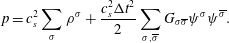 $$\begin{eqnarray}p=c_{s}^{2}\mathop{\sum }_{\unicode[STIX]{x1D70E}}\unicode[STIX]{x1D70C}^{\unicode[STIX]{x1D70E}}+\frac{c_{s}^{2}\unicode[STIX]{x0394}t^{2}}{2}\mathop{\sum }_{\unicode[STIX]{x1D70E},\overline{\unicode[STIX]{x1D70E}}}G_{\unicode[STIX]{x1D70E}\overline{\unicode[STIX]{x1D70E}}}\unicode[STIX]{x1D713}^{\unicode[STIX]{x1D70E}}\unicode[STIX]{x1D713}^{\overline{\unicode[STIX]{x1D70E}}}.\end{eqnarray}$$
Lastly, the interfacial tension
 $\unicode[STIX]{x1D6FE}$
can be calculated using the Laplace law
$\unicode[STIX]{x1D6FE}$
can be calculated using the Laplace law
 $\unicode[STIX]{x0394}p=2\unicode[STIX]{x1D6FE}/r$
, where
$\unicode[STIX]{x0394}p=2\unicode[STIX]{x1D6FE}/r$
, where
 $\unicode[STIX]{x0394}p$
is the pressure difference across the interface of a spherical droplet.
$\unicode[STIX]{x0394}p$
is the pressure difference across the interface of a spherical droplet.
The simulations here have been performed on a
 $D3Q19$
lattice, i.e. a three-dimensional lattice with a set of
$D3Q19$
lattice, i.e. a three-dimensional lattice with a set of
 $19$
discrete velocity directions. Further, the lattice spacing
$19$
discrete velocity directions. Further, the lattice spacing
 $\unicode[STIX]{x0394}x$
and time step
$\unicode[STIX]{x0394}x$
and time step
 $\unicode[STIX]{x0394}t$
are both set equal to
$\unicode[STIX]{x0394}t$
are both set equal to
 $1$
, and consequently all quantities are expressed in dimensionless lattice units [lu].
$1$
, and consequently all quantities are expressed in dimensionless lattice units [lu].
2.2 Turbulence forcing
To generate and sustain turbulence in the fluid, a constant source of energy is required, which is constantly being dissipated by viscosity at the smallest scales (i.e. the Kolmogorov scales). This is done by setting the largest scales of flow into motion, and if the fluid viscosity is low enough, these large structures become unstable and give rise to successively smaller scales. One of the ways to achieve this numerically is by employing a low-wavenumber spectral forcing, as given by Alvelius (Reference Alvelius1999), while alternative techniques could also be used (Eswaran & Pope Reference Eswaran and Pope1988; Rosales & Meneveau Reference Rosales and Meneveau2005). This forcing was also implemented by Ten Cate et al. (Reference Ten Cate, Derksen, Portela and Van den Akker2004) in LB to simulate the response of clouds of spherical solid particles to homogeneous isotropic turbulence. A very similar form of the forcing is used by Perlekar et al. (Reference Perlekar, Biferale, Sbragaglia, Srivastava and Toschi2012), which is constructed directly in real space but could be made to have a similar effective spectral form as Ten Cate et al. (Reference Ten Cate, Derksen, Portela and Van den Akker2004, Reference Ten Cate, Van Vliet, Derksen and Van den Akker2006), albeit with less control over output parameters, as we do in this study. The forcing is divergence free by construction and can be written as
 $$\begin{eqnarray}\left.\begin{array}{@{}c@{}}\displaystyle F_{x}^{\unicode[STIX]{x1D70E}}=\mathop{\sum }_{k=k_{a}}^{k_{b}}\frac{\unicode[STIX]{x1D70C}^{\unicode[STIX]{x1D70E}}}{\unicode[STIX]{x1D70C}^{tot}}A(k)[\sin (2\unicode[STIX]{x03C0}ky+\unicode[STIX]{x1D719}_{y}(k))+\sin (2\unicode[STIX]{x03C0}kz+\unicode[STIX]{x1D719}_{z}(k))],\\ \displaystyle F_{y}^{\unicode[STIX]{x1D70E}}=\mathop{\sum }_{k=k_{a}}^{k_{b}}\frac{\unicode[STIX]{x1D70C}^{\unicode[STIX]{x1D70E}}}{\unicode[STIX]{x1D70C}^{tot}}A(k)[\sin (2\unicode[STIX]{x03C0}kx+\unicode[STIX]{x1D719}_{x}(k))+\sin (2\unicode[STIX]{x03C0}kz+\unicode[STIX]{x1D719}_{z}(k))],\\ \displaystyle F_{z}^{\unicode[STIX]{x1D70E}}=\mathop{\sum }_{k=k_{a}}^{k_{b}}\frac{\unicode[STIX]{x1D70C}^{\unicode[STIX]{x1D70E}}}{\unicode[STIX]{x1D70C}^{tot}}A(k)[\sin (2\unicode[STIX]{x03C0}kx+\unicode[STIX]{x1D719}_{x}(k))+\sin (2\unicode[STIX]{x03C0}ky+\unicode[STIX]{x1D719}_{y}(k))].\end{array}\right\}\end{eqnarray}$$
Here each
 $\unicode[STIX]{x1D719}_{i}(k)$
is a unique random phase. Alternatively,
$\unicode[STIX]{x1D719}_{i}(k)$
is a unique random phase. Alternatively,
 $\unicode[STIX]{x1D719}_{i}(k)$
can be evolved as a stochastic process, as done in Perlekar et al. (Reference Perlekar, Biferale, Sbragaglia, Srivastava and Toschi2012), but in our approach
$\unicode[STIX]{x1D719}_{i}(k)$
can be evolved as a stochastic process, as done in Perlekar et al. (Reference Perlekar, Biferale, Sbragaglia, Srivastava and Toschi2012), but in our approach
 $\unicode[STIX]{x1D719}_{i}(k)$
(and hence the forcing) varies as white noise in time. This ensures that the force is not related to any timescale of turbulent motion, and is a choice also made in Ten Cate et al. (Reference Ten Cate, Van Vliet, Derksen and Van den Akker2006). The force is distributed over a small range of wavenumbers
$\unicode[STIX]{x1D719}_{i}(k)$
(and hence the forcing) varies as white noise in time. This ensures that the force is not related to any timescale of turbulent motion, and is a choice also made in Ten Cate et al. (Reference Ten Cate, Van Vliet, Derksen and Van den Akker2006). The force is distributed over a small range of wavenumbers
 $k_{a}\leqslant k\leqslant k_{b}$
, while the contribution of each of these wavenumbers is determined by
$k_{a}\leqslant k\leqslant k_{b}$
, while the contribution of each of these wavenumbers is determined by
 $A(k)$
, which centres the Gaussian around
$A(k)$
, which centres the Gaussian around
 $k_{f}$
in Fourier space, given as
$k_{f}$
in Fourier space, given as
 $$\begin{eqnarray}A(k)=A\exp \left(-\frac{(k-k_{f})^{2}}{c}\right),\end{eqnarray}$$
where
 $k_{f}$
is the central forcing wavenumber,
$k_{f}$
is the central forcing wavenumber,
 $c$
is a width over which to distribute the force amplitude and is set to
$c$
is a width over which to distribute the force amplitude and is set to
 $c=1.25$
, and
$c=1.25$
, and
 $A$
is a forcing magnitude. This method ensures that there is a dominant central wavenumber
$A$
is a forcing magnitude. This method ensures that there is a dominant central wavenumber
 $k_{f}$
(which can also be a fraction) in the forcing scheme, while neighbouring wavenumbers also contain some energy, which makes the scheme more stable (Ten Cate et al.
Reference Ten Cate, Van Vliet, Derksen and Van den Akker2006). Lastly, the total power input to the fluid can be written as the sum of two terms as follows:
$k_{f}$
(which can also be a fraction) in the forcing scheme, while neighbouring wavenumbers also contain some energy, which makes the scheme more stable (Ten Cate et al.
Reference Ten Cate, Van Vliet, Derksen and Van den Akker2006). Lastly, the total power input to the fluid can be written as the sum of two terms as follows:
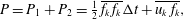 $$\begin{eqnarray}P=P_{1}+P_{2}={\textstyle \frac{1}{2}}\,\overline{f_{k}\,f_{k}}\unicode[STIX]{x0394}t+\overline{u_{k}\,f_{k}},\end{eqnarray}$$
where the two terms are the force–force and force–velocity correlations respectively, and
 $u_{k},f_{k}$
refer to the volumetric velocity and force fields. The force–velocity correlation,
$u_{k},f_{k}$
refer to the volumetric velocity and force fields. The force–velocity correlation,
 $P_{2}$
, should be
$P_{2}$
, should be
 $0$
to avoid an uncontrolled growth of energy in the fluid (Alvelius Reference Alvelius1999), and it is achieved by varying the force term at each time step. This is computationally expensive, hence some studies (Ten Cate et al.
Reference Ten Cate, Derksen, Portela and Van den Akker2004, Reference Ten Cate, Van Vliet, Derksen and Van den Akker2006) vary the force by choosing randomly from a pre-computed set of force fields at each time step. This was found to introduce a non-zero contribution from the
$0$
to avoid an uncontrolled growth of energy in the fluid (Alvelius Reference Alvelius1999), and it is achieved by varying the force term at each time step. This is computationally expensive, hence some studies (Ten Cate et al.
Reference Ten Cate, Derksen, Portela and Van den Akker2004, Reference Ten Cate, Van Vliet, Derksen and Van den Akker2006) vary the force by choosing randomly from a pre-computed set of force fields at each time step. This was found to introduce a non-zero contribution from the
 $P_{2}$
term, where the steady-state kinetic energy was roughly
$P_{2}$
term, where the steady-state kinetic energy was roughly
 $10$
times larger than with a unique random force at each time step – hence in this study we adhere to the latter approach.
$10$
times larger than with a unique random force at each time step – hence in this study we adhere to the latter approach.
In the continuum (long-wavelength) limit, the PP-LB model solves the Navier–Stokes equations for the two-fluid mixture with a body force (see Scarbolo et al. Reference Scarbolo, Molin, Perlekar, Sbragaglia, Soldati and Toschi2013)
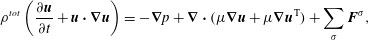 $$\begin{eqnarray}\unicode[STIX]{x1D70C}^{tot}\left(\frac{\unicode[STIX]{x2202}\boldsymbol{u}}{\unicode[STIX]{x2202}t}+\boldsymbol{u}\boldsymbol{\cdot }\unicode[STIX]{x1D735}\boldsymbol{u}\right)=-\unicode[STIX]{x1D735}p+\unicode[STIX]{x1D735}\boldsymbol{\cdot }(\unicode[STIX]{x1D707}\unicode[STIX]{x1D735}\boldsymbol{u}+\unicode[STIX]{x1D707}\unicode[STIX]{x1D735}\boldsymbol{u}^{\text{T}})+\mathop{\sum }_{\unicode[STIX]{x1D70E}}\boldsymbol{F}^{\unicode[STIX]{x1D70E}},\end{eqnarray}$$
where
 $p$
is the pressure (refer to (2.7)),
$p$
is the pressure (refer to (2.7)),
 $\unicode[STIX]{x1D707}=\sum _{\unicode[STIX]{x1D70E}}\unicode[STIX]{x1D70C}^{\unicode[STIX]{x1D70E}}\unicode[STIX]{x1D708}^{\unicode[STIX]{x1D70E}}$
is the dynamic viscosity and
$\unicode[STIX]{x1D707}=\sum _{\unicode[STIX]{x1D70E}}\unicode[STIX]{x1D70C}^{\unicode[STIX]{x1D70E}}\unicode[STIX]{x1D708}^{\unicode[STIX]{x1D70E}}$
is the dynamic viscosity and
 $\boldsymbol{F}^{\unicode[STIX]{x1D70E}}$
is the total force acting on component
$\boldsymbol{F}^{\unicode[STIX]{x1D70E}}$
is the total force acting on component
 $\unicode[STIX]{x1D70E}$
, which here is given as
$\unicode[STIX]{x1D70E}$
, which here is given as
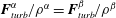
 $\boldsymbol{F}^{\unicode[STIX]{x1D70E}}=\boldsymbol{F}_{PP}^{\unicode[STIX]{x1D70E}}+\boldsymbol{F}_{turb}^{\unicode[STIX]{x1D70E}}$
(i.e. the sum of the pseudopotential contribution as given by (2.6) and the turbulence contribution given by (2.8)). The per component continuity equation includes an additional term, i.e. the divergence of the diffusive current
$\boldsymbol{F}^{\unicode[STIX]{x1D70E}}=\boldsymbol{F}_{PP}^{\unicode[STIX]{x1D70E}}+\boldsymbol{F}_{turb}^{\unicode[STIX]{x1D70E}}$
(i.e. the sum of the pseudopotential contribution as given by (2.6) and the turbulence contribution given by (2.8)). The per component continuity equation includes an additional term, i.e. the divergence of the diffusive current
 $\boldsymbol{J}^{\unicode[STIX]{x1D70E}}$
(as given in Scarbolo et al. (Reference Scarbolo, Molin, Perlekar, Sbragaglia, Soldati and Toschi2013)) which causes phase segregation between the two components, and has the form
$\boldsymbol{J}^{\unicode[STIX]{x1D70E}}$
(as given in Scarbolo et al. (Reference Scarbolo, Molin, Perlekar, Sbragaglia, Soldati and Toschi2013)) which causes phase segregation between the two components, and has the form
 $$\begin{eqnarray}\frac{\unicode[STIX]{x2202}\unicode[STIX]{x1D70C}^{\unicode[STIX]{x1D70E}}}{\unicode[STIX]{x2202}t}+\unicode[STIX]{x1D735}\boldsymbol{\cdot }(\unicode[STIX]{x1D70C}^{\unicode[STIX]{x1D70E}}\boldsymbol{u})=\unicode[STIX]{x1D735}\boldsymbol{\cdot }\boldsymbol{J}^{\unicode[STIX]{x1D70E}},\end{eqnarray}$$
where
 $$\begin{eqnarray}\boldsymbol{J}^{\unicode[STIX]{x1D6FC}}=\frac{\unicode[STIX]{x1D70C}^{\unicode[STIX]{x1D6FC}}\unicode[STIX]{x1D70C}^{\unicode[STIX]{x1D6FD}}}{\unicode[STIX]{x1D70C}^{tot}}\left[c_{s}^{2}\left(\unicode[STIX]{x1D70F}-\frac{1}{2}\right)\left(\frac{\unicode[STIX]{x1D735}\unicode[STIX]{x1D70C}^{\unicode[STIX]{x1D6FC}}}{\unicode[STIX]{x1D70C}^{\unicode[STIX]{x1D6FC}}}-\frac{\unicode[STIX]{x1D735}\unicode[STIX]{x1D70C}^{\unicode[STIX]{x1D6FD}}}{\unicode[STIX]{x1D70C}^{\unicode[STIX]{x1D6FD}}}\right)-\unicode[STIX]{x1D70F}\left(\frac{\boldsymbol{F}^{\unicode[STIX]{x1D6FC}}}{\unicode[STIX]{x1D70C}^{\unicode[STIX]{x1D6FC}}}-\frac{\boldsymbol{F}^{\unicode[STIX]{x1D6FD}}}{\unicode[STIX]{x1D70C}^{\unicode[STIX]{x1D6FD}}}\right)\right]=-\boldsymbol{J}^{\unicode[STIX]{x1D6FD}}.\end{eqnarray}$$
It can be seen that the turbulence force contribution to
 $\boldsymbol{J}^{\unicode[STIX]{x1D70E}}$
cancels out since
$\boldsymbol{J}^{\unicode[STIX]{x1D70E}}$
cancels out since
 $\boldsymbol{F}_{turb}^{\unicode[STIX]{x1D6FC}}/\unicode[STIX]{x1D70C}^{\unicode[STIX]{x1D6FC}}=\boldsymbol{F}_{turb}^{\unicode[STIX]{x1D6FD}}/\unicode[STIX]{x1D70C}^{\unicode[STIX]{x1D6FD}}$
. Further, the flux of each component is negligible away from interfaces where gradients of density and the pseudopotential force vanish. The global continuity equation, obtained by adding individual component continuity equations, is not influenced by the diffusive current term (since
$\boldsymbol{F}_{turb}^{\unicode[STIX]{x1D6FC}}/\unicode[STIX]{x1D70C}^{\unicode[STIX]{x1D6FC}}=\boldsymbol{F}_{turb}^{\unicode[STIX]{x1D6FD}}/\unicode[STIX]{x1D70C}^{\unicode[STIX]{x1D6FD}}$
. Further, the flux of each component is negligible away from interfaces where gradients of density and the pseudopotential force vanish. The global continuity equation, obtained by adding individual component continuity equations, is not influenced by the diffusive current term (since
 $\boldsymbol{J}^{\unicode[STIX]{x1D6FC}}=-\boldsymbol{J}^{\unicode[STIX]{x1D6FD}}$
). For more details on the continuum form of the equations, refer to Shan & Doolen (Reference Shan and Doolen1995), Scarbolo et al. (Reference Scarbolo, Molin, Perlekar, Sbragaglia, Soldati and Toschi2013) and chap. 4 of Krüger et al. (Reference Krüger, Kusumaatmaja, Kuzmin, Shardt, Silva and Viggen2017).
$\boldsymbol{J}^{\unicode[STIX]{x1D6FC}}=-\boldsymbol{J}^{\unicode[STIX]{x1D6FD}}$
). For more details on the continuum form of the equations, refer to Shan & Doolen (Reference Shan and Doolen1995), Scarbolo et al. (Reference Scarbolo, Molin, Perlekar, Sbragaglia, Soldati and Toschi2013) and chap. 4 of Krüger et al. (Reference Krüger, Kusumaatmaja, Kuzmin, Shardt, Silva and Viggen2017).
2.3 Turbulence quantities
The largest scale in the system is given by the domain size
 $N_{x}$
, which sets the minimum wavenumber
$N_{x}$
, which sets the minimum wavenumber
 $k_{min}=2\unicode[STIX]{x03C0}/N_{x}$
. All other wavenumbers are integer multiples of
$k_{min}=2\unicode[STIX]{x03C0}/N_{x}$
. All other wavenumbers are integer multiples of
 $k_{min}$
, with the maximum wavenumber being
$k_{min}$
, with the maximum wavenumber being
 $k_{max}=k_{min}N_{x}/2=\unicode[STIX]{x03C0}$
. The smallest scale of turbulence (Kolmogorov scale) is calculated as
$k_{max}=k_{min}N_{x}/2=\unicode[STIX]{x03C0}$
. The smallest scale of turbulence (Kolmogorov scale) is calculated as
 $\unicode[STIX]{x1D702}\sim (\unicode[STIX]{x1D708}^{3}/\unicode[STIX]{x1D716})^{1/4}$
where
$\unicode[STIX]{x1D702}\sim (\unicode[STIX]{x1D708}^{3}/\unicode[STIX]{x1D716})^{1/4}$
where
 $\unicode[STIX]{x1D708}$
and
$\unicode[STIX]{x1D708}$
and
 $\unicode[STIX]{x1D716}$
are the kinematic viscosity and energy dissipation rate respectively. The criterion for a resolved DNS is that
$\unicode[STIX]{x1D716}$
are the kinematic viscosity and energy dissipation rate respectively. The criterion for a resolved DNS is that
 $k_{max}\unicode[STIX]{x1D702}>1$
(Moin & Mahesh Reference Moin and Mahesh1998), and the Kolmogorov scale should obey
$k_{max}\unicode[STIX]{x1D702}>1$
(Moin & Mahesh Reference Moin and Mahesh1998), and the Kolmogorov scale should obey
 $\unicode[STIX]{x1D702}>0.318$
[lu] (Ten Cate et al.
Reference Ten Cate, Van Vliet, Derksen and Van den Akker2006). We shall mention the forcing wavenumber
$\unicode[STIX]{x1D702}>0.318$
[lu] (Ten Cate et al.
Reference Ten Cate, Van Vliet, Derksen and Van den Akker2006). We shall mention the forcing wavenumber
 $k_{f}$
and the wavenumber bounds as multiples of
$k_{f}$
and the wavenumber bounds as multiples of
 $k_{min}$
in this study. For a central forcing wavenumber
$k_{min}$
in this study. For a central forcing wavenumber
 $k_{f}$
, the associated large scale length then becomes
$k_{f}$
, the associated large scale length then becomes
 $$\begin{eqnarray}{\mathcal{L}}\sim \frac{2\unicode[STIX]{x03C0}}{k_{f}k_{min}}=\frac{N_{x}}{k_{f}}.\end{eqnarray}$$
Further, the Taylor microscale is calculated as
 $$\begin{eqnarray}\unicode[STIX]{x1D706}=\left(\frac{15\unicode[STIX]{x1D708}{u^{\prime }}^{2}}{\unicode[STIX]{x1D716}}\right)^{1/2},\end{eqnarray}$$
where
 $u^{\prime }$
is the root mean square velocity along one direction, and
$u^{\prime }$
is the root mean square velocity along one direction, and
 $u_{x}^{\prime }=u_{y}^{\prime }=u_{z}^{\prime }$
in isotropic turbulence. The rate of energy dissipation
$u_{x}^{\prime }=u_{y}^{\prime }=u_{z}^{\prime }$
in isotropic turbulence. The rate of energy dissipation
 $\langle \unicode[STIX]{x1D716}\rangle$
can be found in two ways, as
$\langle \unicode[STIX]{x1D716}\rangle$
can be found in two ways, as
 $\unicode[STIX]{x1D716}\approx \unicode[STIX]{x1D708}\langle \unicode[STIX]{x1D714}^{2}\rangle \approx \sum _{k}2\unicode[STIX]{x1D708}k^{2}E(k)/N_{x}^{3}$
where
$\unicode[STIX]{x1D716}\approx \unicode[STIX]{x1D708}\langle \unicode[STIX]{x1D714}^{2}\rangle \approx \sum _{k}2\unicode[STIX]{x1D708}k^{2}E(k)/N_{x}^{3}$
where
 $\langle \unicode[STIX]{x1D714}^{2}\rangle$
is the average enstrophy and
$\langle \unicode[STIX]{x1D714}^{2}\rangle$
is the average enstrophy and
 $E(k)$
is the kinetic energy spectrum. Using
$E(k)$
is the kinetic energy spectrum. Using
 $\unicode[STIX]{x1D706}$
, the Taylor Reynolds number is calculated as
$\unicode[STIX]{x1D706}$
, the Taylor Reynolds number is calculated as
 $$\begin{eqnarray}Re_{\unicode[STIX]{x1D706}}=\frac{u^{\prime }\unicode[STIX]{x1D706}}{\unicode[STIX]{x1D708}}.\end{eqnarray}$$
Lastly, the Kolmogorov timescale is given as
 $$\begin{eqnarray}\unicode[STIX]{x1D70F}_{k}=\left(\frac{\unicode[STIX]{x1D716}}{\unicode[STIX]{x1D708}}\right)^{-1/2}.\end{eqnarray}$$
For eddies in the inertial range with a size
 $l$
, the velocity
$l$
, the velocity
 $u(l)$
and timescale
$u(l)$
and timescale
 $\unicode[STIX]{x1D70F}(l)$
are determined uniquely by
$\unicode[STIX]{x1D70F}(l)$
are determined uniquely by
 $\unicode[STIX]{x1D716}$
and
$\unicode[STIX]{x1D716}$
and
 $l$
alone as
$l$
alone as
 $u(l)=(\unicode[STIX]{x1D716}l)^{1/3}\sim {\mathcal{U}}(l/{\mathcal{L}})^{1/3}$
and
$u(l)=(\unicode[STIX]{x1D716}l)^{1/3}\sim {\mathcal{U}}(l/{\mathcal{L}})^{1/3}$
and
 $\unicode[STIX]{x1D70F}(l)=(l^{2}/\unicode[STIX]{x1D716})^{1/3}\sim {\mathcal{T}}(l/{\mathcal{L}})^{2/3}$
, where
$\unicode[STIX]{x1D70F}(l)=(l^{2}/\unicode[STIX]{x1D716})^{1/3}\sim {\mathcal{T}}(l/{\mathcal{L}})^{2/3}$
, where
 ${\mathcal{L}}$
,
${\mathcal{L}}$
,
 ${\mathcal{T}}$
and
${\mathcal{T}}$
and
 ${\mathcal{U}}$
are the characteristic length, time and velocity of the largest eddies (with
${\mathcal{U}}$
are the characteristic length, time and velocity of the largest eddies (with
 ${\mathcal{T}}={\mathcal{L}}/{\mathcal{U}}$
). We consider
${\mathcal{T}}={\mathcal{L}}/{\mathcal{U}}$
). We consider
 ${\mathcal{U}}\approx \langle E_{k}\rangle ^{1/2}$
as the largest eddies contain most of the kinetic energy, and generally
${\mathcal{U}}\approx \langle E_{k}\rangle ^{1/2}$
as the largest eddies contain most of the kinetic energy, and generally
 $u^{\prime }<{\mathcal{U}}$
. The characteristic velocity at a particular lengthscale can also be found from the kinetic energy spectrum as
$u^{\prime }<{\mathcal{U}}$
. The characteristic velocity at a particular lengthscale can also be found from the kinetic energy spectrum as
 $u(l)\approx \sqrt{E(k_{l})}$
where
$u(l)\approx \sqrt{E(k_{l})}$
where
 $k_{l}=2\unicode[STIX]{x03C0}/l$
.
$k_{l}=2\unicode[STIX]{x03C0}/l$
.
3 Single-phase turbulence
We begin with a single-phase turbulence simulation to show that the forcing scheme is able to maintain a statistically stationary turbulent flow (simulation ‘SP’ in table 1) and to compare it with results available in the literature. A domain of
 $256^{3}$
lattice nodes representing a length
$256^{3}$
lattice nodes representing a length
 $(2\unicode[STIX]{x03C0})^{3}$
is initialized with a uniform initial density of
$(2\unicode[STIX]{x03C0})^{3}$
is initialized with a uniform initial density of
 $\unicode[STIX]{x1D70C}^{\unicode[STIX]{x1D6FC}}=4.0$
[lu]. The relaxation time is set to
$\unicode[STIX]{x1D70C}^{\unicode[STIX]{x1D6FC}}=4.0$
[lu]. The relaxation time is set to
 $\unicode[STIX]{x1D70F}=0.5141$
which gives a viscosity of
$\unicode[STIX]{x1D70F}=0.5141$
which gives a viscosity of
 $\unicode[STIX]{x1D708}=0.0047$
[lu] (Perlekar et al. (Reference Perlekar, Biferale, Sbragaglia, Srivastava and Toschi2012) use a similar value with
$\unicode[STIX]{x1D708}=0.0047$
[lu] (Perlekar et al. (Reference Perlekar, Biferale, Sbragaglia, Srivastava and Toschi2012) use a similar value with
 $\unicode[STIX]{x1D70F}=0.515$
), which is a low enough viscosity to sustain turbulence while still being numerically stable. The forcing is concentrated around
$\unicode[STIX]{x1D70F}=0.515$
), which is a low enough viscosity to sustain turbulence while still being numerically stable. The forcing is concentrated around
 $k_{f}=2k_{min}$
and is distributed in the range of
$k_{f}=2k_{min}$
and is distributed in the range of
 $k=k_{min}$
to
$k=k_{min}$
to
 $8k_{min}$
, and is applied from
$8k_{min}$
, and is applied from
 $t=0$
to a fluid initially at rest, i.e. with zero velocity. Further,
$t=0$
to a fluid initially at rest, i.e. with zero velocity. Further,
 $A=0.0005$
, which generates a turbulent flow with a Taylor microscale of
$A=0.0005$
, which generates a turbulent flow with a Taylor microscale of
 $\unicode[STIX]{x1D706}=13~[\text{lu}]$
,
$\unicode[STIX]{x1D706}=13~[\text{lu}]$
,
 $Re_{\unicode[STIX]{x1D706}}=95$
,
$Re_{\unicode[STIX]{x1D706}}=95$
,
 $\unicode[STIX]{x1D70F}_{k}=97~[\text{lu}]$
,
$\unicode[STIX]{x1D70F}_{k}=97~[\text{lu}]$
,
 $\unicode[STIX]{x1D702}=0.7~[\text{lu}]$
(
$\unicode[STIX]{x1D702}=0.7~[\text{lu}]$
(
 $k_{max}\unicode[STIX]{x1D702}=2.2$
) and
$k_{max}\unicode[STIX]{x1D702}=2.2$
) and
 $\langle \unicode[STIX]{x1D716}\rangle \approx 5\times 10^{-7}~[\text{lu}]$
, which are calculated a posteriori. The simulation is performed for
$\langle \unicode[STIX]{x1D716}\rangle \approx 5\times 10^{-7}~[\text{lu}]$
, which are calculated a posteriori. The simulation is performed for
 $10^{5}\unicode[STIX]{x0394}t$
, which corresponds to
$10^{5}\unicode[STIX]{x0394}t$
, which corresponds to
 $1000\unicode[STIX]{x1D70F}_{k}$
.
$1000\unicode[STIX]{x1D70F}_{k}$
.
Figure 1 shows the evolution of
 $\langle E_{k}\rangle$
and
$\langle E_{k}\rangle$
and
 $\langle \unicode[STIX]{x1D714}^{2}\rangle$
which attain their steady-state values around
$\langle \unicode[STIX]{x1D714}^{2}\rangle$
which attain their steady-state values around
 $75\unicode[STIX]{x1D70F}_{k}$
and continue to oscillate around this value. Note that the turbulence forcing scheme is steady in the sense that it leads to the balance of energy injection and dissipation. The large-scale instability itself is not steady, and the force variation in time leads to intermittency of the power input which is a standard feature of continuously forced turbulence (Alvelius Reference Alvelius1999; Rosales & Meneveau Reference Rosales and Meneveau2005). Further in figure 1 (see inset), the crests and troughs of the
$75\unicode[STIX]{x1D70F}_{k}$
and continue to oscillate around this value. Note that the turbulence forcing scheme is steady in the sense that it leads to the balance of energy injection and dissipation. The large-scale instability itself is not steady, and the force variation in time leads to intermittency of the power input which is a standard feature of continuously forced turbulence (Alvelius Reference Alvelius1999; Rosales & Meneveau Reference Rosales and Meneveau2005). Further in figure 1 (see inset), the crests and troughs of the
 $\langle E_{k}\rangle$
evolution show up in the
$\langle E_{k}\rangle$
evolution show up in the
 $\langle \unicode[STIX]{x1D714}^{2}\rangle$
evolution with a slight delay, where the quantities have been normalized with their time-averaged values over the latter
$\langle \unicode[STIX]{x1D714}^{2}\rangle$
evolution with a slight delay, where the quantities have been normalized with their time-averaged values over the latter
 $3/4$
of the simulation duration. This has been observed before, and ascribed to the energy cascading mechanism (Pearson et al.
Reference Pearson, Yousef, Haugen, Brandenburg and Krogstad2004; Biferale et al.
Reference Biferale, Perlekar, Sbragaglia, Srivastava and Toschi2011) while Tsinober (Reference Tsinober2009) acknowledges this feature without invoking a cascade.
$3/4$
of the simulation duration. This has been observed before, and ascribed to the energy cascading mechanism (Pearson et al.
Reference Pearson, Yousef, Haugen, Brandenburg and Krogstad2004; Biferale et al.
Reference Biferale, Perlekar, Sbragaglia, Srivastava and Toschi2011) while Tsinober (Reference Tsinober2009) acknowledges this feature without invoking a cascade.
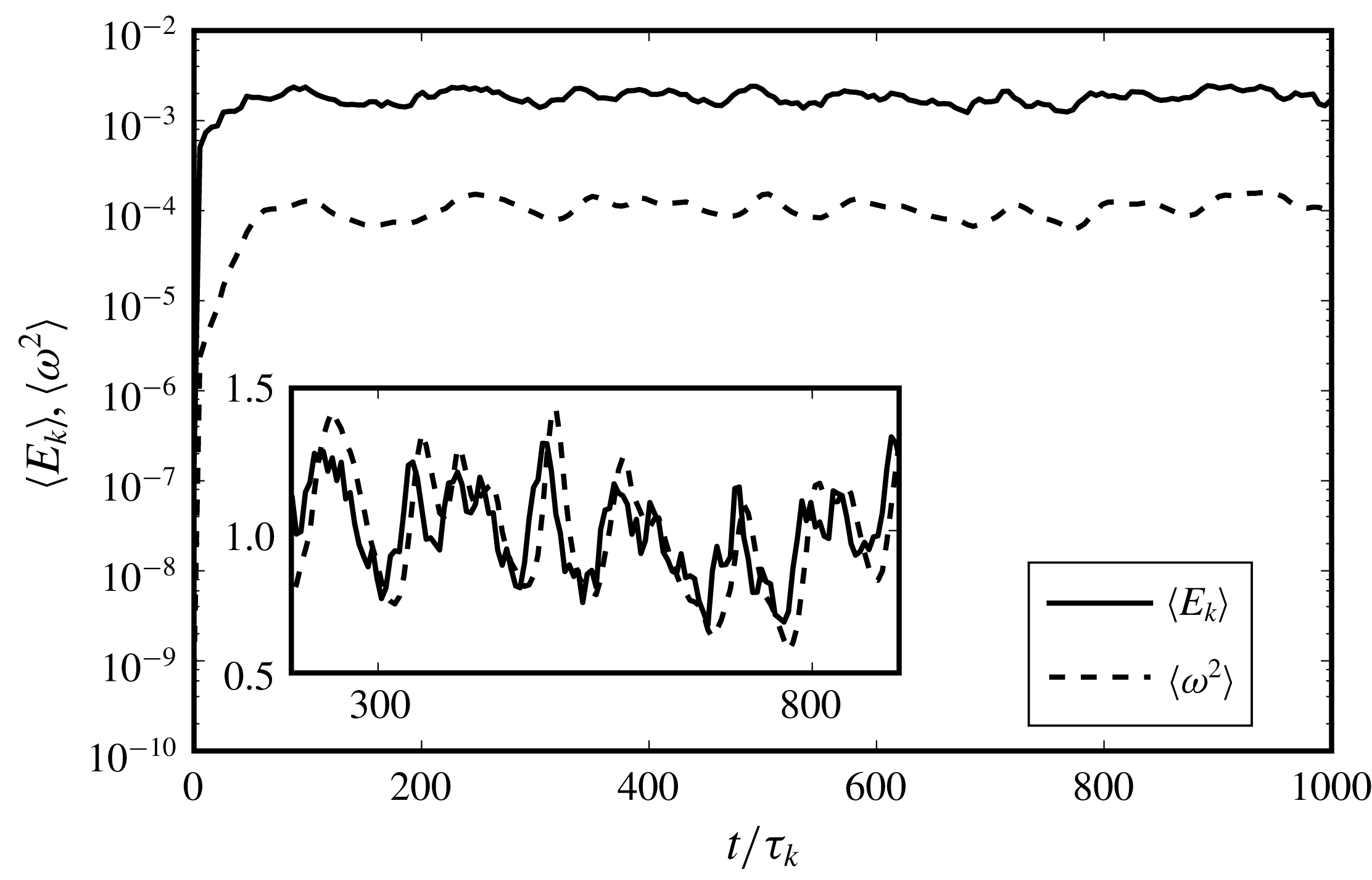
Figure 1. Evolution of average kinetic energy
 $\langle E_{k}\rangle$
and enstrophy
$\langle E_{k}\rangle$
and enstrophy
 $\langle \unicode[STIX]{x1D714}^{2}\rangle$
in the single-phase turbulence simulation with
$\langle \unicode[STIX]{x1D714}^{2}\rangle$
in the single-phase turbulence simulation with
 $Re_{\unicode[STIX]{x1D706}}=95$
. Both
$Re_{\unicode[STIX]{x1D706}}=95$
. Both
 $\langle E_{k}\rangle$
and
$\langle E_{k}\rangle$
and
 $\langle \unicode[STIX]{x1D714}^{2}\rangle$
reach steady state, confirming the balance between the energy dissipation and power input. In the inset, both profiles have been normalized by their time-averaged value over the latter
$\langle \unicode[STIX]{x1D714}^{2}\rangle$
reach steady state, confirming the balance between the energy dissipation and power input. In the inset, both profiles have been normalized by their time-averaged value over the latter
 $3/4$
of the simulation duration.
$3/4$
of the simulation duration.
Figure 2 shows typical velocity and enstrophy field snapshots from a planar cross-section in the centre of the domain at
 $500\unicode[STIX]{x1D70F}_{k}$
. The velocity field shows motions across various scales, while the enstrophy field (which is the square of the vorticity) shows typical small-scale localized structures. Also note that
$500\unicode[STIX]{x1D70F}_{k}$
. The velocity field shows motions across various scales, while the enstrophy field (which is the square of the vorticity) shows typical small-scale localized structures. Also note that
 $\unicode[STIX]{x1D714}^{2}$
assumes values as much as
$\unicode[STIX]{x1D714}^{2}$
assumes values as much as
 $10$
times the average
$10$
times the average
 $\langle \unicode[STIX]{x1D714}^{2}\rangle$
(while at higher
$\langle \unicode[STIX]{x1D714}^{2}\rangle$
(while at higher
 $Re_{\unicode[STIX]{x1D706}}$
, more extreme values are found), showing that intermittency is well reproduced in the simulations. This patchy structure of enstrophy is an important factor to consider in simulations of turbulent dispersions, as it leads to varying degrees of droplet–vorticity interactions which can in turn lead to droplet breakup.
$Re_{\unicode[STIX]{x1D706}}$
, more extreme values are found), showing that intermittency is well reproduced in the simulations. This patchy structure of enstrophy is an important factor to consider in simulations of turbulent dispersions, as it leads to varying degrees of droplet–vorticity interactions which can in turn lead to droplet breakup.
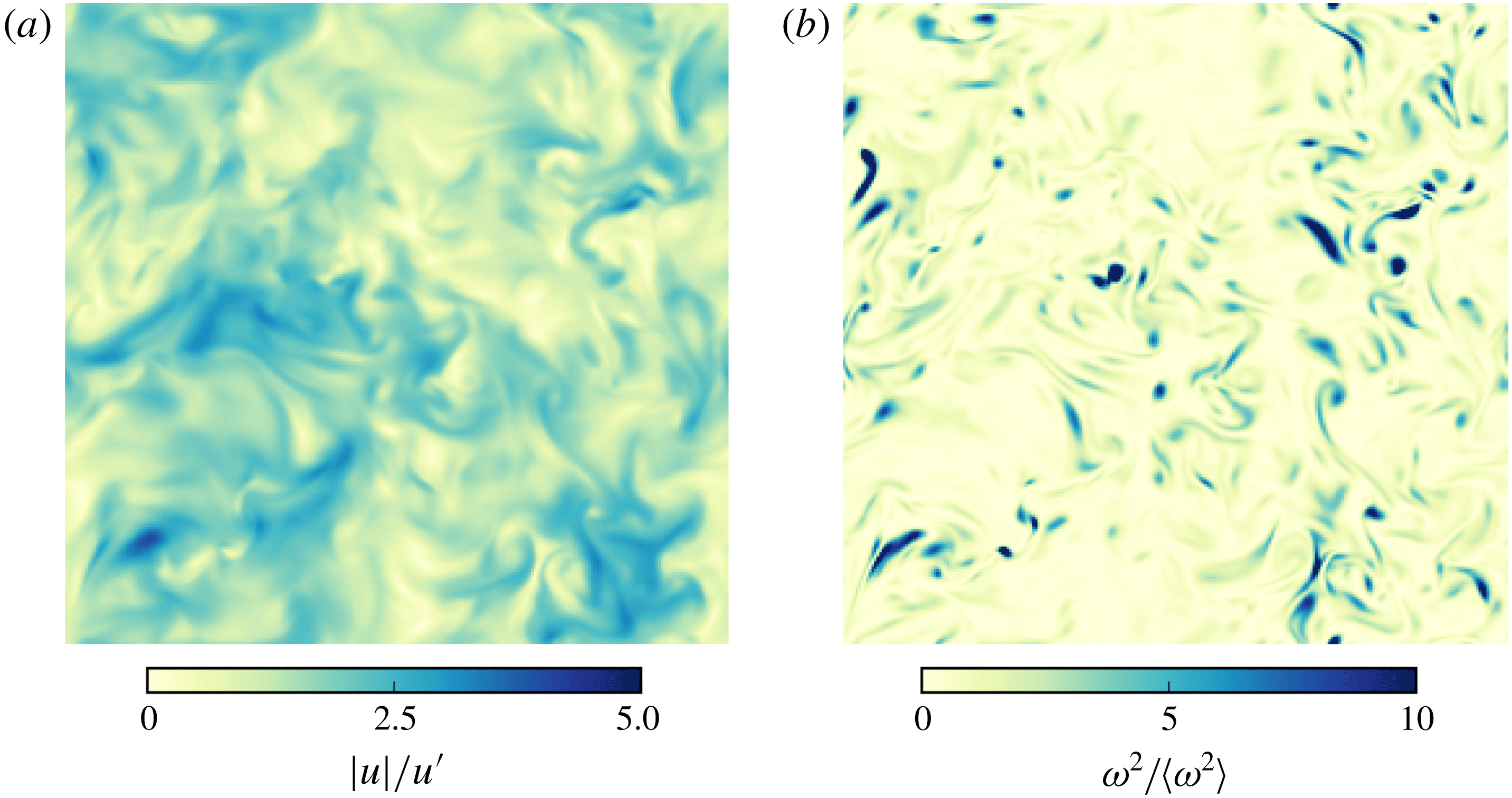
Figure 2. Cross-sections (at
 $z=N_{x}/2$
) show snapshots of the velocity magnitude
$z=N_{x}/2$
) show snapshots of the velocity magnitude
 $|u|$
(a) and enstrophy
$|u|$
(a) and enstrophy
 $\unicode[STIX]{x1D714}^{2}$
(b) at time
$\unicode[STIX]{x1D714}^{2}$
(b) at time
 $t=500\unicode[STIX]{x1D70F}_{k}$
. Features typical of turbulent flow can be seen, where the velocity field shows features across several lengthscales while enstrophy remains localized in small-scale structures.
$t=500\unicode[STIX]{x1D70F}_{k}$
. Features typical of turbulent flow can be seen, where the velocity field shows features across several lengthscales while enstrophy remains localized in small-scale structures.
The kinetic energy spectrum is shown in figure 3, along with a benchmark spectrum from the Johns Hopkins Turbulence Database (Li et al.
Reference Li, Perlman, Wan, Yang, Meneveau, Burns, Chen, Szalay and Eyink2008) for a homogeneous isotropic turbulence simulation with
 $Re_{\unicode[STIX]{x1D706}}=433$
(on a grid of
$Re_{\unicode[STIX]{x1D706}}=433$
(on a grid of
 $1024^{3}$
, generated with a spectral solver). The energy
$1024^{3}$
, generated with a spectral solver). The energy
 $E(k)$
has been normalized by the total energy
$E(k)$
has been normalized by the total energy
 $\sum _{k}E(k)$
, and the wavenumber is normalized to show multiples of
$\sum _{k}E(k)$
, and the wavenumber is normalized to show multiples of
 $k_{min}$
, which is done to compare the two spectra. A well-developed inertial range is seen to exist, following the
$k_{min}$
, which is done to compare the two spectra. A well-developed inertial range is seen to exist, following the
 $k^{-5/3}$
spectral slope, which falls off around
$k^{-5/3}$
spectral slope, which falls off around
 $k=30k_{min}$
in our simulation. Lastly, in this simulation
$k=30k_{min}$
in our simulation. Lastly, in this simulation
 $u^{\prime }=0.034~[\text{lu}]$
, and since the speed of sound is
$u^{\prime }=0.034~[\text{lu}]$
, and since the speed of sound is
 $c_{s}=1/\sqrt{3}~[\text{lu}]$
, the flow Mach number is
$c_{s}=1/\sqrt{3}~[\text{lu}]$
, the flow Mach number is
 $Ma=0.06$
which is well within the incompressibility limit.
$Ma=0.06$
which is well within the incompressibility limit.

Figure 3. Kinetic energy spectrum for the single-phase simulation shown together with a sample spectrum from the Johns Hopkins Turbulence Database (JHTD, with
 $Re_{\unicode[STIX]{x1D706}}=433$
). The chosen normalization is only to compare the shape of the two spectra along with a
$Re_{\unicode[STIX]{x1D706}}=433$
). The chosen normalization is only to compare the shape of the two spectra along with a
 $k^{-5/3}$
inertial range scaling. The spectrum is further averaged over 20 realizations separated by
$k^{-5/3}$
inertial range scaling. The spectrum is further averaged over 20 realizations separated by
 $50\unicode[STIX]{x1D70F}_{k}$
.
$50\unicode[STIX]{x1D70F}_{k}$
.
4 Turbulent emulsions
4.1 Simulation set-up
The turbulent emulsion simulations are initialized with two fluids, which we denote by
 $\unicode[STIX]{x1D6FC}$
(the carrier fluid) and
$\unicode[STIX]{x1D6FC}$
(the carrier fluid) and
 $\unicode[STIX]{x1D6FD}$
(the droplet fluid), with a liquid–liquid density ratio
$\unicode[STIX]{x1D6FD}$
(the droplet fluid), with a liquid–liquid density ratio
 $\unicode[STIX]{x1D70C}_{\unicode[STIX]{x1D6FD}}/\unicode[STIX]{x1D70C}_{\unicode[STIX]{x1D6FC}}=1$
, which well represents many oil-in-water emulsions. For a chosen volume fraction
$\unicode[STIX]{x1D70C}_{\unicode[STIX]{x1D6FD}}/\unicode[STIX]{x1D70C}_{\unicode[STIX]{x1D6FC}}=1$
, which well represents many oil-in-water emulsions. For a chosen volume fraction
 $\unicode[STIX]{x1D719}$
of fluid
$\unicode[STIX]{x1D719}$
of fluid
 $\unicode[STIX]{x1D6FD}$
, a single spherical droplet (a
$\unicode[STIX]{x1D6FD}$
, a single spherical droplet (a
 $\unicode[STIX]{x1D6FD}$
-rich region) is initialized in the centre of the domain, which is otherwise
$\unicode[STIX]{x1D6FD}$
-rich region) is initialized in the centre of the domain, which is otherwise
 $\unicode[STIX]{x1D6FC}$
-rich. The droplet density is denoted by
$\unicode[STIX]{x1D6FC}$
-rich. The droplet density is denoted by
 $\unicode[STIX]{x1D70C}_{\unicode[STIX]{x1D6FD}}^{in}$
, i.e. the density of
$\unicode[STIX]{x1D70C}_{\unicode[STIX]{x1D6FD}}^{in}$
, i.e. the density of
 $\unicode[STIX]{x1D6FD}$
in the
$\unicode[STIX]{x1D6FD}$
in the
 $\unicode[STIX]{x1D6FD}$
-rich region, while
$\unicode[STIX]{x1D6FD}$
-rich region, while
 $\unicode[STIX]{x1D70C}_{\unicode[STIX]{x1D6FD}}^{out}$
denotes the dissolved amount of component
$\unicode[STIX]{x1D70C}_{\unicode[STIX]{x1D6FD}}^{out}$
denotes the dissolved amount of component
 $\unicode[STIX]{x1D6FD}$
in the
$\unicode[STIX]{x1D6FD}$
in the
 $\unicode[STIX]{x1D6FC}$
-rich region (i.e. the continuous phase), and likewise for component
$\unicode[STIX]{x1D6FC}$
-rich region (i.e. the continuous phase), and likewise for component
 $\unicode[STIX]{x1D6FC}$
. Further,
$\unicode[STIX]{x1D6FC}$
. Further,
 $\unicode[STIX]{x1D70C}_{\unicode[STIX]{x1D6FD}}^{avg}$
is used to refer to the average density of component
$\unicode[STIX]{x1D70C}_{\unicode[STIX]{x1D6FD}}^{avg}$
is used to refer to the average density of component
 $\unicode[STIX]{x1D6FD}$
in the entire domain. During the simulation, these density values can change to some extent depending on the
$\unicode[STIX]{x1D6FD}$
in the entire domain. During the simulation, these density values can change to some extent depending on the
 $G_{\unicode[STIX]{x1D6FC}\unicode[STIX]{x1D6FD}}$
parameter, though due to the symmetry of the model we have
$G_{\unicode[STIX]{x1D6FC}\unicode[STIX]{x1D6FD}}$
parameter, though due to the symmetry of the model we have
 $\unicode[STIX]{x1D70C}_{\unicode[STIX]{x1D6FD}}^{in}/\unicode[STIX]{x1D70C}_{\unicode[STIX]{x1D6FC}}^{in}=1$
and
$\unicode[STIX]{x1D70C}_{\unicode[STIX]{x1D6FD}}^{in}/\unicode[STIX]{x1D70C}_{\unicode[STIX]{x1D6FC}}^{in}=1$
and
 $\unicode[STIX]{x1D70C}_{\unicode[STIX]{x1D6FD}}^{out}/\unicode[STIX]{x1D70C}_{\unicode[STIX]{x1D6FC}}^{out}=1$
. We also keep
$\unicode[STIX]{x1D70C}_{\unicode[STIX]{x1D6FD}}^{out}/\unicode[STIX]{x1D70C}_{\unicode[STIX]{x1D6FC}}^{out}=1$
. We also keep
 $\unicode[STIX]{x1D708}_{\unicode[STIX]{x1D6FD}}/\unicode[STIX]{x1D708}_{\unicode[STIX]{x1D6FC}}=1$
(with
$\unicode[STIX]{x1D708}_{\unicode[STIX]{x1D6FD}}/\unicode[STIX]{x1D708}_{\unicode[STIX]{x1D6FC}}=1$
(with
 $\unicode[STIX]{x1D708}_{\unicode[STIX]{x1D6FC}}=\unicode[STIX]{x1D708}_{\unicode[STIX]{x1D6FD}}=0.0047$
[lu]). Spurious velocities (
$\unicode[STIX]{x1D708}_{\unicode[STIX]{x1D6FC}}=\unicode[STIX]{x1D708}_{\unicode[STIX]{x1D6FD}}=0.0047$
[lu]). Spurious velocities (
 $u^{sp}$
) in these simulations have been limited to values sufficiently smaller than the physical velocity that their influence on the results is negligible. This was checked by performing additional quiescent simulations i.e. a droplet suspended in the continuous phase without any turbulence forcing, for both liquid–liquid repulsion strengths considered in this study (i.e.
$u^{sp}$
) in these simulations have been limited to values sufficiently smaller than the physical velocity that their influence on the results is negligible. This was checked by performing additional quiescent simulations i.e. a droplet suspended in the continuous phase without any turbulence forcing, for both liquid–liquid repulsion strengths considered in this study (i.e.
 $G_{\unicode[STIX]{x1D6FC}\unicode[STIX]{x1D6FD}}$
, which leads to the interfacial tension
$G_{\unicode[STIX]{x1D6FC}\unicode[STIX]{x1D6FD}}$
, which leads to the interfacial tension
 $\unicode[STIX]{x1D6FE}$
). The maximum spurious current magnitude
$\unicode[STIX]{x1D6FE}$
). The maximum spurious current magnitude
 $u_{max}^{sp}$
(found only at the interface) was less than the physical velocity scale (
$u_{max}^{sp}$
(found only at the interface) was less than the physical velocity scale (
 $u^{\prime }$
) by more than a factor
$u^{\prime }$
) by more than a factor
 $10$
, and the spurious currents decay to
$10$
, and the spurious currents decay to
 $10\,\%$
of this maximum magnitude within five grid cells, while the average spurious current magnitude
$10\,\%$
of this maximum magnitude within five grid cells, while the average spurious current magnitude
 $u_{avg}^{sp}$
is less than
$u_{avg}^{sp}$
is less than
 $u^{\prime }$
by a factor more than
$u^{\prime }$
by a factor more than
 $100$
. Given that the speed of sound in these simulations
$100$
. Given that the speed of sound in these simulations
 $c_{s}=1/\sqrt{3}$
, we maintain that
$c_{s}=1/\sqrt{3}$
, we maintain that
 $u^{sp}\ll {\mathcal{U}}\ll c_{s}$
, which is in line with our recent findings for emulsion droplets simulated with PP-LB (Zarghami et al.
Reference Zarghami, Looije and Van den Akker2015; Mukherjee et al.
Reference Mukherjee, Zarghami, Haringa, van As, Kenjereš and Van den Akker2018; Berghout & Van den Akker Reference Berghout and Van den Akker2019).
$u^{sp}\ll {\mathcal{U}}\ll c_{s}$
, which is in line with our recent findings for emulsion droplets simulated with PP-LB (Zarghami et al.
Reference Zarghami, Looije and Van den Akker2015; Mukherjee et al.
Reference Mukherjee, Zarghami, Haringa, van As, Kenjereš and Van den Akker2018; Berghout & Van den Akker Reference Berghout and Van den Akker2019).
We carried out three sets of simulations, the details of which are mentioned in table 1. In all these simulations, the turbulence force is applied starting at
 $t=0$
. The turbulence energy density
$t=0$
. The turbulence energy density
 $\langle E_{k}\rangle$
in an emulsion, for the same forcing amplitude, can be an order of magnitude lower than in single-phase turbulence. The Kolmogorov scale values have been calculated using the scaling
$\langle E_{k}\rangle$
in an emulsion, for the same forcing amplitude, can be an order of magnitude lower than in single-phase turbulence. The Kolmogorov scale values have been calculated using the scaling
 $\unicode[STIX]{x1D702}\approx (\unicode[STIX]{x1D708}^{3}/\overline{\langle \unicode[STIX]{x1D716}\rangle })^{1/4}$
where
$\unicode[STIX]{x1D702}\approx (\unicode[STIX]{x1D708}^{3}/\overline{\langle \unicode[STIX]{x1D716}\rangle })^{1/4}$
where
 $\overline{\langle \unicode[STIX]{x1D716}\rangle }$
is the spatio-temporally averaged dissipation rate (with
$\overline{\langle \unicode[STIX]{x1D716}\rangle }$
is the spatio-temporally averaged dissipation rate (with
 $\overline{\langle .\rangle }$
denoting time averaging after the first quarter of the simulation time, during which the flow is well developed). We report
$\overline{\langle .\rangle }$
denoting time averaging after the first quarter of the simulation time, during which the flow is well developed). We report
 $\unicode[STIX]{x1D702}$
up to two decimal places that follow from this scaling. The three sets are divided as follows.
$\unicode[STIX]{x1D702}$
up to two decimal places that follow from this scaling. The three sets are divided as follows.
(i) Set 1 (P1–P5): in these simulations, only the dispersed-phase volume fraction has been changed (from
 $\unicode[STIX]{x1D719}=0.01$
to
$\unicode[STIX]{x1D719}=0.45$
). Here
$\unicode[STIX]{x1D702}$
is found to increase in simulations P1–P5, which is because the turbulence forcing scale
${\mathcal{L}}$
remains the same while
$Re_{\unicode[STIX]{x1D706}}$
decreases, hence reducing the separation between the largest and smallest scales.
$\unicode[STIX]{x1D719}=0.01$
to
$\unicode[STIX]{x1D719}=0.45$
). Here
$\unicode[STIX]{x1D702}$
is found to increase in simulations P1–P5, which is because the turbulence forcing scale
${\mathcal{L}}$
remains the same while
$Re_{\unicode[STIX]{x1D706}}$
decreases, hence reducing the separation between the largest and smallest scales.(ii) Set 2 (T1–T5): in these simulations, the turbulence force amplitude is varied to change
$Re_{\unicode[STIX]{x1D706}}$
(at a fixed volume fraction
$\unicode[STIX]{x1D719}=0.10$
). For case T5, the interfacial tension has also been increased. Due to increasing
$Re_{\unicode[STIX]{x1D706}}$
in these simulations, since
${\mathcal{L}}$
is kept constant,
$\unicode[STIX]{x1D702}$
is found (as expected) to decrease. An additional simulation T3R has been performed, which is equivalent to T3, but has a larger domain size (
$N=384^{3}$
). The energy density is the same in T3 and T3R (while the other turbulence statistics turn out to be slightly different). This is to demonstrate the effect of the Cahn number on droplet dissolution.(iii) Set 3 (D1–D5): in simulations D1–D4, the domain size is increased while keeping the forcing lengthscale
${\mathcal{L}}$
, amplitude and volume fraction (
$\unicode[STIX]{x1D719}=0.15$
) fixed, which keeps the turbulence energy density (or
$Re_{\unicode[STIX]{x1D706}}$
) fixed. An additional simulation, D5, has been performed where the turbulence intensity and volume fraction have been increased for comparison with case D4. For all cases,
$\unicode[STIX]{x1D702}$
remains almost constant as
$Re_{\unicode[STIX]{x1D706}}$
is kept constant by varying
${\mathcal{L}}$
(so that the ratio
${\mathcal{L}}/\unicode[STIX]{x1D702}$
is constant). In simulation D5,
$Re_{\unicode[STIX]{x1D706}}$
is increased fourfold in comparison to D1–D4, yet
$\unicode[STIX]{x1D702}$
is the same as the increase in
$Re_{\unicode[STIX]{x1D706}}$
is achieved by the added scale separation due to a fourfold decrease in the forcing wavenumber in D5 (
$k_{f}=1.5$
) as opposed to D4 (
$k_{f}=6.0$
).


Table 1. Simulation parameters for all cases. Here viscosity
 $\unicode[STIX]{x1D708}$
and interfacial tension
$\unicode[STIX]{x1D708}$
and interfacial tension
 $\unicode[STIX]{x1D6FE}$
are in lattice units [lu], along with length and time measured as multiples of
$\unicode[STIX]{x1D6FE}$
are in lattice units [lu], along with length and time measured as multiples of
 $\unicode[STIX]{x0394}x$
and
$\unicode[STIX]{x0394}x$
and
 $\unicode[STIX]{x0394}t$
. The density and viscosity ratio between the components is kept at unity. The turbulence forcing is distributed over the range of wavenumbers from
$\unicode[STIX]{x0394}t$
. The density and viscosity ratio between the components is kept at unity. The turbulence forcing is distributed over the range of wavenumbers from
 $k_{a}$
to
$k_{a}$
to
 $k_{b}$
centred at
$k_{b}$
centred at
 $k_{f}$
. The fluid densities are initialized to
$k_{f}$
. The fluid densities are initialized to
 $\unicode[STIX]{x1D70C}_{\unicode[STIX]{x1D6FC},\unicode[STIX]{x1D6FD}}^{in}=4.0$
,
$\unicode[STIX]{x1D70C}_{\unicode[STIX]{x1D6FC},\unicode[STIX]{x1D6FD}}^{in}=4.0$
,
 $\unicode[STIX]{x1D70C}_{\unicode[STIX]{x1D6FC},\unicode[STIX]{x1D6FD}}^{out}=0.77$
. The average kinetic energy
$\unicode[STIX]{x1D70C}_{\unicode[STIX]{x1D6FC},\unicode[STIX]{x1D6FD}}^{out}=0.77$
. The average kinetic energy
 $\langle E_{k}\rangle =(\sum _{k}E(k))/N$
, and the average rate of energy dissipation
$\langle E_{k}\rangle =(\sum _{k}E(k))/N$
, and the average rate of energy dissipation
 $\langle \unicode[STIX]{x1D716}\rangle =(\sum _{k}2\unicode[STIX]{x1D708}k^{2}E(k))/N$
.
$\langle \unicode[STIX]{x1D716}\rangle =(\sum _{k}2\unicode[STIX]{x1D708}k^{2}E(k))/N$
.
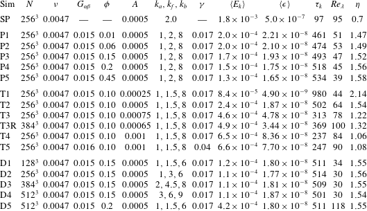
To study the droplet characteristics in these simulations, we segment the droplets in space (also known as clustering) by thresholding the droplet density field at a cutoff value
 $\unicode[STIX]{x1D70C}^{c}/\unicode[STIX]{x1D70C}_{\unicode[STIX]{x1D6FD}}^{in}=0.57$
(which is effectively the density along the interface where
$\unicode[STIX]{x1D70C}^{c}/\unicode[STIX]{x1D70C}_{\unicode[STIX]{x1D6FD}}^{in}=0.57$
(which is effectively the density along the interface where
 $\unicode[STIX]{x1D70C}^{c}\approx \unicode[STIX]{x1D70C}_{\unicode[STIX]{x1D6FC}}=\unicode[STIX]{x1D70C}_{\unicode[STIX]{x1D6FD}}$
) based on the algorithm used in Siebesma & Jonker (Reference Siebesma and Jonker2000). This allows us to identify and mark all lattice points within individual droplets, which gives the droplet volume
$\unicode[STIX]{x1D70C}^{c}\approx \unicode[STIX]{x1D70C}_{\unicode[STIX]{x1D6FC}}=\unicode[STIX]{x1D70C}_{\unicode[STIX]{x1D6FD}}$
) based on the algorithm used in Siebesma & Jonker (Reference Siebesma and Jonker2000). This allows us to identify and mark all lattice points within individual droplets, which gives the droplet volume
 $V$
, which in turn is used to calculate an effective diameter
$V$
, which in turn is used to calculate an effective diameter
 $d=(6V/\unicode[STIX]{x03C0})^{1/3}$
. Estimating the surface area of these droplets, which are in voxel form, requires more care. Often, the ‘GNU triangulation surface’ (GTS) library (Popinet & Jones Reference Popinet and Jones2004) is used in studies due to its efficient surface splitting operations (without the need for volumetric droplet segmentation). However, it was not used in this study as it did not provide a straightforward way of identifying droplets cut off at domain edges due to periodicity (an issue implicitly resolved by our segmentation algorithm). Also, the GTS library was found to under-predict the surface area of a sphere by around
$d=(6V/\unicode[STIX]{x03C0})^{1/3}$
. Estimating the surface area of these droplets, which are in voxel form, requires more care. Often, the ‘GNU triangulation surface’ (GTS) library (Popinet & Jones Reference Popinet and Jones2004) is used in studies due to its efficient surface splitting operations (without the need for volumetric droplet segmentation). However, it was not used in this study as it did not provide a straightforward way of identifying droplets cut off at domain edges due to periodicity (an issue implicitly resolved by our segmentation algorithm). Also, the GTS library was found to under-predict the surface area of a sphere by around
 $10\,\%$
. Instead, we use the method proposed by Windreich, Kiryati & Lohmann (Reference Windreich, Kiryati and Lohmann2003) (originally developed for medical MRI data) to calculate surface area directly from voxels using a look-up table which divides surface voxels into nine classes, and each class has a weighted contribution to the surface area. Using only the first four of these nine classes, the area estimation error for a sphere was found to decrease to
$10\,\%$
. Instead, we use the method proposed by Windreich, Kiryati & Lohmann (Reference Windreich, Kiryati and Lohmann2003) (originally developed for medical MRI data) to calculate surface area directly from voxels using a look-up table which divides surface voxels into nine classes, and each class has a weighted contribution to the surface area. Using only the first four of these nine classes, the area estimation error for a sphere was found to decrease to
 $1\,\%$
, which was sufficiently accurate for our study.
$1\,\%$
, which was sufficiently accurate for our study.
4.2 Effect of volume fraction
We now show results from simulations with varying dispersed-phase volume fractions
 $\unicode[STIX]{x1D719}\in \{0.01,0.06,0.15,0.2,0.45\}$
under identical turbulence forcing conditions (corresponding to P1–P5 in table 1). These simulations are performed for
$\unicode[STIX]{x1D719}\in \{0.01,0.06,0.15,0.2,0.45\}$
under identical turbulence forcing conditions (corresponding to P1–P5 in table 1). These simulations are performed for
 $10^{5}$
time steps. Figure 4 shows the dispersion formation process at various time instances starting from the initial spherical droplet of component
$10^{5}$
time steps. Figure 4 shows the dispersion formation process at various time instances starting from the initial spherical droplet of component
 $\unicode[STIX]{x1D6FD}$
shown as the iso-surfaces representing
$\unicode[STIX]{x1D6FD}$
shown as the iso-surfaces representing
 $\unicode[STIX]{x1D70C}_{\unicode[STIX]{x1D6FD}}=\unicode[STIX]{x1D70C}_{\unicode[STIX]{x1D6FC}}$
. The droplet begins to deform under the turbulent stresses, eventually breaking up to form a dispersion with a characteristic distribution.
$\unicode[STIX]{x1D70C}_{\unicode[STIX]{x1D6FD}}=\unicode[STIX]{x1D70C}_{\unicode[STIX]{x1D6FC}}$
. The droplet begins to deform under the turbulent stresses, eventually breaking up to form a dispersion with a characteristic distribution.
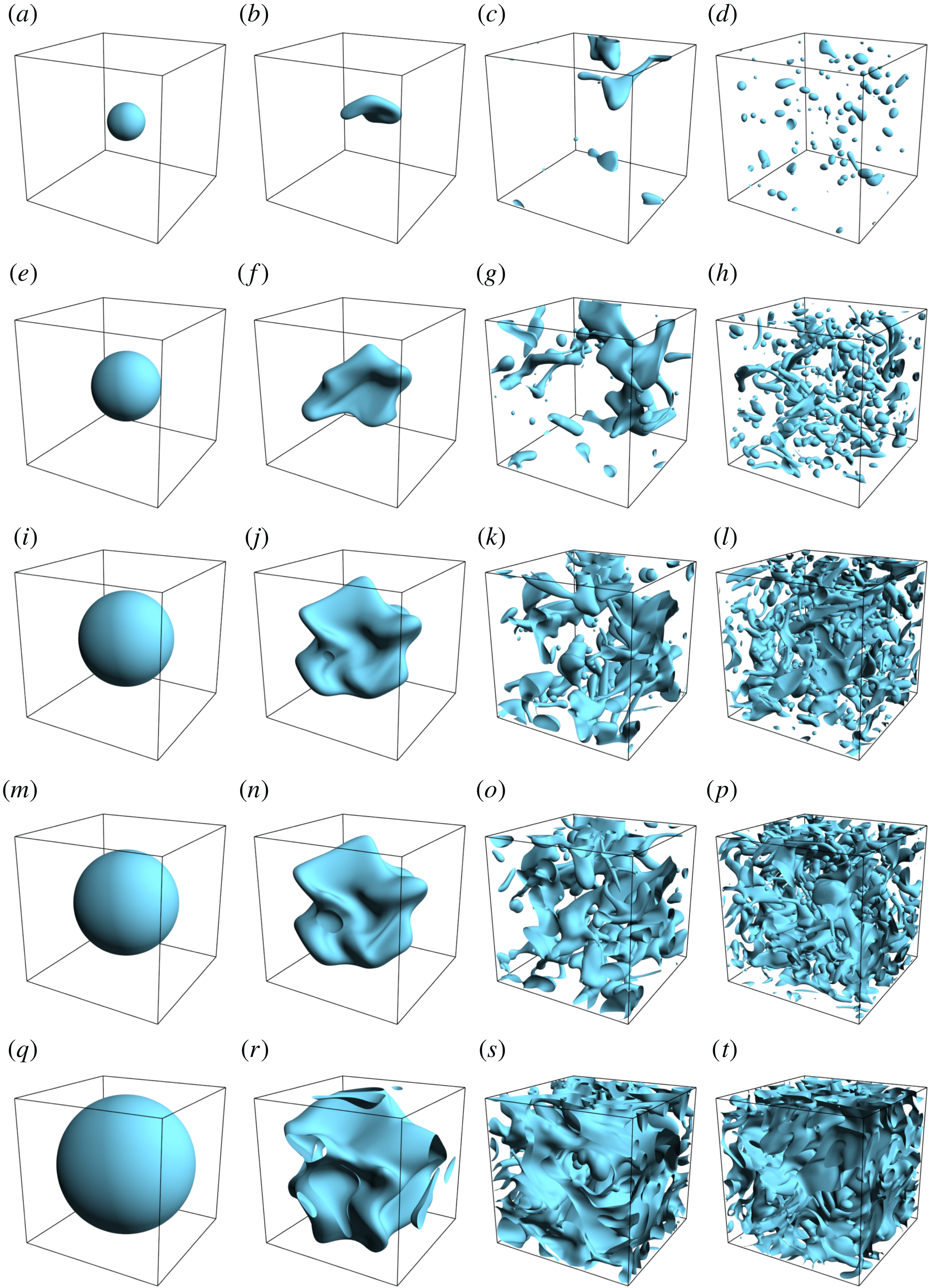
Figure 4. Dispersion formation under turbulence, for increasing volume fractions
 $\unicode[STIX]{x1D719}\in \{0.01,0.06,0.15,0.2,0.45\}$
corresponding to simulation P1–P5 in table 1 (top to bottom). The time instances are
$\unicode[STIX]{x1D719}\in \{0.01,0.06,0.15,0.2,0.45\}$
corresponding to simulation P1–P5 in table 1 (top to bottom). The time instances are
 $t/\unicode[STIX]{x1D70F}_{k}\approx 0,10,40,100$
(left to right), and the dispersions are subjected to identical turbulence forcing.
$t/\unicode[STIX]{x1D70F}_{k}\approx 0,10,40,100$
(left to right), and the dispersions are subjected to identical turbulence forcing.
Of the various volume fractions considered,
 $\unicode[STIX]{x1D719}=0.06$
and
$\unicode[STIX]{x1D719}=0.06$
and
 $0.15$
are most emulsion-like, i.e. they have a profusion of small droplets with a few large connected filaments. At
$0.15$
are most emulsion-like, i.e. they have a profusion of small droplets with a few large connected filaments. At
 $\unicode[STIX]{x1D719}=0.01$
, the dispersed phase is too dilute to be considered an emulsion, although the droplet dynamics is interesting as the number of droplets
$\unicode[STIX]{x1D719}=0.01$
, the dispersed phase is too dilute to be considered an emulsion, although the droplet dynamics is interesting as the number of droplets
 $N_{d}$
and their characteristic diameters
$N_{d}$
and their characteristic diameters
 $d$
are small, and hence most of the droplets remain dispersed with relatively few coalescence events, and when droplets do coalesce, they break up soon after. At
$d$
are small, and hence most of the droplets remain dispersed with relatively few coalescence events, and when droplets do coalesce, they break up soon after. At
 $\unicode[STIX]{x1D719}\geqslant 0.2$
, most of the fluid volume remains connected, which is aggravated by the enhanced coalescence inherent to diffuse interface methods (Komrakova et al.
Reference Komrakova, Eskin and Derksen2015a
; Roccon et al.
Reference Roccon, De Paoli, Zonta and Soldati2017). This in turn is due to insufficient resolution of the interface with respect to the droplet sizes (Shardt et al.
Reference Shardt, Derksen and Mitra2013), an effect we discuss more in depth in § 4.12. At higher turbulence intensity, the large connected regions can be expected to break into smaller droplets, and any coalescence will generate droplets of sizes larger than the maximum stable diameter, which will again break up.
$\unicode[STIX]{x1D719}\geqslant 0.2$
, most of the fluid volume remains connected, which is aggravated by the enhanced coalescence inherent to diffuse interface methods (Komrakova et al.
Reference Komrakova, Eskin and Derksen2015a
; Roccon et al.
Reference Roccon, De Paoli, Zonta and Soldati2017). This in turn is due to insufficient resolution of the interface with respect to the droplet sizes (Shardt et al.
Reference Shardt, Derksen and Mitra2013), an effect we discuss more in depth in § 4.12. At higher turbulence intensity, the large connected regions can be expected to break into smaller droplets, and any coalescence will generate droplets of sizes larger than the maximum stable diameter, which will again break up.
Before discussing further results, we first show a quantitative sample of the typical data from these simulations. In figure 5, the dispersed-phase density
 $\unicode[STIX]{x1D70C}_{\unicode[STIX]{x1D6FD}}$
, a single velocity component
$\unicode[STIX]{x1D70C}_{\unicode[STIX]{x1D6FD}}$
, a single velocity component
 $u_{x}$
and a single vorticity component
$u_{x}$
and a single vorticity component
 $\unicode[STIX]{x1D714}_{x}$
are shown along an arbitrary line passing through a droplet in the P4 dataset, along the
$\unicode[STIX]{x1D714}_{x}$
are shown along an arbitrary line passing through a droplet in the P4 dataset, along the
 $x$
-axis, at time
$x$
-axis, at time
 $t=190\unicode[STIX]{x1D70F}_{k}$
. At this time, the flow is well within the fully developed turbulent regime, along with the typical dispersion morphology having been attained. The first thing to note is that the velocity and vorticity fields are sufficiently well resolved and vary uniformly, i.e. there are no severe jumps due to spurious currents near the interfaces (only a small subtle spike), which shows that the physical velocity scales dominate over the spurious velocities.
$t=190\unicode[STIX]{x1D70F}_{k}$
. At this time, the flow is well within the fully developed turbulent regime, along with the typical dispersion morphology having been attained. The first thing to note is that the velocity and vorticity fields are sufficiently well resolved and vary uniformly, i.e. there are no severe jumps due to spurious currents near the interfaces (only a small subtle spike), which shows that the physical velocity scales dominate over the spurious velocities.
The velocity field in figure 5 varies gradually through the interface. This is reasonable due to the continuity of tangential stress across the interface and, we again emphasize, is inevitable due to the condition
 $\unicode[STIX]{x1D701}>\unicode[STIX]{x1D702}$
. Physically, this situation will not occur since the interface width is typically of the size
$\unicode[STIX]{x1D701}>\unicode[STIX]{x1D702}$
. Physically, this situation will not occur since the interface width is typically of the size
 $O(10^{-9})~[\text{m}]$
, and the smallest turbulent fluctuations, for micrometre sized droplets, may extend up to roughly
$O(10^{-9})~[\text{m}]$
, and the smallest turbulent fluctuations, for micrometre sized droplets, may extend up to roughly
 $O(10^{-6}{-}10^{-7})~[\text{m}]$
(while they depend on
$O(10^{-6}{-}10^{-7})~[\text{m}]$
(while they depend on
 $Re_{\unicode[STIX]{x1D706}}$
). The finite interface width is a limitation which will be encountered in any diffuse interface method, and which may be alleviated by adaptive mesh refinement near the interface as presented by Yu & Fan (Reference Yu and Fan2009), or by increasing the droplet resolution while keeping the interface thickness fixed (i.e. decreasing the Cahn number
$Re_{\unicode[STIX]{x1D706}}$
). The finite interface width is a limitation which will be encountered in any diffuse interface method, and which may be alleviated by adaptive mesh refinement near the interface as presented by Yu & Fan (Reference Yu and Fan2009), or by increasing the droplet resolution while keeping the interface thickness fixed (i.e. decreasing the Cahn number
 $Ch$
). The latter is done by adopting a larger simulation domain, as shown by Komrakova et al. (Reference Komrakova, Eskin and Derksen2015a
), and it also remedies other diffuse interface artifacts, as will be subsequently discussed.
$Ch$
). The latter is done by adopting a larger simulation domain, as shown by Komrakova et al. (Reference Komrakova, Eskin and Derksen2015a
), and it also remedies other diffuse interface artifacts, as will be subsequently discussed.
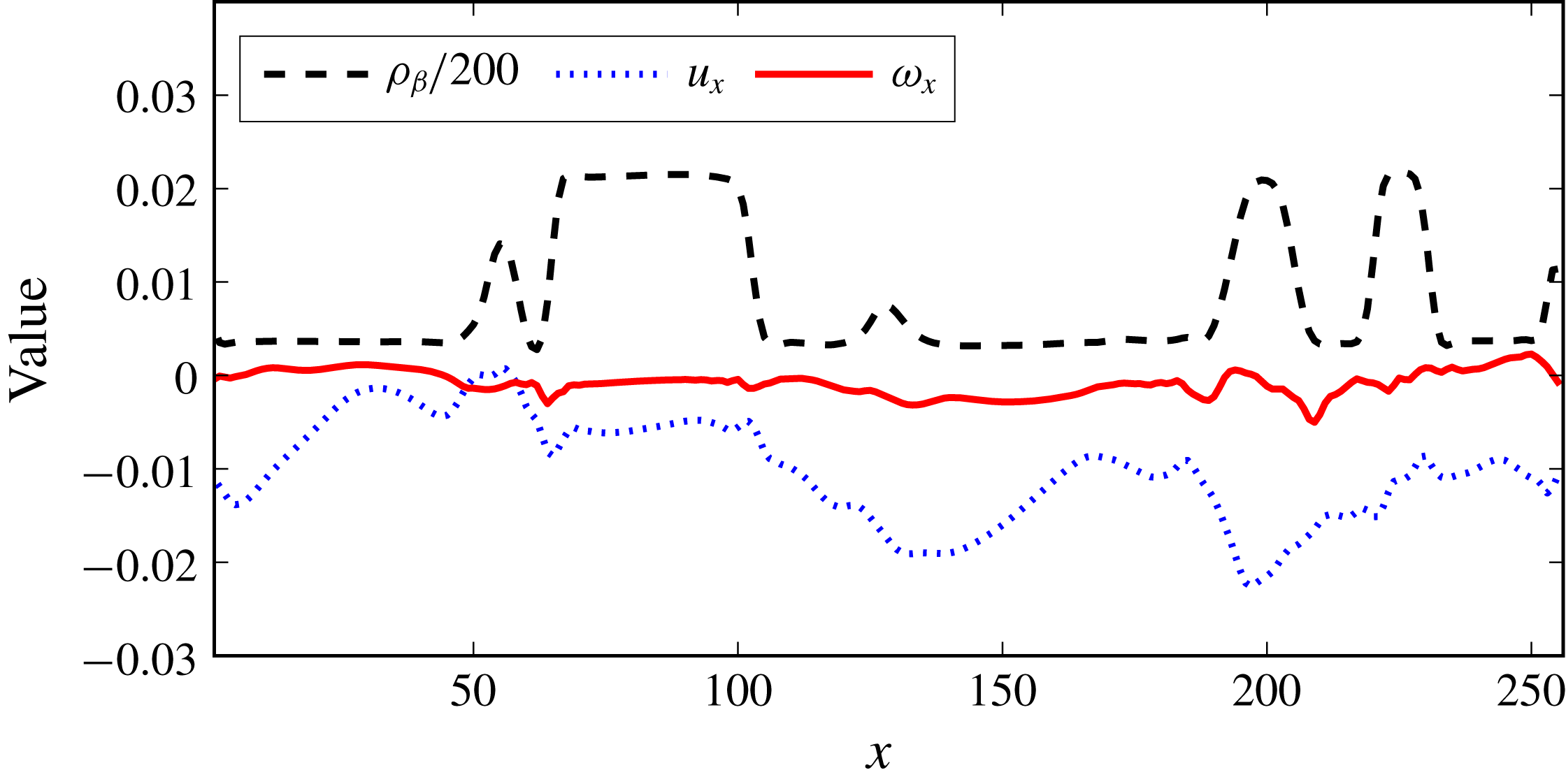
Figure 5. A sample of the dispersed-phase density (
 $\unicode[STIX]{x1D70C}_{\unicode[STIX]{x1D6FD}}$
, scaled by a factor of
$\unicode[STIX]{x1D70C}_{\unicode[STIX]{x1D6FD}}$
, scaled by a factor of
 $1/200$
),
$1/200$
),
 $x$
-velocity (
$x$
-velocity (
 $u_{x}$
) and
$u_{x}$
) and
 $x$
-vorticity (
$x$
-vorticity (
 $\unicode[STIX]{x1D714}_{x}$
) are shown along an arbitrary line passing through the P4 dataset along the
$\unicode[STIX]{x1D714}_{x}$
) are shown along an arbitrary line passing through the P4 dataset along the
 $x$
-axis, at time
$x$
-axis, at time
 $t=190\unicode[STIX]{x1D70F}_{k}$
when the turbulence and dispersion are fully developed.
$t=190\unicode[STIX]{x1D70F}_{k}$
when the turbulence and dispersion are fully developed.
4.3 Phase fraction evolution
Figure 6 shows the evolution of the dispersed-phase volume fraction
 $\unicode[STIX]{x1D719}$
normalized by the initial volume fraction
$\unicode[STIX]{x1D719}$
normalized by the initial volume fraction
 $\unicode[STIX]{x1D719}_{0}$
. There is a clear decrease over time (up to around
$\unicode[STIX]{x1D719}_{0}$
. There is a clear decrease over time (up to around
 $100\unicode[STIX]{x1D70F}_{k}$
) in the relative volume fraction, beyond which the value plateaus to a level around which it continues to oscillate (this will be confirmed subsequently from simulations T1–T5 in § 4.8 which were performed for a five times longer duration). This relative reduction in
$100\unicode[STIX]{x1D70F}_{k}$
) in the relative volume fraction, beyond which the value plateaus to a level around which it continues to oscillate (this will be confirmed subsequently from simulations T1–T5 in § 4.8 which were performed for a five times longer duration). This relative reduction in
 $\unicode[STIX]{x1D719}$
is more pronounced at lower
$\unicode[STIX]{x1D719}$
is more pronounced at lower
 $\unicode[STIX]{x1D719}$
values (up to around
$\unicode[STIX]{x1D719}$
values (up to around
 $30\,\%$
) than at higher
$30\,\%$
) than at higher
 $\unicode[STIX]{x1D719}$
(around 2 %–5 %). Note that this is not a mass conservation issue, as the total component mass is perfectly conserved in the system, and only the amount of component
$\unicode[STIX]{x1D719}$
(around 2 %–5 %). Note that this is not a mass conservation issue, as the total component mass is perfectly conserved in the system, and only the amount of component
 $\unicode[STIX]{x1D6FD}$
present as the dispersed phase reduces, which gets dissolved in the
$\unicode[STIX]{x1D6FD}$
present as the dispersed phase reduces, which gets dissolved in the
 $\unicode[STIX]{x1D6FC}$
-rich (continuous phase) region. This is also why the relative decrease in
$\unicode[STIX]{x1D6FC}$
-rich (continuous phase) region. This is also why the relative decrease in
 $\unicode[STIX]{x1D719}$
is strongest for
$\unicode[STIX]{x1D719}$
is strongest for
 $\unicode[STIX]{x1D719}=0.01$
, as the dissolution of
$\unicode[STIX]{x1D719}=0.01$
, as the dissolution of
 $\unicode[STIX]{x1D6FD}$
into the continuous phase is provided by a very low number of droplets.
$\unicode[STIX]{x1D6FD}$
into the continuous phase is provided by a very low number of droplets.
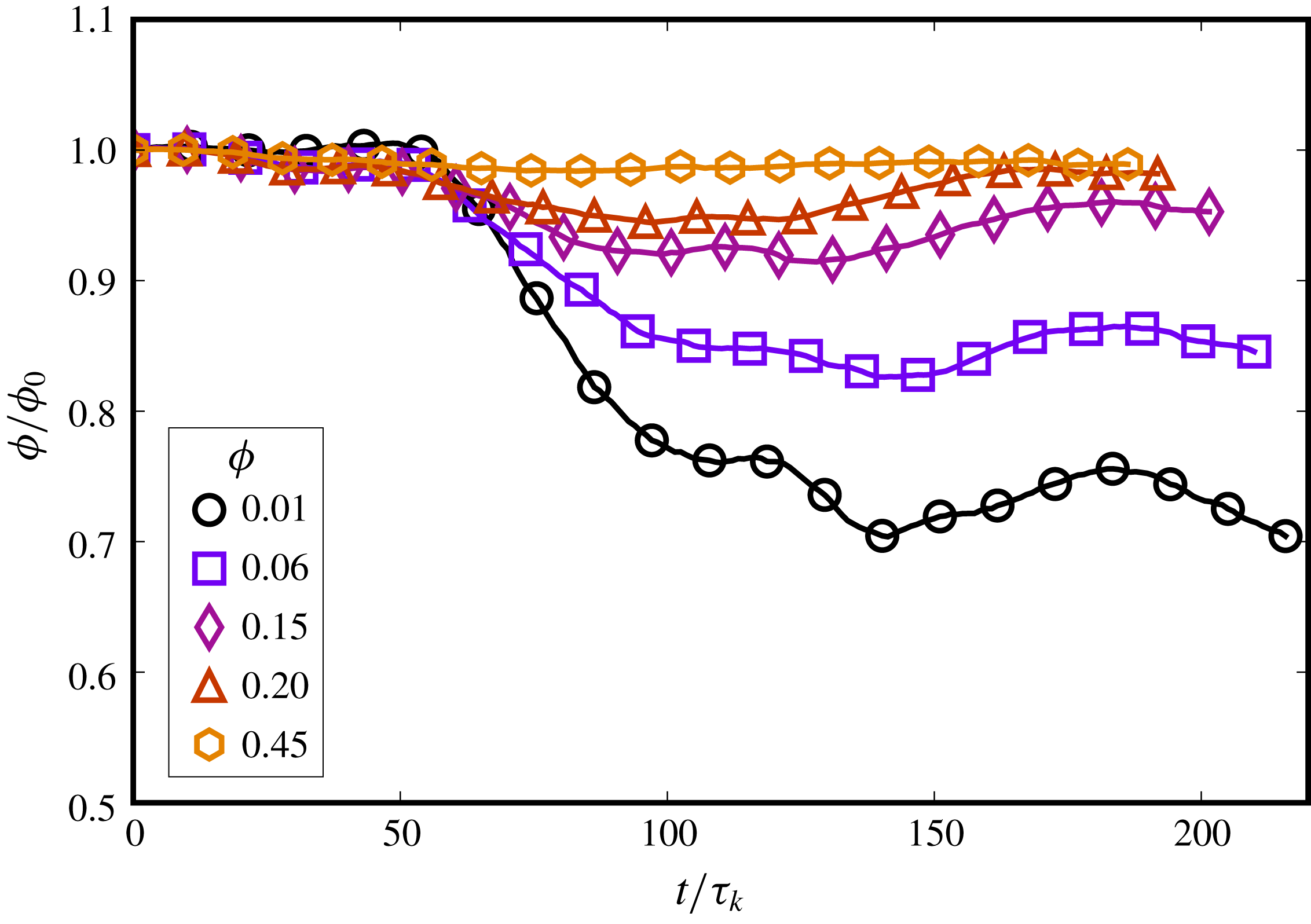
Figure 6. Evolution of volume fraction
 $\unicode[STIX]{x1D719}$
normalized by the initial volume fraction
$\unicode[STIX]{x1D719}$
normalized by the initial volume fraction
 $\unicode[STIX]{x1D719}_{0}$
, for the same turbulence intensity across simulations. There is more droplet dissolution for lower
$\unicode[STIX]{x1D719}_{0}$
, for the same turbulence intensity across simulations. There is more droplet dissolution for lower
 $\unicode[STIX]{x1D719}$
values, while the decrease is not monotonic as new smaller droplets can be formed as well.
$\unicode[STIX]{x1D719}$
values, while the decrease is not monotonic as new smaller droplets can be formed as well.
The reason for the reduction in
 $\unicode[STIX]{x1D719}$
is twofold. First is the dissolution of small droplets due to a finite interface width, which is an issue inherent to most diffuse interface methods. Yue, Zhou & Feng (Reference Yue, Zhou and Feng2007) showed that there is a slow drift in the droplet density due to diffusion, which also leads to droplet shrinkage. They also show that a small droplet in a large domain is more prone to dissolution, which is reflected in figure 6 where the lowest
$\unicode[STIX]{x1D719}$
is twofold. First is the dissolution of small droplets due to a finite interface width, which is an issue inherent to most diffuse interface methods. Yue, Zhou & Feng (Reference Yue, Zhou and Feng2007) showed that there is a slow drift in the droplet density due to diffusion, which also leads to droplet shrinkage. They also show that a small droplet in a large domain is more prone to dissolution, which is reflected in figure 6 where the lowest
 $\unicode[STIX]{x1D719}$
simulation suffers most from droplet dissolution. This effect is also tied to the Cahn number
$\unicode[STIX]{x1D719}$
simulation suffers most from droplet dissolution. This effect is also tied to the Cahn number
 $Ch$
. If
$Ch$
. If
 $Ch\sim O(1)$
(or greater), the droplet becomes unstable and is prone to dissolution. On the other hand, Shardt et al. (Reference Shardt, Derksen and Mitra2013) showed for droplet collision in shear flow that coalescence is inhibited with decreasing
$Ch\sim O(1)$
(or greater), the droplet becomes unstable and is prone to dissolution. On the other hand, Shardt et al. (Reference Shardt, Derksen and Mitra2013) showed for droplet collision in shear flow that coalescence is inhibited with decreasing
 $Ch$
. In the limit of
$Ch$
. In the limit of
 $Ch\rightarrow 0$
, coalescence would cease to occur, while increasing
$Ch\rightarrow 0$
, coalescence would cease to occur, while increasing
 $Ch$
leads to coalescence at higher capillary numbers. These considerations mandate having a finite
$Ch$
leads to coalescence at higher capillary numbers. These considerations mandate having a finite
 $Ch$
in the range
$Ch$
in the range
 $0<Ch\ll 1$
(for all droplet sizes in the system) for achieving steady-state simulations while allowing for both coalescence and breakup. The effect of Cahn number on droplet dissolution is analysed subsequently in § 4.8.
$0<Ch\ll 1$
(for all droplet sizes in the system) for achieving steady-state simulations while allowing for both coalescence and breakup. The effect of Cahn number on droplet dissolution is analysed subsequently in § 4.8.
The second reason for the reduction in
 $\unicode[STIX]{x1D719}$
is its sensitivity to the segmentation threshold. In appendix A we demonstrate that only this result, i.e. the evolution of the volume fraction, depends on the choice of the segmentation threshold. Part of the droplet-phase fraction goes into constituting the increased interfacial region (i.e. roughly the total surface area of all droplets
$\unicode[STIX]{x1D719}$
is its sensitivity to the segmentation threshold. In appendix A we demonstrate that only this result, i.e. the evolution of the volume fraction, depends on the choice of the segmentation threshold. Part of the droplet-phase fraction goes into constituting the increased interfacial region (i.e. roughly the total surface area of all droplets
 $S_{A}$
multiplied by the interface width
$S_{A}$
multiplied by the interface width
 $\unicode[STIX]{x1D701}$
). On slightly varying the segmentation threshold to lower values (so that it is closer to
$\unicode[STIX]{x1D701}$
). On slightly varying the segmentation threshold to lower values (so that it is closer to
 $\unicode[STIX]{x1D70C}_{\unicode[STIX]{x1D6FD}}^{out}$
), the apparent volume fraction loss is reduced (which may indicate that
$\unicode[STIX]{x1D70C}_{\unicode[STIX]{x1D6FD}}^{out}$
), the apparent volume fraction loss is reduced (which may indicate that
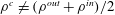 $\unicode[STIX]{x1D70C}^{c}\neq (\unicode[STIX]{x1D70C}^{out}+\unicode[STIX]{x1D70C}^{in})/2$
), although the exact choice of
$\unicode[STIX]{x1D70C}^{c}\neq (\unicode[STIX]{x1D70C}^{out}+\unicode[STIX]{x1D70C}^{in})/2$
), although the exact choice of
 $\unicode[STIX]{x1D70C}^{c}$
does not change our results. Further, the reduction in
$\unicode[STIX]{x1D70C}^{c}$
does not change our results. Further, the reduction in
 $\unicode[STIX]{x1D719}$
is also not monotonic, as mass of component
$\unicode[STIX]{x1D719}$
is also not monotonic, as mass of component
 $\unicode[STIX]{x1D6FD}$
dissolved in the
$\unicode[STIX]{x1D6FD}$
dissolved in the
 $\unicode[STIX]{x1D6FC}$
-rich region can eventually accumulate inside other droplets.
$\unicode[STIX]{x1D6FC}$
-rich region can eventually accumulate inside other droplets.
Droplet dissolution can be a debilitating numerical issue, where for instance Biferale et al. (Reference Biferale, Perlekar, Sbragaglia, Srivastava and Toschi2011) and Perlekar et al. (Reference Perlekar, Biferale, Sbragaglia, Srivastava and Toschi2012) had to resort to artificially inflating droplets to maintain a constant phase fraction and Komrakova et al. (Reference Komrakova, Eskin and Derksen2015a
) reported that they could not attain steady-state simulations with the free-energy LB method at low volume fractions as all droplets dissolved away into the continuous phase. In our PP-LB simulations, this issue is due to an interplay of three main factors: (i) the liquid–liquid repulsion
 $G_{\unicode[STIX]{x1D6FC}\unicode[STIX]{x1D6FD}}$
which keeps the two components demixed; (ii) the turbulence intensity which breaks large droplets into smaller ones; and (iii) the phase fraction which at low values makes
$G_{\unicode[STIX]{x1D6FC}\unicode[STIX]{x1D6FD}}$
which keeps the two components demixed; (ii) the turbulence intensity which breaks large droplets into smaller ones; and (iii) the phase fraction which at low values makes
 $\unicode[STIX]{x1D70C}_{\unicode[STIX]{x1D6FD}}^{out}\approx \unicode[STIX]{x1D70C}_{\unicode[STIX]{x1D6FD}}^{avg}$
(i.e. at low
$\unicode[STIX]{x1D70C}_{\unicode[STIX]{x1D6FD}}^{out}\approx \unicode[STIX]{x1D70C}_{\unicode[STIX]{x1D6FD}}^{avg}$
(i.e. at low
 $\unicode[STIX]{x1D719}$
, phase segregation can become weaker). Despite being present, droplet dissolution is limited to a minor effect in our simulations. More precisely, the PP-LB method employed in this study can be used to simulate, reasonably well, certain regions of the turbulent emulsions parameter space where droplet dissolution is not significant. Namely, for a given turbulence intensity (
$\unicode[STIX]{x1D719}$
, phase segregation can become weaker). Despite being present, droplet dissolution is limited to a minor effect in our simulations. More precisely, the PP-LB method employed in this study can be used to simulate, reasonably well, certain regions of the turbulent emulsions parameter space where droplet dissolution is not significant. Namely, for a given turbulence intensity (
 $Re_{\unicode[STIX]{x1D706}}$
), there will be a critical lower bound on the interfacial tension
$Re_{\unicode[STIX]{x1D706}}$
), there will be a critical lower bound on the interfacial tension
 $\unicode[STIX]{x1D6FE}_{c}$
such that droplets with
$\unicode[STIX]{x1D6FE}_{c}$
such that droplets with
 $\unicode[STIX]{x1D6FE}>\unicode[STIX]{x1D6FE}_{c}$
can be simulated. For increasing
$\unicode[STIX]{x1D6FE}>\unicode[STIX]{x1D6FE}_{c}$
can be simulated. For increasing
 $Re_{\unicode[STIX]{x1D706}}$
,
$Re_{\unicode[STIX]{x1D706}}$
,
 $\unicode[STIX]{x1D6FE}_{c}$
would increase as well, and its exact dependence on
$\unicode[STIX]{x1D6FE}_{c}$
would increase as well, and its exact dependence on
 $Re_{\unicode[STIX]{x1D706}}$
could be investigated by numerically mapping the phase space, which is outside the scope of the current study. Similarly, there will be a lower bound on the value of
$Re_{\unicode[STIX]{x1D706}}$
could be investigated by numerically mapping the phase space, which is outside the scope of the current study. Similarly, there will be a lower bound on the value of
 $\unicode[STIX]{x1D719}$
, below which all droplets will dissolve due to weak phase segregation when
$\unicode[STIX]{x1D719}$
, below which all droplets will dissolve due to weak phase segregation when
 $\unicode[STIX]{x1D70C}_{\unicode[STIX]{x1D6FD}}^{out}\approx \unicode[STIX]{x1D70C}_{\unicode[STIX]{x1D6FD}}^{avg}$
. Considering these related effects, we restrict ourselves to a parameter range where we can attain long stable simulations to collect meaningful statistics pertaining to the droplet coalescence and breakup equilibrium.
$\unicode[STIX]{x1D70C}_{\unicode[STIX]{x1D6FD}}^{out}\approx \unicode[STIX]{x1D70C}_{\unicode[STIX]{x1D6FD}}^{avg}$
. Considering these related effects, we restrict ourselves to a parameter range where we can attain long stable simulations to collect meaningful statistics pertaining to the droplet coalescence and breakup equilibrium.
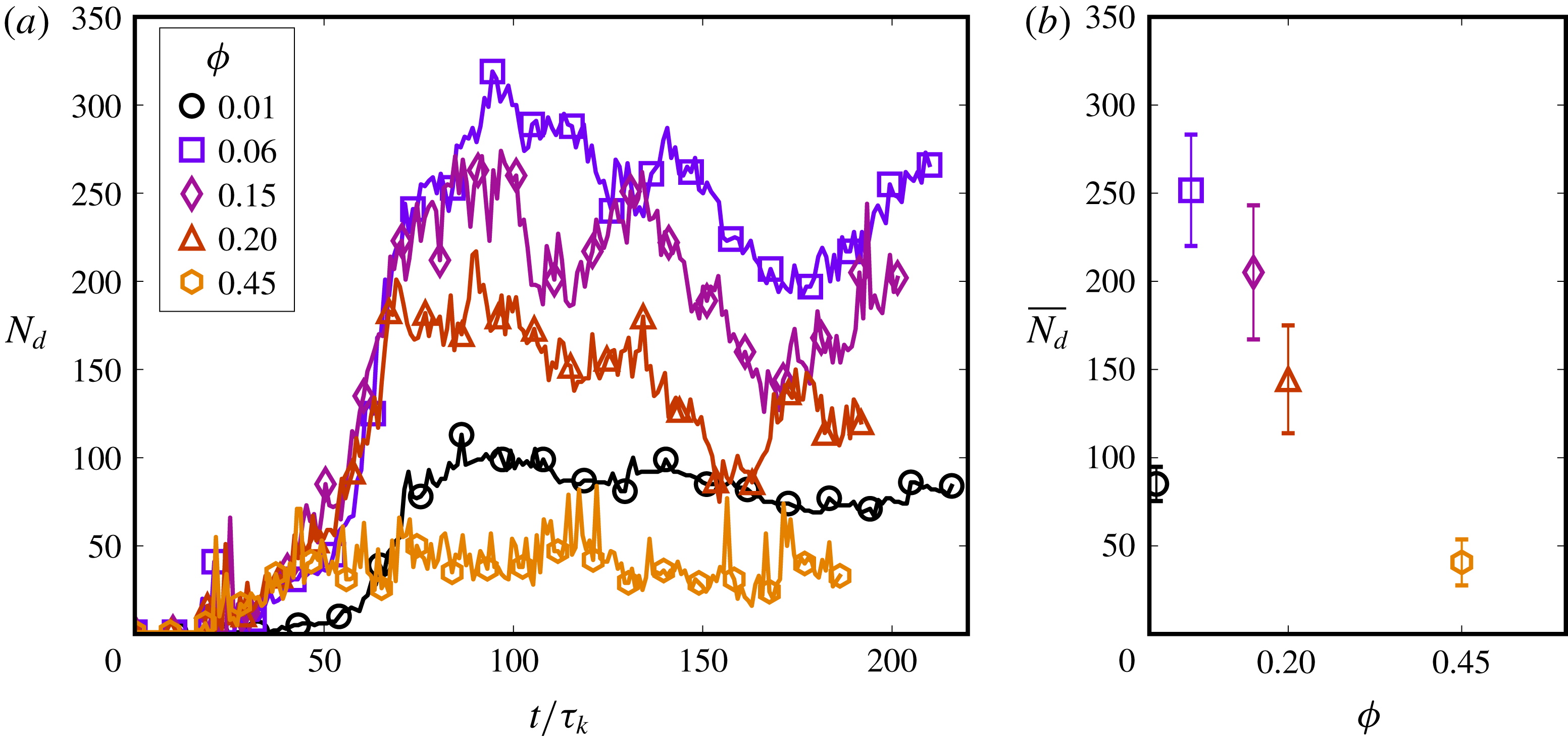
Figure 7. Evolution of the number of droplets (
 $N_{d}$
) in the system, which attains its characteristic value around
$N_{d}$
) in the system, which attains its characteristic value around
 $75\unicode[STIX]{x1D70F}_{k}$
and oscillates around a temporal mean. The
$75\unicode[STIX]{x1D70F}_{k}$
and oscillates around a temporal mean. The
 $\unicode[STIX]{x1D719}=0.06$
case produces the highest number of droplets (around 250), which is seen in (b) where
$\unicode[STIX]{x1D719}=0.06$
case produces the highest number of droplets (around 250), which is seen in (b) where
 $\overline{N_{d}}$
is
$\overline{N_{d}}$
is
 $N_{d}$
averaged from
$N_{d}$
averaged from
 $75\unicode[STIX]{x1D70F}_{k}$
to
$75\unicode[STIX]{x1D70F}_{k}$
to
 $200\unicode[STIX]{x1D70F}_{k}$
, and the error bars show the standard deviation.
$200\unicode[STIX]{x1D70F}_{k}$
, and the error bars show the standard deviation.
Figure 8. Evolution of the droplet number density
 $N_{d}$
and the relative volume fraction
$N_{d}$
and the relative volume fraction
 $\unicode[STIX]{x1D719}/\unicode[STIX]{x1D719}_{0}$
is compared for different dispersed-phase initial conditions for simulation P3 with
$\unicode[STIX]{x1D719}/\unicode[STIX]{x1D719}_{0}$
is compared for different dispersed-phase initial conditions for simulation P3 with
 $\unicode[STIX]{x1D719}=0.15$
. The ‘single’ case starts with one droplet of
$\unicode[STIX]{x1D719}=0.15$
. The ‘single’ case starts with one droplet of
 $\unicode[STIX]{x1D719}=0.15$
while the ‘multiple’ case distributes the same droplet volume over
$\unicode[STIX]{x1D719}=0.15$
while the ‘multiple’ case distributes the same droplet volume over
 $216$
smaller droplets, all equally spaced. Both cases proceed to the same final state, with almost the same average morphology, and the coincidence is expected to increase over a longer simulation duration.
$216$
smaller droplets, all equally spaced. Both cases proceed to the same final state, with almost the same average morphology, and the coincidence is expected to increase over a longer simulation duration.

Figure 9. Droplet size distributions for varying volume fractions (on a
 $256^{3}$
domain). Case (a)
$256^{3}$
domain). Case (a)
 $\unicode[STIX]{x1D719}=0.01$
shows a peak around
$\unicode[STIX]{x1D719}=0.01$
shows a peak around
 $d/\unicode[STIX]{x1D702}\approx 10$
, which rapidly falls off at higher
$d/\unicode[STIX]{x1D702}\approx 10$
, which rapidly falls off at higher
 $d/\unicode[STIX]{x1D702}$
. Cases (b)
$d/\unicode[STIX]{x1D702}$
. Cases (b)
 $\unicode[STIX]{x1D719}=0.06$
and (c)
$\unicode[STIX]{x1D719}=0.06$
and (c)
 $\unicode[STIX]{x1D719}=0.15$
have a wider range of droplet sizes, and the distribution follows a
$\unicode[STIX]{x1D719}=0.15$
have a wider range of droplet sizes, and the distribution follows a
 $d^{-10/3}$
scaling in the range
$d^{-10/3}$
scaling in the range
 $d>d_{max}$
. The distributions also weakly show a
$d>d_{max}$
. The distributions also weakly show a
 $d^{-3/2}$
scaling over some droplet sizes in the range
$d^{-3/2}$
scaling over some droplet sizes in the range
 $d<d_{max}$
(most prominently case (d)). For
$d<d_{max}$
(most prominently case (d)). For
 $\unicode[STIX]{x1D719}\geqslant 0.20$
, a significant secondary peak at high
$\unicode[STIX]{x1D719}\geqslant 0.20$
, a significant secondary peak at high
 $d/\unicode[STIX]{x1D702}$
indicates the few large connected regions that form in the periodic simulation domain, along with multiple smaller satellite droplets. The vertical dashed line shows the Hinze scale and the vertical dotted line marks the limit to the left of which the Cahn number
$d/\unicode[STIX]{x1D702}$
indicates the few large connected regions that form in the periodic simulation domain, along with multiple smaller satellite droplets. The vertical dashed line shows the Hinze scale and the vertical dotted line marks the limit to the left of which the Cahn number
 $Ch\sim O(1)$
and droplets become unstable.
$Ch\sim O(1)$
and droplets become unstable.
4.4 Droplet number density evolution
Figure 7 shows the evolution of the number of droplets (
 $N_{d}$
) in the system for varying
$N_{d}$
) in the system for varying
 $\unicode[STIX]{x1D719}$
. It is seen that
$\unicode[STIX]{x1D719}$
. It is seen that
 $N_{d}$
begins to increase following the first breakup events around
$N_{d}$
begins to increase following the first breakup events around
 $25\unicode[STIX]{x1D70F}_{k}$
and rises steadily to its characteristic value at approximately
$25\unicode[STIX]{x1D70F}_{k}$
and rises steadily to its characteristic value at approximately
 $75\unicode[STIX]{x1D70F}_{k}$
, around which it continues to oscillate. The oscillations in
$75\unicode[STIX]{x1D70F}_{k}$
, around which it continues to oscillate. The oscillations in
 $N_{d}$
are indicative of competing coalescence and breakup dynamics. The falls in the
$N_{d}$
are indicative of competing coalescence and breakup dynamics. The falls in the
 $N_{d}$
evolution profiles are due to coalescence events, which generate droplets of large sizes that are unstable. These droplets then break up under turbulent stresses and
$N_{d}$
evolution profiles are due to coalescence events, which generate droplets of large sizes that are unstable. These droplets then break up under turbulent stresses and
 $N_{d}$
increases again. Breakup is delayed for
$N_{d}$
increases again. Breakup is delayed for
 $\unicode[STIX]{x1D719}=0.01$
as compared to the other cases and
$\unicode[STIX]{x1D719}=0.01$
as compared to the other cases and
 $N_{d}$
only begins to increase around
$N_{d}$
only begins to increase around
 $50\unicode[STIX]{x1D70F}_{k}$
. This is because the size of the initial droplet is much smaller (
$50\unicode[STIX]{x1D70F}_{k}$
. This is because the size of the initial droplet is much smaller (
 ${\sim}64~[\text{lu}]$
) than the forcing wavelength (
${\sim}64~[\text{lu}]$
) than the forcing wavelength (
 ${\sim}128~[\text{lu}]$
), and the droplet starts to advect initially, as seen from figure 4. When smaller scales are generated (around
${\sim}128~[\text{lu}]$
), and the droplet starts to advect initially, as seen from figure 4. When smaller scales are generated (around
 $50\unicode[STIX]{x1D70F}_{k}$
, as can be seen from the enstrophy evolution in figure 1), the droplet begins to shear and break. The evolution of
$50\unicode[STIX]{x1D70F}_{k}$
, as can be seen from the enstrophy evolution in figure 1), the droplet begins to shear and break. The evolution of
 $N_{d}$
does not show large fluctuations for
$N_{d}$
does not show large fluctuations for
 $\unicode[STIX]{x1D719}=0.01$
due to relatively fewer coalescence and breakup events in this case, which is because the droplets are smaller and more distant from each other than in higher
$\unicode[STIX]{x1D719}=0.01$
due to relatively fewer coalescence and breakup events in this case, which is because the droplets are smaller and more distant from each other than in higher
 $\unicode[STIX]{x1D719}$
cases.
$\unicode[STIX]{x1D719}$
cases.
Although
 $\unicode[STIX]{x1D719}=0.15$
and
$\unicode[STIX]{x1D719}=0.15$
and
 $0.2$
simulations have a larger volume of fluid
$0.2$
simulations have a larger volume of fluid
 $\unicode[STIX]{x1D6FD}$
, the number of droplets generated is lower than for
$\unicode[STIX]{x1D6FD}$
, the number of droplets generated is lower than for
 $\unicode[STIX]{x1D719}=0.06$
. This is because of a higher propensity for coalescence in these systems, which generates large connected regions and smaller satellite droplets. This is most prominently seen for
$\unicode[STIX]{x1D719}=0.06$
. This is because of a higher propensity for coalescence in these systems, which generates large connected regions and smaller satellite droplets. This is most prominently seen for
 $\unicode[STIX]{x1D719}=0.45$
, where
$\unicode[STIX]{x1D719}=0.45$
, where
 $N_{d}$
is even lower than for
$N_{d}$
is even lower than for
 $\unicode[STIX]{x1D719}=0.01$
, as most of the fluid forms extended filaments that remain connected across the periodic boundaries. Increasing the turbulence intensity can be expected to generate more droplets at higher
$\unicode[STIX]{x1D719}=0.01$
, as most of the fluid forms extended filaments that remain connected across the periodic boundaries. Increasing the turbulence intensity can be expected to generate more droplets at higher
 $\unicode[STIX]{x1D719}$
, and hence for a given
$\unicode[STIX]{x1D719}$
, and hence for a given
 $Re_{\unicode[STIX]{x1D706}}$
, there will be a specific
$Re_{\unicode[STIX]{x1D706}}$
, there will be a specific
 $\unicode[STIX]{x1D719}$
that maximizes the number of droplets formed and hence produce a more emulsion-like droplet size distribution.
$\unicode[STIX]{x1D719}$
that maximizes the number of droplets formed and hence produce a more emulsion-like droplet size distribution.
Once the turbulent emulsion achieves its ‘steady state’ (albeit fluctuating), it holds no memory of the initial conditions of the dispersed phase. To demonstrate this, simulation P3 (with
 $\unicode[STIX]{x1D719}=0.15$
) is repeated, where instead of a single droplet,
$\unicode[STIX]{x1D719}=0.15$
) is repeated, where instead of a single droplet,
 $216$
smaller droplets (together also comprising
$216$
smaller droplets (together also comprising
 $\unicode[STIX]{x1D719}=0.15$
), equally spaced on a regular lattice, are initialized. Figure 8 shows the droplet number density and volume fraction evolution for the two initial conditions for P3. The multiple droplet system proceeds with dominant coalescence up to
$\unicode[STIX]{x1D719}=0.15$
), equally spaced on a regular lattice, are initialized. Figure 8 shows the droplet number density and volume fraction evolution for the two initial conditions for P3. The multiple droplet system proceeds with dominant coalescence up to
 $t\approx 30\unicode[STIX]{x1D70F}_{k}$
, after which breakup and coalescence begin to occur simultaneously. Then
$t\approx 30\unicode[STIX]{x1D70F}_{k}$
, after which breakup and coalescence begin to occur simultaneously. Then
 $N_{d}$
soon reaches its typical value, similar to the single droplet initialization, and the time-averaged droplet number density
$N_{d}$
soon reaches its typical value, similar to the single droplet initialization, and the time-averaged droplet number density
 $\overline{N_{d}}$
(between
$\overline{N_{d}}$
(between
 $75\unicode[STIX]{x1D70F}_{k}$
–
$75\unicode[STIX]{x1D70F}_{k}$
–
 $200\unicode[STIX]{x1D70F}_{k}$
, shown in the inset of panel (a)) is very similar for both cases. Although not equal within the duration of these simulations,
$200\unicode[STIX]{x1D70F}_{k}$
, shown in the inset of panel (a)) is very similar for both cases. Although not equal within the duration of these simulations,
 $\overline{N_{d}}$
can be expected to converge to the same value when averaged over a longer duration. The relative volume fraction evolution is also very similar for both initial conditions, in particular for
$\overline{N_{d}}$
can be expected to converge to the same value when averaged over a longer duration. The relative volume fraction evolution is also very similar for both initial conditions, in particular for
 $t>150\unicode[STIX]{x1D70F}_{k}$
.
$t>150\unicode[STIX]{x1D70F}_{k}$
.
4.5 Droplet size distribution
Figure 9 shows the distribution of the equivalent droplet diameter
 $d=(6V/\unicode[STIX]{x03C0})^{1/3}$
(where
$d=(6V/\unicode[STIX]{x03C0})^{1/3}$
(where
 $V$
is the droplet volume) for varying
$V$
is the droplet volume) for varying
 $\unicode[STIX]{x1D719}$
(calculated with 25 000–35 000 droplets identified between times
$\unicode[STIX]{x1D719}$
(calculated with 25 000–35 000 droplets identified between times
 $75\unicode[STIX]{x1D70F}_{k}$
–
$75\unicode[STIX]{x1D70F}_{k}$
–
 $200\unicode[STIX]{x1D70F}_{k}$
, sampled at each
$200\unicode[STIX]{x1D70F}_{k}$
, sampled at each
 $\unicode[STIX]{x1D70F}_{k}$
). Case (a)
$\unicode[STIX]{x1D70F}_{k}$
). Case (a)
 $\unicode[STIX]{x1D719}=0.01$
shows a peak around
$\unicode[STIX]{x1D719}=0.01$
shows a peak around
 $d/\unicode[STIX]{x1D702}\approx 10$
, beyond which the distribution rapidly falls off due to the dispersion being dilute (see figure 4
d). Due to infrequent coalescence, large droplets are not formed very often. This was also reflected in the
$d/\unicode[STIX]{x1D702}\approx 10$
, beyond which the distribution rapidly falls off due to the dispersion being dilute (see figure 4
d). Due to infrequent coalescence, large droplets are not formed very often. This was also reflected in the
 $N_{d}$
evolution (figure 7) which does not fluctuate as much as higher
$N_{d}$
evolution (figure 7) which does not fluctuate as much as higher
 $\unicode[STIX]{x1D719}$
simulations. Cases (c,d) with
$\unicode[STIX]{x1D719}$
simulations. Cases (c,d) with
 $\unicode[STIX]{x1D719}\geqslant 0.15$
(and to a small extent case b) show two power-law regimes in the droplet distribution. The occurrence of droplets of sizes
$\unicode[STIX]{x1D719}\geqslant 0.15$
(and to a small extent case b) show two power-law regimes in the droplet distribution. The occurrence of droplets of sizes
 $d>d_{max}$
(where
$d>d_{max}$
(where
 $d_{max}$
is the Hinze (Reference Hinze1955) scale) falls off with a
$d_{max}$
is the Hinze (Reference Hinze1955) scale) falls off with a
 $d^{-10/3}$
slope, while droplets of sizes
$d^{-10/3}$
slope, while droplets of sizes
 $d<d_{max}$
show a weak
$d<d_{max}$
show a weak
 $d^{-3/2}$
slope (the latter is more prominent in figure 9
d).
$d^{-3/2}$
slope (the latter is more prominent in figure 9
d).
The
 $d^{-10/3}$
scaling was originally postulated and shown for air bubbles in breaking ocean waves by Garrett et al. (Reference Garrett, Li and Farmer2000). The scaling was derived from dimensional and mechanistic arguments (that bubble lifetimes depended on bubble sizes), with assumptions of a purely inertial breakup process that depends only on the turbulence intensity (determined by
$d^{-10/3}$
scaling was originally postulated and shown for air bubbles in breaking ocean waves by Garrett et al. (Reference Garrett, Li and Farmer2000). The scaling was derived from dimensional and mechanistic arguments (that bubble lifetimes depended on bubble sizes), with assumptions of a purely inertial breakup process that depends only on the turbulence intensity (determined by
 $\unicode[STIX]{x1D716}$
) and the rate of supply of the dispersed phase (i.e. volume of air entrained per volume of water per second). This led to a
$\unicode[STIX]{x1D716}$
) and the rate of supply of the dispersed phase (i.e. volume of air entrained per volume of water per second). This led to a
 $d^{-10/3}$
scaling for the droplet spectrum
$d^{-10/3}$
scaling for the droplet spectrum
 $P(d)$
, which was again verified by Deane & Stokes (Reference Deane and Stokes2002) for air bubbles above the Hinze scale in breaking waves. Deane & Stokes (Reference Deane and Stokes2002) further showed that bubble sizes below the Hinze scale follow a
$P(d)$
, which was again verified by Deane & Stokes (Reference Deane and Stokes2002) for air bubbles above the Hinze scale in breaking waves. Deane & Stokes (Reference Deane and Stokes2002) further showed that bubble sizes below the Hinze scale follow a
 $d^{-3/2}$
distribution, which was also dimensionally motivated (while including surface tension effects for smaller droplets). They found the scalings to hold for a brief period before the turbulence decayed. Skartlien et al. (Reference Skartlien, Sollum and Schumann2013) showed that the droplet distribution in their turbulent emulsion simulations also follows a
$d^{-3/2}$
distribution, which was also dimensionally motivated (while including surface tension effects for smaller droplets). They found the scalings to hold for a brief period before the turbulence decayed. Skartlien et al. (Reference Skartlien, Sollum and Schumann2013) showed that the droplet distribution in their turbulent emulsion simulations also follows a
 $d^{-10/3}$
scaling, which can be expected since the power law of Garrett et al. (Reference Garrett, Li and Farmer2000) is valid for homogeneous isotropic turbulence. Our results also verify that the conditions for purely inertial breakup of the dispersed phase are met in these simulations. The
$d^{-10/3}$
scaling, which can be expected since the power law of Garrett et al. (Reference Garrett, Li and Farmer2000) is valid for homogeneous isotropic turbulence. Our results also verify that the conditions for purely inertial breakup of the dispersed phase are met in these simulations. The
 $d^{-3/2}$
scaling is seen up to only a few droplet sizes in the range
$d^{-3/2}$
scaling is seen up to only a few droplet sizes in the range
 $d<d_{max}$
for most simulations. This is because as droplet sizes get smaller, the
$d<d_{max}$
for most simulations. This is because as droplet sizes get smaller, the
 $Ch\rightarrow 1$
limit is reached and the droplets become unstable and prone to dissolution, which is why the distribution begins to fall off to the left of
$Ch\rightarrow 1$
limit is reached and the droplets become unstable and prone to dissolution, which is why the distribution begins to fall off to the left of
 $d/\unicode[STIX]{x1D702}\approx 5$
.
$d/\unicode[STIX]{x1D702}\approx 5$
.
Also, for
 $\unicode[STIX]{x1D719}\geqslant 0.15$
, a secondary peak appears at high
$\unicode[STIX]{x1D719}\geqslant 0.15$
, a secondary peak appears at high
 $d/\unicode[STIX]{x1D702}$
, which is due to a few large connected regions forming due to coalescence, which remain connected despite occasional satellite droplets breaking off. Such large connected regions of the droplet fluid (for instance see figure 4
t) are also identified as ‘droplets’ in the segmentation step which considers all contiguous droplet fluid regions as individual droplets and ascribes an equivalent diameter to them. Due to the presence of these large regions, droplets in an intermediate range are less frequent, as upon formation they would soon coalesce with the larger connected region. This is first a consequence of having a high volume fraction at a lower turbulence intensity. At higher
$d/\unicode[STIX]{x1D702}$
, which is due to a few large connected regions forming due to coalescence, which remain connected despite occasional satellite droplets breaking off. Such large connected regions of the droplet fluid (for instance see figure 4
t) are also identified as ‘droplets’ in the segmentation step which considers all contiguous droplet fluid regions as individual droplets and ascribes an equivalent diameter to them. Due to the presence of these large regions, droplets in an intermediate range are less frequent, as upon formation they would soon coalesce with the larger connected region. This is first a consequence of having a high volume fraction at a lower turbulence intensity. At higher
 $Re_{\unicode[STIX]{x1D706}}$
, the large region would be unstable and hence break apart forming droplets with a range of diameters. Secondly, the formation of this larger connected region also depends on
$Re_{\unicode[STIX]{x1D706}}$
, the large region would be unstable and hence break apart forming droplets with a range of diameters. Secondly, the formation of this larger connected region also depends on
 $Ch$
. If a simulation is performed on a much larger domain for the same volume fraction
$Ch$
. If a simulation is performed on a much larger domain for the same volume fraction
 $\unicode[STIX]{x1D719}=0.20$
and turbulence intensity
$\unicode[STIX]{x1D719}=0.20$
and turbulence intensity
 $Re_{\unicode[STIX]{x1D706}}=45$
, due to an increased separation between
$Re_{\unicode[STIX]{x1D706}}=45$
, due to an increased separation between
 $d$
and
$d$
and
 $\unicode[STIX]{x1D701}$
(lower
$\unicode[STIX]{x1D701}$
(lower
 $Ch$
), coalescence would be inhibited. We estimate that the uncertainty in determination of
$Ch$
), coalescence would be inhibited. We estimate that the uncertainty in determination of
 $d$
is around
$d$
is around
 $10\,\%$
.
$10\,\%$
.
Further,
 $\unicode[STIX]{x1D702}\approx 1.5~[\text{lu}]$
here and given that the interface width
$\unicode[STIX]{x1D702}\approx 1.5~[\text{lu}]$
here and given that the interface width
 $\unicode[STIX]{x1D701}\approx 5{-}6~[\text{lu}]$
, the
$\unicode[STIX]{x1D701}\approx 5{-}6~[\text{lu}]$
, the
 $Ch$
for these droplets is approximately in the range
$Ch$
for these droplets is approximately in the range
 $0.03<Ch<1.5$
. The smallest droplets that are meaningfully resolved are of the size
$0.03<Ch<1.5$
. The smallest droplets that are meaningfully resolved are of the size
 $d\approx 12{-}15~[\text{lu}]$
. In physical systems, small droplets are stable and can only be destroyed by coalescence. Resolving droplets in this range of diameters (where
$d\approx 12{-}15~[\text{lu}]$
. In physical systems, small droplets are stable and can only be destroyed by coalescence. Resolving droplets in this range of diameters (where
 $d/\unicode[STIX]{x1D702}\sim O(1)$
) will require over-resolving the Kolmogorov scale (to decrease the relative
$d/\unicode[STIX]{x1D702}\sim O(1)$
) will require over-resolving the Kolmogorov scale (to decrease the relative
 $Ch$
), as was done by Komrakova et al. (Reference Komrakova, Eskin and Derksen2015a
). Lastly, the lengthscales are ordered as
$Ch$
), as was done by Komrakova et al. (Reference Komrakova, Eskin and Derksen2015a
). Lastly, the lengthscales are ordered as
 $N_{x}>{\mathcal{L}}\gg d\gg \unicode[STIX]{x1D701}>\unicode[STIX]{x1D702}$
for cases P1–P3 while
$N_{x}>{\mathcal{L}}\gg d\gg \unicode[STIX]{x1D701}>\unicode[STIX]{x1D702}$
for cases P1–P3 while
 $N_{x}>{\mathcal{L}}>d\gg \unicode[STIX]{x1D701}>\unicode[STIX]{x1D702}$
for cases P4 and P5 (where due to higher
$N_{x}>{\mathcal{L}}>d\gg \unicode[STIX]{x1D701}>\unicode[STIX]{x1D702}$
for cases P4 and P5 (where due to higher
 $\unicode[STIX]{x1D719}$
, the long droplet filaments can be of length
$\unicode[STIX]{x1D719}$
, the long droplet filaments can be of length
 ${\sim}{\mathcal{L}}$
).
${\sim}{\mathcal{L}}$
).
4.6 Multiphase kinetic energy spectra
In this section, we study the wavenumber spectra of the multiphase flow field. For computing the spectra using the Fourier transform, the entire volumetric flow field including both fluid components is considered, as we intend to study the velocity variations in both the continuous and dispersed phases. This is important since there is a considerable amount of flow inside the droplets as well, especially for large droplets with sizes in the inertial range. Using the entire volumetric flow field in our case is acceptable since the viscosity and density ratios between the fluids are exactly
 $1$
. In the case of a non-unity viscosity ratio (and especially at large values), the velocity profile across a sharp interface is not smooth, as it has to satisfy the tangential stress continuity condition. The sharp change in the velocity gradient across the interface adversely affects the spectra (in the manner of a Dirac pulse added on top of a smooth field). In any diffuse interface method, the velocity profile across the interface will be smooth by definition, even when
$1$
. In the case of a non-unity viscosity ratio (and especially at large values), the velocity profile across a sharp interface is not smooth, as it has to satisfy the tangential stress continuity condition. The sharp change in the velocity gradient across the interface adversely affects the spectra (in the manner of a Dirac pulse added on top of a smooth field). In any diffuse interface method, the velocity profile across the interface will be smooth by definition, even when
 $\unicode[STIX]{x1D707}_{\unicode[STIX]{x1D6FC}}\neq \unicode[STIX]{x1D707}_{\unicode[STIX]{x1D6FD}}$
, and the velocity gradient will also vary smoothly within the width of the interface. This alleviates the situation slightly, although without remedying it. In these cases, one might have to resort to using the wavelet spectra instead (Freund & Ferrante Reference Freund and Ferrante2019), or use the frequency spectra from Lagrangian trajectories in the continuous phase, which has been shown to improve the spectral velocity representation for turbulence with solid particles (Lucci, Ferrante & Elghobashi Reference Lucci, Ferrante and Elghobashi2010).
$\unicode[STIX]{x1D707}_{\unicode[STIX]{x1D6FC}}\neq \unicode[STIX]{x1D707}_{\unicode[STIX]{x1D6FD}}$
, and the velocity gradient will also vary smoothly within the width of the interface. This alleviates the situation slightly, although without remedying it. In these cases, one might have to resort to using the wavelet spectra instead (Freund & Ferrante Reference Freund and Ferrante2019), or use the frequency spectra from Lagrangian trajectories in the continuous phase, which has been shown to improve the spectral velocity representation for turbulence with solid particles (Lucci, Ferrante & Elghobashi Reference Lucci, Ferrante and Elghobashi2010).
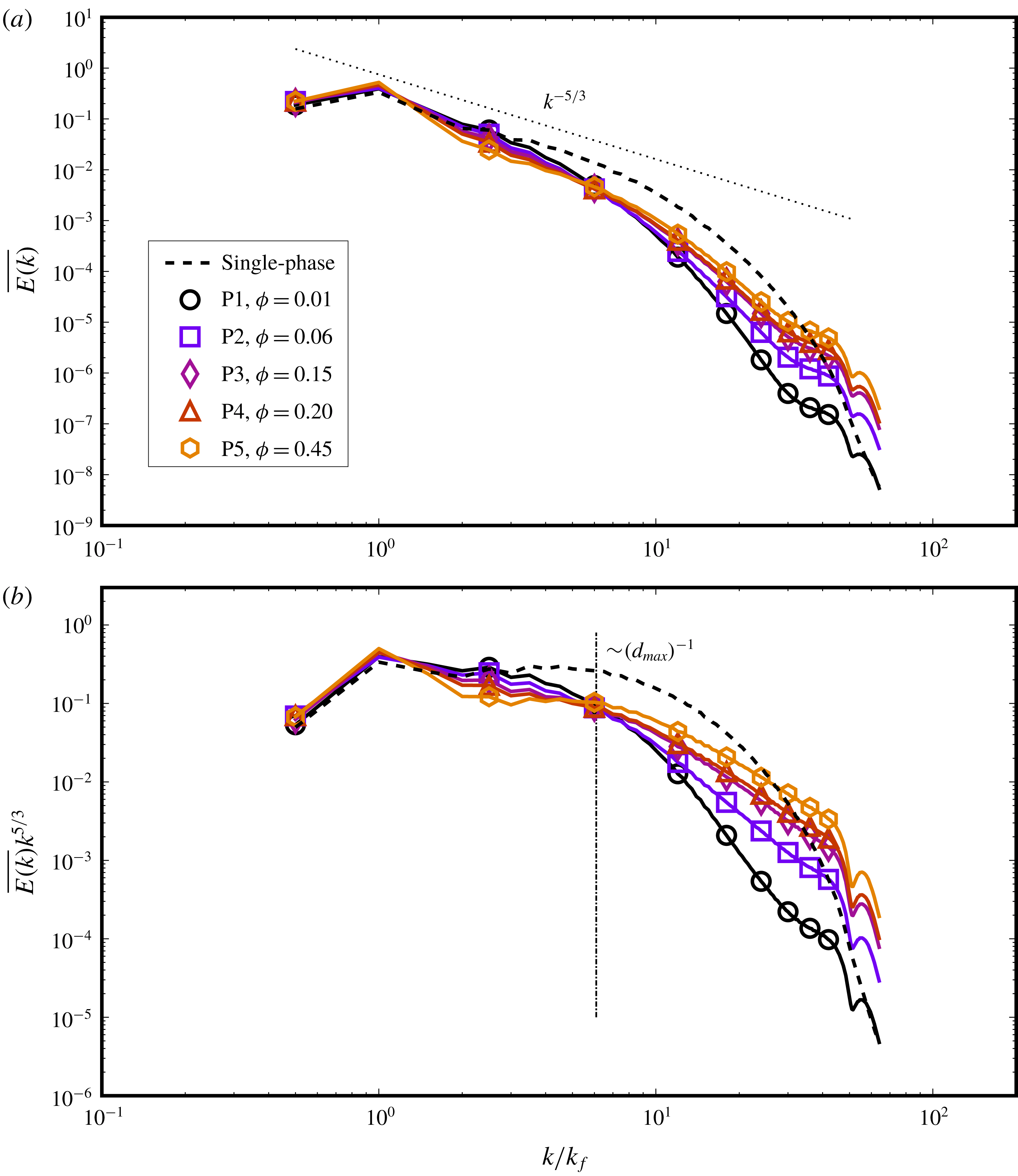
Figure 10. Kinetic energy spectra are shown in panel (a), which are obtained from varying
 $\unicode[STIX]{x1D719}$
simulations, i.e. P1–P5 (averaged between
$\unicode[STIX]{x1D719}$
simulations, i.e. P1–P5 (averaged between
 $75\unicode[STIX]{x1D70F}_{k}$
and
$75\unicode[STIX]{x1D70F}_{k}$
and
 $100\unicode[STIX]{x1D70F}_{k}$
, sampled every
$100\unicode[STIX]{x1D70F}_{k}$
, sampled every
 $2\unicode[STIX]{x1D70F}_{k}$
), where
$2\unicode[STIX]{x1D70F}_{k}$
), where
 $\overline{E(k)}=E(k)/\sum _{k}E(k)$
. At higher
$\overline{E(k)}=E(k)/\sum _{k}E(k)$
. At higher
 $\unicode[STIX]{x1D719}$
values, the turbulence cascade is suppressed at intermediate wavenumbers (seen as deviations from Kolmogorov’s
$\unicode[STIX]{x1D719}$
values, the turbulence cascade is suppressed at intermediate wavenumbers (seen as deviations from Kolmogorov’s
 $k^{-5/3}$
scaling). Panel (b) shows the compensated spectra, where the trends can be seen more clearly. At higher wavenumbers, droplet coalescence adds kinetic energy to the smaller scales, which is stronger at higher
$k^{-5/3}$
scaling). Panel (b) shows the compensated spectra, where the trends can be seen more clearly. At higher wavenumbers, droplet coalescence adds kinetic energy to the smaller scales, which is stronger at higher
 $\unicode[STIX]{x1D719}$
values due a higher chance of coalescence in a dense dispersion. The vertical line in panel (b) corresponds approximately to the inverse of the Hinze scale.
$\unicode[STIX]{x1D719}$
values due a higher chance of coalescence in a dense dispersion. The vertical line in panel (b) corresponds approximately to the inverse of the Hinze scale.
Figure 10 shows the kinetic energy spectra in (a) for the droplet-laden simulations, in comparison to the single-phase turbulence simulation with identical forcing. The first effect to note is the suppression of the inertial range (i.e. deviation from the
 $k^{-5/3}$
law) which is seen more clearly in the compensated spectra shown in (b), which is an effect that has also been found previously (Perlekar et al.
Reference Perlekar, Benzi, Clercx, Nelson and Toschi2014). For increasing
$k^{-5/3}$
law) which is seen more clearly in the compensated spectra shown in (b), which is an effect that has also been found previously (Perlekar et al.
Reference Perlekar, Benzi, Clercx, Nelson and Toschi2014). For increasing
 $\unicode[STIX]{x1D719}$
, the spectra between
$\unicode[STIX]{x1D719}$
, the spectra between
 $1<k/k_{f}<10$
shift away from the inertial range scaling and the single-phase spectrum, which shows that the cascading mechanism becomes weaker. This happens due to frequent coalescence at higher
$1<k/k_{f}<10$
shift away from the inertial range scaling and the single-phase spectrum, which shows that the cascading mechanism becomes weaker. This happens due to frequent coalescence at higher
 $\unicode[STIX]{x1D719}$
, which leads to the formation of larger droplets that can interact directly with larger inertial range scales, redirecting the kinetic energy from its cascading process into droplet deformations and breakup. Interestingly, the spectra pass through a single point, which is marked by the vertical line in (b). This point is very close to the inverse of the Hinze lengthscale given by
$\unicode[STIX]{x1D719}$
, which leads to the formation of larger droplets that can interact directly with larger inertial range scales, redirecting the kinetic energy from its cascading process into droplet deformations and breakup. Interestingly, the spectra pass through a single point, which is marked by the vertical line in (b). This point is very close to the inverse of the Hinze lengthscale given by
 $d_{max}=0.725(\unicode[STIX]{x1D70C}/\unicode[STIX]{x1D6FE})^{-3/5}\unicode[STIX]{x1D716}^{-2/5}$
. Since
$d_{max}=0.725(\unicode[STIX]{x1D70C}/\unicode[STIX]{x1D6FE})^{-3/5}\unicode[STIX]{x1D716}^{-2/5}$
. Since
 $\unicode[STIX]{x1D716}$
varies slightly among cases P1–P5, so does
$\unicode[STIX]{x1D716}$
varies slightly among cases P1–P5, so does
 $d_{max}$
(within
$d_{max}$
(within
 $5\,\%$
), which is why we indicate the length as
$5\,\%$
), which is why we indicate the length as
 ${\sim}d_{max}$
in figure 10(b).
${\sim}d_{max}$
in figure 10(b).
Beyond the inverse Hinze scale, the higher
 $\unicode[STIX]{x1D719}$
simulations contain higher energy at the smaller scales (large wavenumbers). This is due to coalescence, which generates small-scale eddies, and is more frequent at higher
$\unicode[STIX]{x1D719}$
simulations contain higher energy at the smaller scales (large wavenumbers). This is due to coalescence, which generates small-scale eddies, and is more frequent at higher
 $\unicode[STIX]{x1D719}$
. Two or more droplets coalescing add kinetic energy to the flow by loss of surface energy due to a reduction in overall surface area. The
$\unicode[STIX]{x1D719}$
. Two or more droplets coalescing add kinetic energy to the flow by loss of surface energy due to a reduction in overall surface area. The
 $\unicode[STIX]{x1D719}=0.01$
simulation has the lowest energy at high wavenumbers, as coalescence events are rare, and the droplet sizes are smaller, which in turn derive energy from eddies corresponding to slightly higher wavenumbers. While the spectra reflect these effects, they do not give any insight into the direction of the energy cascade. It would be interesting to study the effect of droplets on spectral energy transfer across scales, using the approach given by for instance Alexakis & Biferale (Reference Alexakis and Biferale2018), which would allow one to quantify the scale-dependent cascade direction, which we leave for future work. The crossover of the multiphase spectra (for
$\unicode[STIX]{x1D719}=0.01$
simulation has the lowest energy at high wavenumbers, as coalescence events are rare, and the droplet sizes are smaller, which in turn derive energy from eddies corresponding to slightly higher wavenumbers. While the spectra reflect these effects, they do not give any insight into the direction of the energy cascade. It would be interesting to study the effect of droplets on spectral energy transfer across scales, using the approach given by for instance Alexakis & Biferale (Reference Alexakis and Biferale2018), which would allow one to quantify the scale-dependent cascade direction, which we leave for future work. The crossover of the multiphase spectra (for
 $\unicode[STIX]{x1D719}\geqslant 0.15$
cases) with the single-phase spectrum shows that the dissipation range has higher energy in the presence of droplets, as was also reported by Perlekar et al. (Reference Perlekar, Benzi, Clercx, Nelson and Toschi2014). Interestingly, Ten Cate et al. (Reference Ten Cate, Derksen, Portela and Van den Akker2004) also found such a spectral crossover at increasing volume fractions for solid spherical particles in turbulence.
$\unicode[STIX]{x1D719}\geqslant 0.15$
cases) with the single-phase spectrum shows that the dissipation range has higher energy in the presence of droplets, as was also reported by Perlekar et al. (Reference Perlekar, Benzi, Clercx, Nelson and Toschi2014). Interestingly, Ten Cate et al. (Reference Ten Cate, Derksen, Portela and Van den Akker2004) also found such a spectral crossover at increasing volume fractions for solid spherical particles in turbulence.
Lastly, a small jump in the spectra at
 $k/k_{f}\approx 50$
is consistently seen for all cases, which corresponds precisely with the interface width in our simulations (i.e. 5–6 [lu]). The extra energy there is due to the spurious currents present in the system, which are found to be much weaker than the physical velocity scales. Komrakova et al. (Reference Komrakova, Eskin and Derksen2015a
) reported that spurious currents completely dominated the higher wavenumbers of the kinetic energy spectra in their turbulent dispersion simulations, due to which the spectra could not be well represented. Our work does not suffer from this problem, and although spurious currents are present, they do not adversely influence our results.
$k/k_{f}\approx 50$
is consistently seen for all cases, which corresponds precisely with the interface width in our simulations (i.e. 5–6 [lu]). The extra energy there is due to the spurious currents present in the system, which are found to be much weaker than the physical velocity scales. Komrakova et al. (Reference Komrakova, Eskin and Derksen2015a
) reported that spurious currents completely dominated the higher wavenumbers of the kinetic energy spectra in their turbulent dispersion simulations, due to which the spectra could not be well represented. Our work does not suffer from this problem, and although spurious currents are present, they do not adversely influence our results.
4.7 Generalized Hinze scale and Weber number spectra
The derivation of the Hinze scale is under the assumption of a developed inertial range and is taken to hold for dilute suspensions without coalescence. The inertial range scaling can be found for a small range of wavenumbers for simulations P1 and P2 (
 $\unicode[STIX]{x1D719}=0.01,0.06$
) which are relatively dilute, have infrequent coalescence and contain droplets that are smaller than the largest inertial range scales. For these cases, the assumptions of Hinze (Reference Hinze1955) are reasonably well approximated.
$\unicode[STIX]{x1D719}=0.01,0.06$
) which are relatively dilute, have infrequent coalescence and contain droplets that are smaller than the largest inertial range scales. For these cases, the assumptions of Hinze (Reference Hinze1955) are reasonably well approximated.
If a large amount of the dispersed phase is present, and turbulent shear cannot overcome surface tension to cause large droplets to fragment into (on an average) smaller droplets, the droplet lengthscale can be large. At larger
 $\unicode[STIX]{x1D719}$
, coalescence becomes significant as well. In these cases, there is a deviation from the
$\unicode[STIX]{x1D719}$
, coalescence becomes significant as well. In these cases, there is a deviation from the
 $k^{-5/3}$
inertial scaling (simulations P3–P5). This is because the large droplets can directly extract kinetic energy from the larger inertial range scales of flow into deformation and breakup energy, which in turn hinders the cascading mechanism. Whether this happens depends on the ratio of inertial to surface tension forces, i.e. the Weber number. For instance, the
$k^{-5/3}$
inertial scaling (simulations P3–P5). This is because the large droplets can directly extract kinetic energy from the larger inertial range scales of flow into deformation and breakup energy, which in turn hinders the cascading mechanism. Whether this happens depends on the ratio of inertial to surface tension forces, i.e. the Weber number. For instance, the
 $k^{-5/3}$
scaling is found again for simulation T5, where
$k^{-5/3}$
scaling is found again for simulation T5, where
 $\unicode[STIX]{x1D719}=0.10$
,
$\unicode[STIX]{x1D719}=0.10$
,
 $Re_{\unicode[STIX]{x1D706}}=91$
and
$Re_{\unicode[STIX]{x1D706}}=91$
and
 $\unicode[STIX]{x1D6FE}=0.04$
. In this case, the largest droplet sizes correspond to scales in the middle of the inertial range, such that a small range of wavenumbers exhibit the
$\unicode[STIX]{x1D6FE}=0.04$
. In this case, the largest droplet sizes correspond to scales in the middle of the inertial range, such that a small range of wavenumbers exhibit the
 $k^{-5/3}$
scaling, similar to simulation P1, which is shown in figure 11.
$k^{-5/3}$
scaling, similar to simulation P1, which is shown in figure 11.
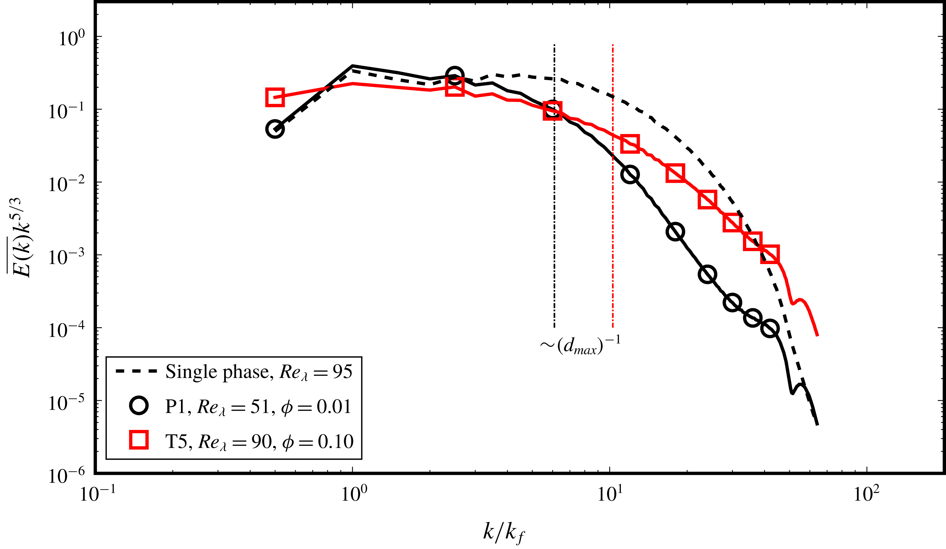
Figure 11. Compensated spectra for cases P1 and T5 showing the presence of an inertial range.
Generally, at higher volume fractions, the Hinze scale is not expected to be valid due to frequent coalescence. Even without coalescence, droplet–eddy interactions become hindered due to the presence of multiple droplets. Another lengthscale becomes important in such cases, which is the inter-droplet spacing which scales as
 $\unicode[STIX]{x0394}x\propto \unicode[STIX]{x1D719}^{-1/3}d$
. Even at seemingly low volume fractions, say
$\unicode[STIX]{x0394}x\propto \unicode[STIX]{x1D719}^{-1/3}d$
. Even at seemingly low volume fractions, say
 $\unicode[STIX]{x1D719}=0.10$
, the inter-droplet spacing is of the order of two droplet radii, due to which the dilute suspension assumption breaks down. One can, however, still consider a critical Weber number at a lengthscale
$\unicode[STIX]{x1D719}=0.10$
, the inter-droplet spacing is of the order of two droplet radii, due to which the dilute suspension assumption breaks down. One can, however, still consider a critical Weber number at a lengthscale
 $d_{max}$
, such that on average, at larger lengthscales breakup dynamics will dominate, and at lower lengthscales coalescence will dominate. This was also the original idea of Hinze, where the critical Weber number was described using the velocity scale at length
$d_{max}$
, such that on average, at larger lengthscales breakup dynamics will dominate, and at lower lengthscales coalescence will dominate. This was also the original idea of Hinze, where the critical Weber number was described using the velocity scale at length
 $d$
arising from Kolmogorov’s theory,
$d$
arising from Kolmogorov’s theory,
 $u_{d}\sim \langle \unicode[STIX]{x1D716}\rangle ^{1/3}d^{1/3}$
, as
$u_{d}\sim \langle \unicode[STIX]{x1D716}\rangle ^{1/3}d^{1/3}$
, as
 $$\begin{eqnarray}We_{crit}=\frac{\unicode[STIX]{x1D70C}u_{d}^{2}d}{\unicode[STIX]{x1D6FE}}.\end{eqnarray}$$
The use of
 $\langle \unicode[STIX]{x1D716}\rangle$
is merely to express the velocity at a given scale, under the condition that power input is balanced by the energy dissipation and the inertial scales only transfer energy without dissipating it (basically the theory of Kolmogorov (Reference Kolmogorov1941)). Since the power input is generally known, this allows an estimation of the typical droplet sizes that will arise in a dispersion. Since in high volume fraction simulations (P3–P5) the Kolmogorov (Reference Kolmogorov1941) scaling does not hold, only
$\langle \unicode[STIX]{x1D716}\rangle$
is merely to express the velocity at a given scale, under the condition that power input is balanced by the energy dissipation and the inertial scales only transfer energy without dissipating it (basically the theory of Kolmogorov (Reference Kolmogorov1941)). Since the power input is generally known, this allows an estimation of the typical droplet sizes that will arise in a dispersion. Since in high volume fraction simulations (P3–P5) the Kolmogorov (Reference Kolmogorov1941) scaling does not hold, only
 $\langle \unicode[STIX]{x1D716}\rangle$
and
$\langle \unicode[STIX]{x1D716}\rangle$
and
 $d$
alone cannot be used to determine
$d$
alone cannot be used to determine
 $u_{d}$
. The power input now is balanced in part by dissipation and in part by the changes in interfacial energy, while the dynamics of the ‘intermediate’ (that would usually be called ‘inertial’) range of scales is more complex. We propose an alternative scaling to determine
$u_{d}$
. The power input now is balanced in part by dissipation and in part by the changes in interfacial energy, while the dynamics of the ‘intermediate’ (that would usually be called ‘inertial’) range of scales is more complex. We propose an alternative scaling to determine
 $u_{d}$
, using the multiphase kinetic energy spectra
$u_{d}$
, using the multiphase kinetic energy spectra
 $E(k)$
, which implicitly takes into account the average velocity dynamics at lengthscale
$E(k)$
, which implicitly takes into account the average velocity dynamics at lengthscale
 $d$
.
$d$
.
The volume-averaged energy spectra
 $\langle E(k)\rangle$
(with units
$\langle E(k)\rangle$
(with units
 $L^{3}T^{-2}$
) and the droplet wavenumber
$L^{3}T^{-2}$
) and the droplet wavenumber
 $k_{d}=2\unicode[STIX]{x03C0}/d$
(with units
$k_{d}=2\unicode[STIX]{x03C0}/d$
(with units
 $L^{-1}$
) can be used to determine a velocity as
$L^{-1}$
) can be used to determine a velocity as
 $$\begin{eqnarray}u_{d}^{2}\sim k_{d}\langle E(k_{d})\rangle ,\end{eqnarray}$$
while other combinations of
 $k_{d}$
and
$k_{d}$
and
 $E(k_{d})$
are also possible. This velocity scale can replace that in (4.1) to calculate a Weber number spectra for all
$E(k_{d})$
are also possible. This velocity scale can replace that in (4.1) to calculate a Weber number spectra for all
 $k$
as follows:
$k$
as follows:
 $$\begin{eqnarray}We(k)=\frac{\unicode[STIX]{x1D70C}k\langle E(k)\rangle d}{\unicode[STIX]{x1D6FE}}.\end{eqnarray}$$
If the critical Weber number can be found, for instance using Lagrangian tracking as done by Perlekar et al. (Reference Perlekar, Biferale, Sbragaglia, Srivastava and Toschi2012), a generalized Hinze scale can be approximated for any form of the energy spectrum
 $E(k)$
that may arise in a multiphase system which does not obey the
$E(k)$
that may arise in a multiphase system which does not obey the
 $k^{-5/3}$
scaling and whose form may not be known a priori. Even if the critical Weber number is not quantifiable directly, an indication of the scale
$k^{-5/3}$
scaling and whose form may not be known a priori. Even if the critical Weber number is not quantifiable directly, an indication of the scale
 $k_{d}$
at which
$k_{d}$
at which
 $We\approx 1$
can be found, such that droplets at scales
$We\approx 1$
can be found, such that droplets at scales
 $k<k_{d}$
will be more prone to breakup, while droplets at scales
$k<k_{d}$
will be more prone to breakup, while droplets at scales
 $k>k_{d}$
will mostly coalesce. If we plug into (4.3) the Kolmogorov energy spectrum
$k>k_{d}$
will mostly coalesce. If we plug into (4.3) the Kolmogorov energy spectrum
 $E(k)\sim \unicode[STIX]{x1D716}^{2/3}k^{-5/3}$
, we get the term
$E(k)\sim \unicode[STIX]{x1D716}^{2/3}k^{-5/3}$
, we get the term
 $k\unicode[STIX]{x1D716}^{2/3}k^{-5/3}d$
, which gives us
$k\unicode[STIX]{x1D716}^{2/3}k^{-5/3}d$
, which gives us
 $\unicode[STIX]{x1D716}^{2/3}k^{-2/3}d\sim \unicode[STIX]{x1D716}^{2/3}(2\unicode[STIX]{x03C0}/d)^{-2/3}d\sim \unicode[STIX]{x1D716}^{2/3}d^{5/3}$
(to within multiplicative constants). Solving this equation for
$\unicode[STIX]{x1D716}^{2/3}k^{-2/3}d\sim \unicode[STIX]{x1D716}^{2/3}(2\unicode[STIX]{x03C0}/d)^{-2/3}d\sim \unicode[STIX]{x1D716}^{2/3}d^{5/3}$
(to within multiplicative constants). Solving this equation for
 $d$
, for a known critical Weber number, yields the classical Hinze scale
$d$
, for a known critical Weber number, yields the classical Hinze scale
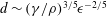 $d\sim (\unicode[STIX]{x1D6FE}/\unicode[STIX]{x1D70C})^{3/5}\unicode[STIX]{x1D716}^{-2/5}$
. Hence (4.3) can be treated as a generalization of the Hinze scale, applicable to dense and dilute suspensions alike.
$d\sim (\unicode[STIX]{x1D6FE}/\unicode[STIX]{x1D70C})^{3/5}\unicode[STIX]{x1D716}^{-2/5}$
. Hence (4.3) can be treated as a generalization of the Hinze scale, applicable to dense and dilute suspensions alike.
In figure 12, the Weber number spectra as given by (4.3) are shown for cases P3–P5, which were sufficiently dense suspensions for the chosen
 $Re_{\unicode[STIX]{x1D706}}$
such that the inertial range scaling is affected by the dispersed phase. A range of wavenumbers gives
$Re_{\unicode[STIX]{x1D706}}$
such that the inertial range scaling is affected by the dispersed phase. A range of wavenumbers gives
 $We>1$
, which should correspond to breakup-dominated scales. Case P3 is shown in the inset, where we have
$We>1$
, which should correspond to breakup-dominated scales. Case P3 is shown in the inset, where we have
 $We=1$
at
$We=1$
at
 $k/k_{f}=2.5$
, i.e.
$k/k_{f}=2.5$
, i.e.
 $k=5$
. This corresponds to a droplet scale of around
$k=5$
. This corresponds to a droplet scale of around
 $d\approx 50~[\text{lu}]$
. From figure 9(c), we see that the droplet distribution begins to fall off with the
$d\approx 50~[\text{lu}]$
. From figure 9(c), we see that the droplet distribution begins to fall off with the
 $d^{-10/3}$
slope around
$d^{-10/3}$
slope around
 $d/\unicode[STIX]{x1D702}\approx 30$
, which gives
$d/\unicode[STIX]{x1D702}\approx 30$
, which gives
 $d\approx 45~[\text{lu}]$
. These two values are of the same order, which shows that the unstable scale prediction from the Weber spectrum well approximates the cutoff droplet scale
$d\approx 45~[\text{lu}]$
. These two values are of the same order, which shows that the unstable scale prediction from the Weber spectrum well approximates the cutoff droplet scale
 $k_{d}$
, such that in the range
$k_{d}$
, such that in the range
 $k>k_{d}$
, droplets can be expected to predominantly undergo breakup (the
$k>k_{d}$
, droplets can be expected to predominantly undergo breakup (the
 $d^{-10/3}$
regime), while in the
$d^{-10/3}$
regime), while in the
 $k<k_{d}$
range droplets are stable (the
$k<k_{d}$
range droplets are stable (the
 $d^{-3/2}$
regime). Deane & Stokes (Reference Deane and Stokes2002) also refer to the scale at which they observed this transition between the two scaling regimes to be the critical (Hinze) scale.
$d^{-3/2}$
regime). Deane & Stokes (Reference Deane and Stokes2002) also refer to the scale at which they observed this transition between the two scaling regimes to be the critical (Hinze) scale.
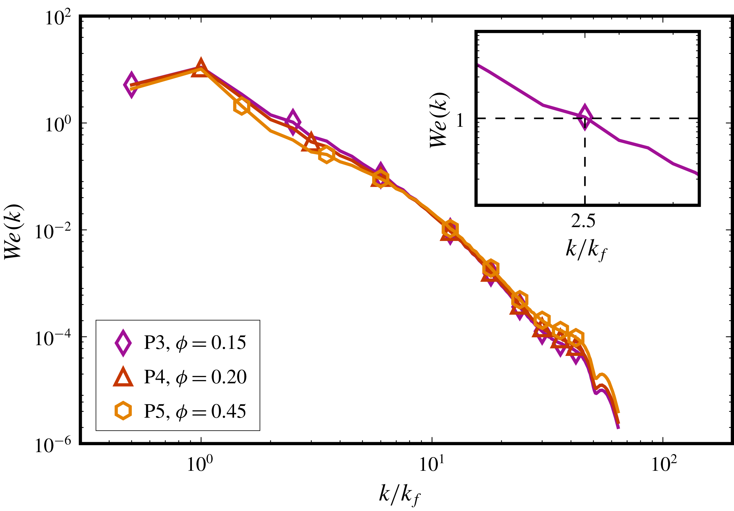
Figure 12. Weber spectrum
 $We(k)$
for cases P3–P5, along with a close look (inset) at case P3 near
$We(k)$
for cases P3–P5, along with a close look (inset) at case P3 near
 $We=1$
, which occurs at
$We=1$
, which occurs at
 $k/k_{f}=2.5$
, which closely corresponds to the scale at which there is a transition in the droplet distribution power-law slopes (figure 9
c,d).
$k/k_{f}=2.5$
, which closely corresponds to the scale at which there is a transition in the droplet distribution power-law slopes (figure 9
c,d).
4.8 Effect of turbulence intensity
As mentioned earlier, the idea behind applying turbulence is to cause fragmentation of the dispersed phase, and the number of droplets thus formed depends upon the intensity of turbulence. We now keep the volume fraction fixed at
 $\unicode[STIX]{x1D719}=0.1$
and increase the turbulence intensity by increasing the forcing amplitude. These are simulations T1–T5 in table 1, and are run for
$\unicode[STIX]{x1D719}=0.1$
and increase the turbulence intensity by increasing the forcing amplitude. These are simulations T1–T5 in table 1, and are run for
 $t=0.5$
million time steps each, though the simulations will have different
$t=0.5$
million time steps each, though the simulations will have different
 $\unicode[STIX]{x1D70F}_{k}$
. Figure 13 shows the evolution of the normalized phase fraction over time, and as expected, at higher turbulence intensities (which leads to a higher
$\unicode[STIX]{x1D70F}_{k}$
. Figure 13 shows the evolution of the normalized phase fraction over time, and as expected, at higher turbulence intensities (which leads to a higher
 $Re_{\unicode[STIX]{x1D706}}$
),
$Re_{\unicode[STIX]{x1D706}}$
),
 $\unicode[STIX]{x1D719}/\unicode[STIX]{x1D719}_{0}$
reduces over time to an individual stable value. In case T4, all the droplets dissolve within
$\unicode[STIX]{x1D719}/\unicode[STIX]{x1D719}_{0}$
reduces over time to an individual stable value. In case T4, all the droplets dissolve within
 $600\unicode[STIX]{x1D70F}_{k}$
, which shows that for this combination of parameters (refer to table 1), turbulence forcing undesirably outclasses the PP-LB phase segregation. The small droplets formed in this system are subsequently unstable (due to
$600\unicode[STIX]{x1D70F}_{k}$
, which shows that for this combination of parameters (refer to table 1), turbulence forcing undesirably outclasses the PP-LB phase segregation. The small droplets formed in this system are subsequently unstable (due to
 $Ch\sim O(1)$
), which causes complete dissolution of the dispersed phase. Upon increasing the liquid–liquid repulsion parameter
$Ch\sim O(1)$
), which causes complete dissolution of the dispersed phase. Upon increasing the liquid–liquid repulsion parameter
 $G_{\unicode[STIX]{x1D6FC}\unicode[STIX]{x1D6FD}}$
(hence also changing the fluid composition and dimensionless numbers that include interfacial tension, like the Weber or Ohnesorge number) in case T5, we see that for the same turbulence intensity as case T4,
$G_{\unicode[STIX]{x1D6FC}\unicode[STIX]{x1D6FD}}$
(hence also changing the fluid composition and dimensionless numbers that include interfacial tension, like the Weber or Ohnesorge number) in case T5, we see that for the same turbulence intensity as case T4,
 $\unicode[STIX]{x1D719}/\unicode[STIX]{x1D719}_{0}$
remains stable. This reaffirms that with the original PP-LB method certain regions of the turbulent emulsions parameter space can be simulated on a given mesh size, while in other cases (case T4 and to some degree also case T3) simulations may require additional numerical remedies like the mass correction scheme of Biferale et al. (Reference Biferale, Perlekar, Sbragaglia, Srivastava and Toschi2011) and Perlekar et al. (Reference Perlekar, Biferale, Sbragaglia, Srivastava and Toschi2012) or an enhanced Kolmogorov scale resolution (to achieve higher Cahn numbers) as done by Komrakova et al. (Reference Komrakova, Eskin and Derksen2015a
). We now briefly demonstrate the latter method.
$\unicode[STIX]{x1D719}/\unicode[STIX]{x1D719}_{0}$
remains stable. This reaffirms that with the original PP-LB method certain regions of the turbulent emulsions parameter space can be simulated on a given mesh size, while in other cases (case T4 and to some degree also case T3) simulations may require additional numerical remedies like the mass correction scheme of Biferale et al. (Reference Biferale, Perlekar, Sbragaglia, Srivastava and Toschi2011) and Perlekar et al. (Reference Perlekar, Biferale, Sbragaglia, Srivastava and Toschi2012) or an enhanced Kolmogorov scale resolution (to achieve higher Cahn numbers) as done by Komrakova et al. (Reference Komrakova, Eskin and Derksen2015a
). We now briefly demonstrate the latter method.
Figure 13. Evolution of the relative volume fraction
 $\unicode[STIX]{x1D719}/\unicode[STIX]{x1D719}_{0}$
for varying turbulence intensity simulations (cases T1–T5 in table 1). Increasing
$\unicode[STIX]{x1D719}/\unicode[STIX]{x1D719}_{0}$
for varying turbulence intensity simulations (cases T1–T5 in table 1). Increasing
 $Re_{\unicode[STIX]{x1D706}}$
causes greater droplet dissolution leading to a lower settling value of
$Re_{\unicode[STIX]{x1D706}}$
causes greater droplet dissolution leading to a lower settling value of
 $\unicode[STIX]{x1D719}/\unicode[STIX]{x1D719}_{0}$
. This effect limits the parameter space that can be simulated with the original PP-LB method, as shown by cases T4 and T5.
$\unicode[STIX]{x1D719}/\unicode[STIX]{x1D719}_{0}$
. This effect limits the parameter space that can be simulated with the original PP-LB method, as shown by cases T4 and T5.
4.9 Decreasing the Cahn number to control droplet dissolution
The Cahn number for a simulation can be decreased by increasing the domain size
 $N_{x}$
, while the turbulence intensity and energy injection scale (forcing wavenumber) are kept the same. In this case, the Kolmogorov scale
$N_{x}$
, while the turbulence intensity and energy injection scale (forcing wavenumber) are kept the same. In this case, the Kolmogorov scale
 $\unicode[STIX]{x1D702}$
increases because the separation between the energy injection scale
$\unicode[STIX]{x1D702}$
increases because the separation between the energy injection scale
 ${\mathcal{L}}$
and the dissipation scale
${\mathcal{L}}$
and the dissipation scale
 $\unicode[STIX]{x1D702}$
remains fixed, while
$\unicode[STIX]{x1D702}$
remains fixed, while
 ${\mathcal{L}}$
increases. Since the interface width
${\mathcal{L}}$
increases. Since the interface width
 $\unicode[STIX]{x1D701}$
remains unchanged, and the droplet size
$\unicode[STIX]{x1D701}$
remains unchanged, and the droplet size
 $d$
increases,
$d$
increases,
 $\unicode[STIX]{x1D701}/d$
decreases. The shrinkage and dissolution of droplets occurs due to the slow diffusion process, which has a timescale
$\unicode[STIX]{x1D701}/d$
decreases. The shrinkage and dissolution of droplets occurs due to the slow diffusion process, which has a timescale
 $\unicode[STIX]{x1D70F}_{d}\propto N_{x}^{2}$
. Hence decreasing the Cahn number has two effects which together reduce droplet dissolution. The first is that a larger domain size leads to a higher
$\unicode[STIX]{x1D70F}_{d}\propto N_{x}^{2}$
. Hence decreasing the Cahn number has two effects which together reduce droplet dissolution. The first is that a larger domain size leads to a higher
 $\unicode[STIX]{x1D70F}_{d}$
, which can be made sufficiently larger than the flow timescale
$\unicode[STIX]{x1D70F}_{d}$
, which can be made sufficiently larger than the flow timescale
 ${\mathcal{T}}$
such that the slow mass diffusion does not influence the results. Secondly, since on average the droplets are larger, there will be fewer small droplets that are unstable and prone to dissolution.
${\mathcal{T}}$
such that the slow mass diffusion does not influence the results. Secondly, since on average the droplets are larger, there will be fewer small droplets that are unstable and prone to dissolution.

Figure 14. Decreasing the Cahn number is shown to reduce droplet dissolution. Simulation T3 is performed again on a larger domain (i.e. simulation T3R), while keeping the energy density the same, as shown in (a). Panel (b) shows the volume fraction evolution for the two simulations. The droplet dissolution effect is lower in T3R and the stable
 $\unicode[STIX]{x1D719}$
value is a factor
$\unicode[STIX]{x1D719}$
value is a factor
 $2$
higher than T3. Upon scaling time with the square of the domain size, the two curves collapse for the initial droplet dissolution phase until steady state is reached. Lower droplet dissolution is an effect of increased separation between the flow timescale and component diffusion timescale (as shown in the inset of (b), where
$2$
higher than T3. Upon scaling time with the square of the domain size, the two curves collapse for the initial droplet dissolution phase until steady state is reached. Lower droplet dissolution is an effect of increased separation between the flow timescale and component diffusion timescale (as shown in the inset of (b), where
 $\unicode[STIX]{x1D719}$
reduces at a slower rate for T3R).
$\unicode[STIX]{x1D719}$
reduces at a slower rate for T3R).
Simulations T3 and T4 suffer most strongly from droplet dissolution, so we test how increasing the resolution of these simulations can reduce this effect. Figure 14 shows a comparison between simulations T3 and T3R. Panel (a) shows that the two simulations have very similar average kinetic energy
 $\langle E_{k}\rangle$
and enstrophy
$\langle E_{k}\rangle$
and enstrophy
 $\langle \unicode[STIX]{x1D714}^{2}\rangle$
, although
$\langle \unicode[STIX]{x1D714}^{2}\rangle$
, although
 $\langle \unicode[STIX]{x1D714}^{2}\rangle$
is found to be slightly lower in T3R which leads to slightly higher
$\langle \unicode[STIX]{x1D714}^{2}\rangle$
is found to be slightly lower in T3R which leads to slightly higher
 $Re_{\unicode[STIX]{x1D706}}$
in T3R than in T3. This is because with the current formulation of the turbulence forcing mechanism it is not possible to exactly set the
$Re_{\unicode[STIX]{x1D706}}$
in T3R than in T3. This is because with the current formulation of the turbulence forcing mechanism it is not possible to exactly set the
 $Re_{\unicode[STIX]{x1D706}}$
of the simulation and it depends on the forcing amplitude
$Re_{\unicode[STIX]{x1D706}}$
of the simulation and it depends on the forcing amplitude
 $A$
. Despite this difference, the higher resolution of T3R leads to less droplet dissolution as seen from (b). Upon non-dimensionalizing time with the domain size
$A$
. Despite this difference, the higher resolution of T3R leads to less droplet dissolution as seen from (b). Upon non-dimensionalizing time with the domain size
 $N_{x}$
, the initial reductions in
$N_{x}$
, the initial reductions in
 $\unicode[STIX]{x1D719}$
for T3 and T3R overlap, which shows that the diffusive mass redistribution occurs over a longer timescale proportional to
$\unicode[STIX]{x1D719}$
for T3 and T3R overlap, which shows that the diffusive mass redistribution occurs over a longer timescale proportional to
 $N_{x}^{2}$
. In non-dimensional units, these physically long duration simulations over
$N_{x}^{2}$
. In non-dimensional units, these physically long duration simulations over
 $1000\unicode[STIX]{x1D70F}_{k}$
are well within
$1000\unicode[STIX]{x1D70F}_{k}$
are well within
 $10^{-2}$
diffusive time units, showing that the timescale of flow is much faster. Further, T3R has a higher
$10^{-2}$
diffusive time units, showing that the timescale of flow is much faster. Further, T3R has a higher
 $\unicode[STIX]{x1D719}$
value at steady state, where droplet dissolution is reduced from
$\unicode[STIX]{x1D719}$
value at steady state, where droplet dissolution is reduced from
 $80\,\%$
to
$80\,\%$
to
 $50\,\%$
. This is an indication that fewer droplets with
$50\,\%$
. This is an indication that fewer droplets with
 $Ch\sim O(1)$
are formed. The inset in (b) shows the evolution of
$Ch\sim O(1)$
are formed. The inset in (b) shows the evolution of
 $\unicode[STIX]{x1D719}$
over time non-dimensionalized with
$\unicode[STIX]{x1D719}$
over time non-dimensionalized with
 $\unicode[STIX]{x1D70F}_{k}$
. The steady-state
$\unicode[STIX]{x1D70F}_{k}$
. The steady-state
 $\unicode[STIX]{x1D719}$
is found to be achieved sooner, and at the limit of much higher resolution, diffusional mass transfer will not influence the flow. The same effect was found upon performing a refined version of simulation T4 (T4R, not shown here), where increasing the resolution from
$\unicode[STIX]{x1D719}$
is found to be achieved sooner, and at the limit of much higher resolution, diffusional mass transfer will not influence the flow. The same effect was found upon performing a refined version of simulation T4 (T4R, not shown here), where increasing the resolution from
 $256^{3}$
to
$256^{3}$
to
 $384^{3}$
reduced droplet dissolution from
$384^{3}$
reduced droplet dissolution from
 $100\,\%$
to about
$100\,\%$
to about
 $80\,\%$
. We omit cases T3 and T4 from further analysis due to severe droplet dissolution.
$80\,\%$
. We omit cases T3 and T4 from further analysis due to severe droplet dissolution.
4.10 Droplet number density evolution
Figure 15 shows the evolution of the number of droplets for cases T1, T2 and T5. Increasing
 $Re_{\unicode[STIX]{x1D706}}$
increases the average number of droplets in the system (obtained by averaging
$Re_{\unicode[STIX]{x1D706}}$
increases the average number of droplets in the system (obtained by averaging
 $N_{d}$
after steady-state conditions are reached for each simulation) from around
$N_{d}$
after steady-state conditions are reached for each simulation) from around
 $\overline{N_{d}}=50$
for
$\overline{N_{d}}=50$
for
 $Re_{\unicode[STIX]{x1D706}}=44$
to
$Re_{\unicode[STIX]{x1D706}}=44$
to
 $\overline{N_{d}}=600$
for
$\overline{N_{d}}=600$
for
 $Re_{\unicode[STIX]{x1D706}}=90$
. Further, two interesting features in the evolution of
$Re_{\unicode[STIX]{x1D706}}=90$
. Further, two interesting features in the evolution of
 $N_{d}$
can be noted. The first is that the variation in
$N_{d}$
can be noted. The first is that the variation in
 $N_{d}$
increases with
$N_{d}$
increases with
 $Re_{\unicode[STIX]{x1D706}}$
, which results in a larger standard deviation of
$Re_{\unicode[STIX]{x1D706}}$
, which results in a larger standard deviation of
 $\overline{N_{d}}$
. This also makes it possible to generate a wider distribution of droplet diameters in the system, due to higher intermittency (Garrett et al.
Reference Garrett, Li and Farmer2000). The second striking feature is the quasi-periodic rise and fall in the droplet number concentration (with a period of around
$\overline{N_{d}}$
. This also makes it possible to generate a wider distribution of droplet diameters in the system, due to higher intermittency (Garrett et al.
Reference Garrett, Li and Farmer2000). The second striking feature is the quasi-periodic rise and fall in the droplet number concentration (with a period of around
 $8{\mathcal{T}}$
–
$8{\mathcal{T}}$
–
 $10{\mathcal{T}}$
), most distinctly seen for the
$10{\mathcal{T}}$
), most distinctly seen for the
 $Re_{\unicode[STIX]{x1D706}}=90$
simulation (case T5). There seems to be an upper limit to the number of droplets that can be formed which, apart from constraints of resolution and maximum sphere packing of the domain while keeping the diffuse interfaces apart, indicates also the underlying physical mechanisms. At its peak,
$Re_{\unicode[STIX]{x1D706}}=90$
simulation (case T5). There seems to be an upper limit to the number of droplets that can be formed which, apart from constraints of resolution and maximum sphere packing of the domain while keeping the diffuse interfaces apart, indicates also the underlying physical mechanisms. At its peak,
 $N_{d}\approx 900$
here, a state corresponding to most droplets being rather small that cannot undergo additional breakup as they would all be well below the Hinze scale. These droplets are advected around by the flow and they begin to coalesce when they collide, causing
$N_{d}\approx 900$
here, a state corresponding to most droplets being rather small that cannot undergo additional breakup as they would all be well below the Hinze scale. These droplets are advected around by the flow and they begin to coalesce when they collide, causing
 $N_{d}$
to drop to its lower limit, where a significant number of droplets will again be larger than the Hinze scale, and they begin to break and this cycle continues. We shall revisit this feature in detail in § 5.1.
$N_{d}$
to drop to its lower limit, where a significant number of droplets will again be larger than the Hinze scale, and they begin to break and this cycle continues. We shall revisit this feature in detail in § 5.1.
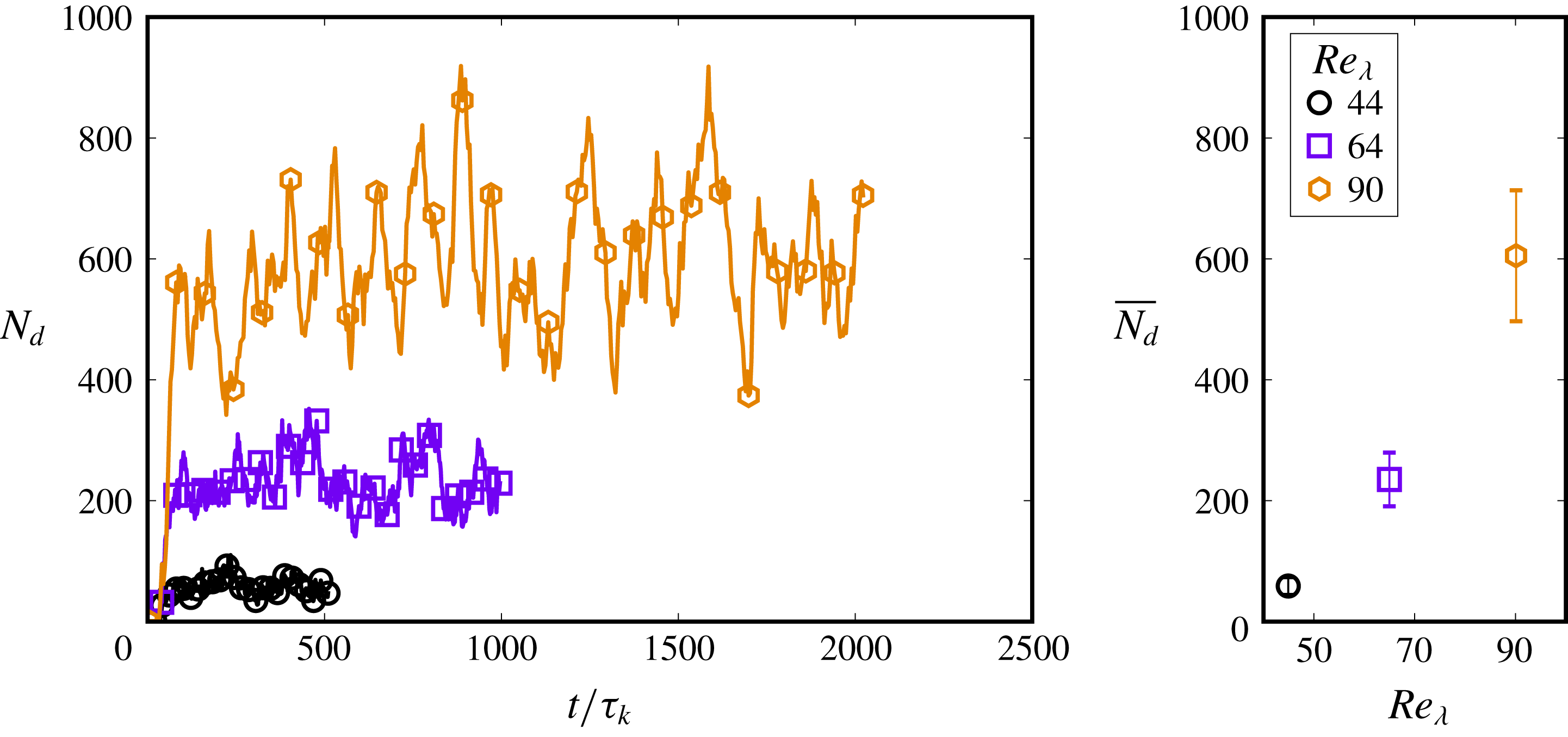
Figure 15. Evolution of the number of droplets (
 $N_{d}$
) for increasing turbulence intensity, indicated by
$N_{d}$
) for increasing turbulence intensity, indicated by
 $Re_{\unicode[STIX]{x1D706}}$
. Increasing
$Re_{\unicode[STIX]{x1D706}}$
. Increasing
 $Re_{\unicode[STIX]{x1D706}}$
leads to a larger number of droplets in the system, also widening the droplet distributions as seen from the fluctuations in the
$Re_{\unicode[STIX]{x1D706}}$
leads to a larger number of droplets in the system, also widening the droplet distributions as seen from the fluctuations in the
 $N_{d}$
evolution.
$N_{d}$
evolution.
 $\overline{N(d)}$
is obtained by averaging
$\overline{N(d)}$
is obtained by averaging
 $N(d)$
after steady-state conditions are reached.
$N(d)$
after steady-state conditions are reached.
4.11 Dispersion morphology
The dispersion morphology can be quantified with the concentration spectrum
 $k^{2}S(k,t)$
, a quantity commonly used to describe coarsening dynamics (or spinodal decomposition) (Chen et al.
Reference Chen, Boghosian, Coveney and Nekovee2000; Perlekar et al.
Reference Perlekar, Benzi, Clercx, Nelson and Toschi2014). Here
$k^{2}S(k,t)$
, a quantity commonly used to describe coarsening dynamics (or spinodal decomposition) (Chen et al.
Reference Chen, Boghosian, Coveney and Nekovee2000; Perlekar et al.
Reference Perlekar, Benzi, Clercx, Nelson and Toschi2014). Here
 $S(k,t)$
is the shell-averaged structure factor which is obtained using the Fourier transform
$S(k,t)$
is the shell-averaged structure factor which is obtained using the Fourier transform
 $\hat{\unicode[STIX]{x1D719}}_{\boldsymbol{k}}$
of the density–density correlation function
$\hat{\unicode[STIX]{x1D719}}_{\boldsymbol{k}}$
of the density–density correlation function
 $\unicode[STIX]{x1D719}-\overline{\unicode[STIX]{x1D719}}$
, where
$\unicode[STIX]{x1D719}-\overline{\unicode[STIX]{x1D719}}$
, where
 $\unicode[STIX]{x1D719}=(\unicode[STIX]{x1D70C}_{\unicode[STIX]{x1D6FC}}-\unicode[STIX]{x1D70C}_{\unicode[STIX]{x1D6FD}})$
and
$\unicode[STIX]{x1D719}=(\unicode[STIX]{x1D70C}_{\unicode[STIX]{x1D6FC}}-\unicode[STIX]{x1D70C}_{\unicode[STIX]{x1D6FD}})$
and
 $\overline{\unicode[STIX]{x1D719}}$
is the mean value of
$\overline{\unicode[STIX]{x1D719}}$
is the mean value of
 $\unicode[STIX]{x1D719}$
. The quantity
$\unicode[STIX]{x1D719}$
. The quantity
 $\hat{\unicode[STIX]{x1D719}}_{\boldsymbol{k}}$
is shell-averaged in wavenumber space to obtain
$\hat{\unicode[STIX]{x1D719}}_{\boldsymbol{k}}$
is shell-averaged in wavenumber space to obtain
 $S(k,t)$
as follows:
$S(k,t)$
as follows:
 $$\begin{eqnarray}S(k,t)=\frac{\displaystyle \mathop{\sum }_{k}|\hat{\unicode[STIX]{x1D719}}_{\boldsymbol{k}}|^{2}}{\displaystyle \mathop{\sum }_{k}1}.\end{eqnarray}$$
Here
 $\sum$
denotes summation over wavenumber shells
$\sum$
denotes summation over wavenumber shells
 $k\in [k-1/2,k+1/2]$
where
$k\in [k-1/2,k+1/2]$
where
 $k=\sqrt{\boldsymbol{k}\boldsymbol{\cdot }\boldsymbol{ k}}$
. Further, a characteristic length
$k=\sqrt{\boldsymbol{k}\boldsymbol{\cdot }\boldsymbol{ k}}$
. Further, a characteristic length
 $L(t)$
can be calculated using the first moment of
$L(t)$
can be calculated using the first moment of
 $S(k,t)$
as follows:
$S(k,t)$
as follows:
 $$\begin{eqnarray}L(t)=2\unicode[STIX]{x03C0}\frac{\displaystyle \mathop{\sum }_{k}S(k,t)}{\displaystyle \mathop{\sum }_{k}kS(k,t)}.\end{eqnarray}$$
Figure 16 shows the concentration spectrum for cases T1, T2 and T5. As
 $Re_{\unicode[STIX]{x1D706}}$
is increased, smaller droplets begin to dominate the system, which is seen from the shift towards higher wavenumbers in
$Re_{\unicode[STIX]{x1D706}}$
is increased, smaller droplets begin to dominate the system, which is seen from the shift towards higher wavenumbers in
 $k^{2}S(k,t)$
. This is also reflected in the time-averaged characteristic length
$k^{2}S(k,t)$
. This is also reflected in the time-averaged characteristic length
 $L$
which decreases from
$L$
which decreases from
 $100$
to around
$100$
to around
 $40~[\text{lu}]$
. Note, however, that T5 has a higher surface tension than T1 and T2, and it is
$40~[\text{lu}]$
. Note, however, that T5 has a higher surface tension than T1 and T2, and it is
 $\unicode[STIX]{x1D6FE}$
and
$\unicode[STIX]{x1D6FE}$
and
 $Re_{\unicode[STIX]{x1D706}}$
together that determine the morphology of the emulsion for a given dispersed-phase volume fraction.
$Re_{\unicode[STIX]{x1D706}}$
together that determine the morphology of the emulsion for a given dispersed-phase volume fraction.
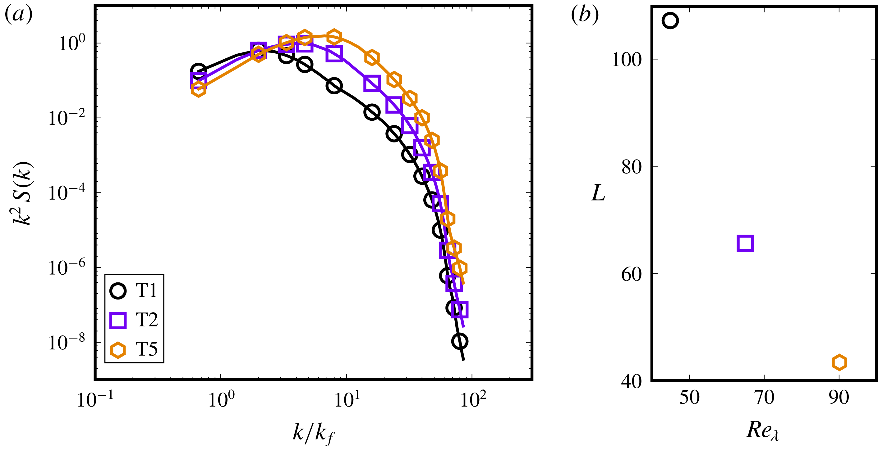
Figure 16. Concentration spectrum and characteristic length characterizing the dispersion morphology for increasing turbulence intensity simulations, corresponding to cases T1, T2 and T5 in table 1. The structure factor
 $S(k,t)$
was time averaged over 10 realizations separated by
$S(k,t)$
was time averaged over 10 realizations separated by
 ${\approx}50\unicode[STIX]{x1D70F}_{k}$
, and further normalized by
${\approx}50\unicode[STIX]{x1D70F}_{k}$
, and further normalized by
 $\sum _{k}S(k,t)$
to compare the relative difference in concentration at each wavelength. Increasing
$\sum _{k}S(k,t)$
to compare the relative difference in concentration at each wavelength. Increasing
 $Re_{\unicode[STIX]{x1D706}}$
generates smaller droplets which is seen in the reduction of the characteristic length.
$Re_{\unicode[STIX]{x1D706}}$
generates smaller droplets which is seen in the reduction of the characteristic length.
4.12 Effect of domain size
In simulations corresponding to D1–D4 in table 1, we successively increase the domain size
 $N_{x}$
while keeping the turbulent energy density the same. This essentially creates a separation between the domain size
$N_{x}$
while keeping the turbulent energy density the same. This essentially creates a separation between the domain size
 $N_{x}$
and the forcing scale
$N_{x}$
and the forcing scale
 ${\mathcal{L}}$
, and allows for a better resolution of the largest droplet extension before breakup. So far, studies on turbulent dispersions have focused on maximizing the turbulence intensity, which is reflected in the general proclivity for achieving higher
${\mathcal{L}}$
, and allows for a better resolution of the largest droplet extension before breakup. So far, studies on turbulent dispersions have focused on maximizing the turbulence intensity, which is reflected in the general proclivity for achieving higher
 $Re_{\unicode[STIX]{x1D706}}$
in DNS with Lagrangian objects like particles or droplets (Toschi & Bodenschatz Reference Toschi and Bodenschatz2009). This finds implicit justification in that
$Re_{\unicode[STIX]{x1D706}}$
in DNS with Lagrangian objects like particles or droplets (Toschi & Bodenschatz Reference Toschi and Bodenschatz2009). This finds implicit justification in that
 $Re_{\unicode[STIX]{x1D706}}$
in real systems where droplets and turbulence interact is typically very high (where
$Re_{\unicode[STIX]{x1D706}}$
in real systems where droplets and turbulence interact is typically very high (where
 $Re_{\unicode[STIX]{x1D706}}=\sqrt{15Re}$
for homogeneous isotropic turbulence). For instance, emulsification in a valve homogenizer or colloid mill can occur at
$Re_{\unicode[STIX]{x1D706}}=\sqrt{15Re}$
for homogeneous isotropic turbulence). For instance, emulsification in a valve homogenizer or colloid mill can occur at
 $Re\sim 30\,000$
(Davies Reference Davies1985; Vankova et al.
Reference Vankova, Tcholakova, Denkov, Ivanov, Vulchev and Danner2007) and emulsification in stirred vessels has been studied at
$Re\sim 30\,000$
(Davies Reference Davies1985; Vankova et al.
Reference Vankova, Tcholakova, Denkov, Ivanov, Vulchev and Danner2007) and emulsification in stirred vessels has been studied at
 $Re\sim 15\,000$
(Boxall et al.
Reference Boxall, Koh, Sloan, Sum and Wu2011) – for all these situations
$Re\sim 15\,000$
(Boxall et al.
Reference Boxall, Koh, Sloan, Sum and Wu2011) – for all these situations
 $Re_{\unicode[STIX]{x1D706}}>500$
, which is several times larger than the range considered in the current study. In periodic domain DNS, a high
$Re_{\unicode[STIX]{x1D706}}>500$
, which is several times larger than the range considered in the current study. In periodic domain DNS, a high
 $Re_{\unicode[STIX]{x1D706}}$
is achieved by minimally resolving the Kolmogorov scale (the
$Re_{\unicode[STIX]{x1D706}}$
is achieved by minimally resolving the Kolmogorov scale (the
 $k_{max}\unicode[STIX]{x1D702}>1$
condition (Moin & Mahesh Reference Moin and Mahesh1998)), while forcing turbulence at the largest possible scales, i.e.
$k_{max}\unicode[STIX]{x1D702}>1$
condition (Moin & Mahesh Reference Moin and Mahesh1998)), while forcing turbulence at the largest possible scales, i.e.
 ${\mathcal{L}}\approx N_{x}$
or
${\mathcal{L}}\approx N_{x}$
or
 $k_{f}\approx 1-2k_{min}$
. This wide separation of scales manifests a high
$k_{f}\approx 1-2k_{min}$
. This wide separation of scales manifests a high
 $Re_{\unicode[STIX]{x1D706}}$
. There are a few connected issues regarding the relative resolution of the various lengthscales, which is the focus of this section.
$Re_{\unicode[STIX]{x1D706}}$
. There are a few connected issues regarding the relative resolution of the various lengthscales, which is the focus of this section.
The first issue, emphasized by Komrakova et al. (Reference Komrakova, Eskin and Derksen2015a
), is the utility of over-resolving the Kolmogorov scale (
 $\unicode[STIX]{x1D702}\approx 10$
as opposed to
$\unicode[STIX]{x1D702}\approx 10$
as opposed to
 $1~[\text{lu}]$
), which helped remedy the rapid dissolution of droplets in their simulations. The increased resolution of
$1~[\text{lu}]$
), which helped remedy the rapid dissolution of droplets in their simulations. The increased resolution of
 $\unicode[STIX]{x1D702}$
and
$\unicode[STIX]{x1D702}$
and
 $d$
can also be seen as a reduction in the size of the interface
$d$
can also be seen as a reduction in the size of the interface
 $\unicode[STIX]{x1D701}$
, i.e. a decrease in the Cahn number
$\unicode[STIX]{x1D701}$
, i.e. a decrease in the Cahn number
 $Ch$
, since the interface thickness (in terms of the number of lattice spacings) remains constant while smaller droplets and turbulent lengthscales become better resolved (i.e. they become larger relative to
$Ch$
, since the interface thickness (in terms of the number of lattice spacings) remains constant while smaller droplets and turbulent lengthscales become better resolved (i.e. they become larger relative to
 $\unicode[STIX]{x1D701}$
). Droplet dissolution also depends on the relative strengths of turbulence and phase segregation (effectively the interfacial tension), as was demonstrated in § 4.8.
$\unicode[STIX]{x1D701}$
). Droplet dissolution also depends on the relative strengths of turbulence and phase segregation (effectively the interfacial tension), as was demonstrated in § 4.8.
The other issue is that weak large-scale forcing introduces a caveat that droplets tend to deform into long slender filaments that stay connected across the periodic domain. The lengthscale of the largest droplet extension before breakup
 $d^{ext}$
can become comparable to
$d^{ext}$
can become comparable to
 $N_{x}$
, which means that breakup cannot be resolved. The dispersion then forms a complex tangled structure, which does not morphologically resemble an emulsion. This issue is aggravated by high volume fractions of the dispersed phase.
$N_{x}$
, which means that breakup cannot be resolved. The dispersion then forms a complex tangled structure, which does not morphologically resemble an emulsion. This issue is aggravated by high volume fractions of the dispersed phase.
In simulations D1–D4, we increase the forcing wavenumber
 $k_{f}$
by the same factor as the domain size
$k_{f}$
by the same factor as the domain size
 $N_{x}$
(while keeping the forcing amplitude
$N_{x}$
(while keeping the forcing amplitude
 $A$
the same). The upper and lower wavenumber bounds (
$A$
the same). The upper and lower wavenumber bounds (
 $k_{a},k_{b}$
) are also suitably adjusted to distribute the forcing over a reasonable wavenumber range (and all integer values in the range
$k_{a},k_{b}$
) are also suitably adjusted to distribute the forcing over a reasonable wavenumber range (and all integer values in the range
 $k\in [k_{a},k_{b}]$
are considered). This ensures that the energy density remains the same in these simulations, while larger droplet deformations (
$k\in [k_{a},k_{b}]$
are considered). This ensures that the energy density remains the same in these simulations, while larger droplet deformations (
 $d^{ext}$
) can be resolved accurately. Successively increasing the domain size in this way allows separating
$d^{ext}$
) can be resolved accurately. Successively increasing the domain size in this way allows separating
 $N_{x}$
from
$N_{x}$
from
 ${\mathcal{L}}$
. Note that doing this does not decrease
${\mathcal{L}}$
. Note that doing this does not decrease
 $Ch$
for droplets, as that would entail scaling
$Ch$
for droplets, as that would entail scaling
 ${\mathcal{L}}$
proportionally with
${\mathcal{L}}$
proportionally with
 $N_{x}$
while weakening the forcing amplitude such that
$N_{x}$
while weakening the forcing amplitude such that
 $Re_{\unicode[STIX]{x1D706}}$
remains constant and
$Re_{\unicode[STIX]{x1D706}}$
remains constant and
 $\unicode[STIX]{x1D702}$
is over-resolved (the approach of Komrakova et al. (Reference Komrakova, Eskin and Derksen2015a
)). We do not additionally pursue this as droplet dissolution is not significant in most of the parameter range considered in this study.
$\unicode[STIX]{x1D702}$
is over-resolved (the approach of Komrakova et al. (Reference Komrakova, Eskin and Derksen2015a
)). We do not additionally pursue this as droplet dissolution is not significant in most of the parameter range considered in this study.
Figure 17 shows the droplets in the system (volume rendered) at
 $400\unicode[STIX]{x1D70F}_{k}$
for increasing domain sizes. It can be seen that the largest structures in the
$400\unicode[STIX]{x1D70F}_{k}$
for increasing domain sizes. It can be seen that the largest structures in the
 $128^{3}$
domain span a significant fraction of the domain, whereas for increasing domain sizes the typical large-scale structure becomes better resolved in relation to the domain size. The volume-averaged droplet number density for these simulations was found to be almost identical.
$128^{3}$
domain span a significant fraction of the domain, whereas for increasing domain sizes the typical large-scale structure becomes better resolved in relation to the domain size. The volume-averaged droplet number density for these simulations was found to be almost identical.
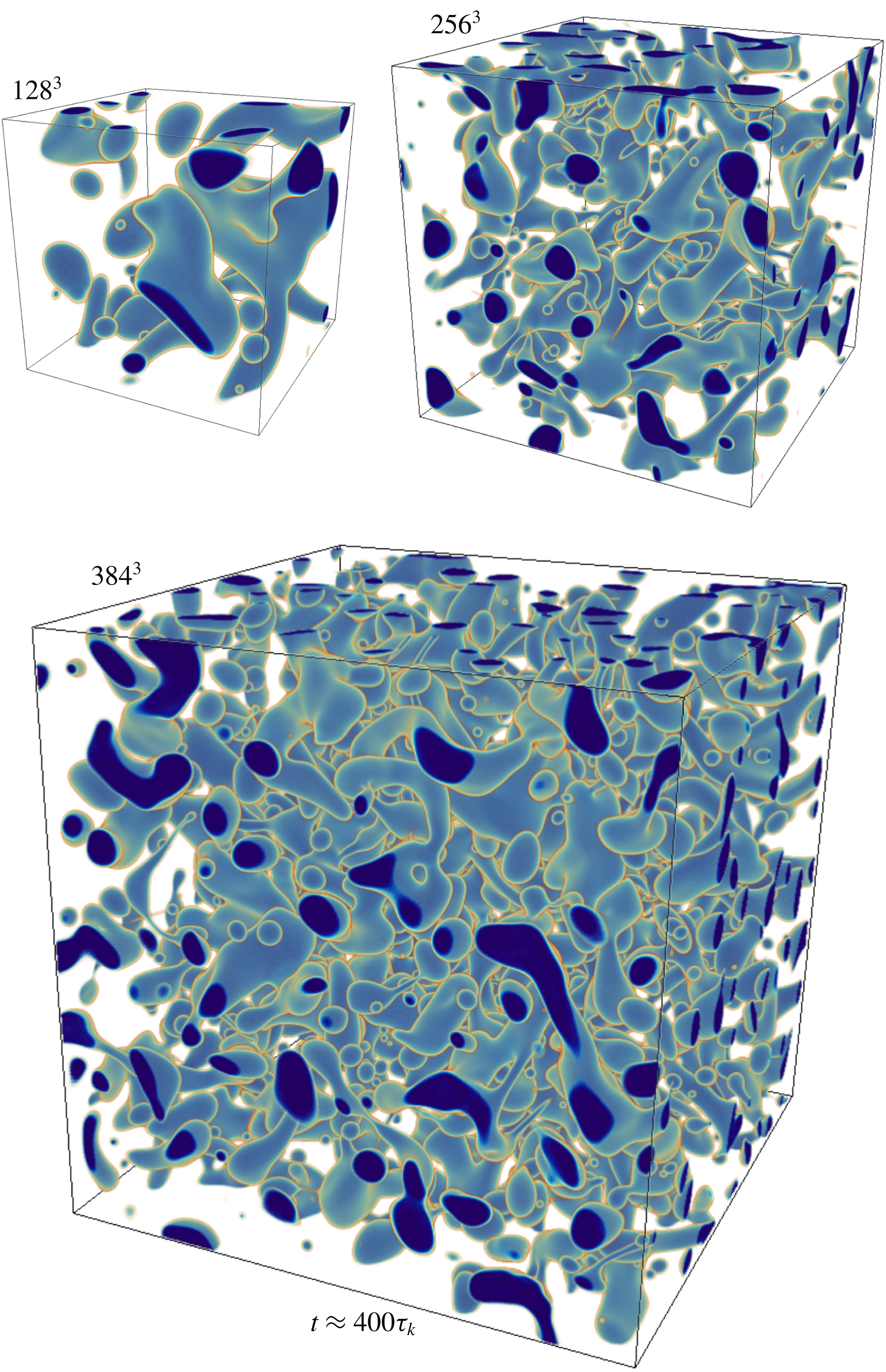
Figure 17. Volumetric droplet distribution for increasing domain sizes while maintaining the same energy density (power input) for cases D1, D2 and D3 with
 $N_{x}=128^{3},256^{3}$
and
$N_{x}=128^{3},256^{3}$
and
 $384^{3}$
respectively. The resolution of large droplet extensions becomes feasible at higher domain sizes. Here dark blue to orange goes from the droplet interior to the matrix phase.
$384^{3}$
respectively. The resolution of large droplet extensions becomes feasible at higher domain sizes. Here dark blue to orange goes from the droplet interior to the matrix phase.
The domain size limitation becomes apparent when considering the droplet distribution, as shown in figure 18. For the case of
 $N_{x}=128^{3}$
(D1), the distribution is limited to a small region around the peak, clearly being cut off at a secondary peak emerging at higher
$N_{x}=128^{3}$
(D1), the distribution is limited to a small region around the peak, clearly being cut off at a secondary peak emerging at higher
 $d/\unicode[STIX]{x1D702}$
due to a lack of resolution of larger structures. This case is under-resolved, the issue made acute with the small domain size, significant
$d/\unicode[STIX]{x1D702}$
due to a lack of resolution of larger structures. This case is under-resolved, the issue made acute with the small domain size, significant
 $\unicode[STIX]{x1D719}$
and moderate
$\unicode[STIX]{x1D719}$
and moderate
 $Re_{\unicode[STIX]{x1D706}}\approx 30$
. We include this case to emphasize that the same issue might arise in simulations with higher
$Re_{\unicode[STIX]{x1D706}}\approx 30$
. We include this case to emphasize that the same issue might arise in simulations with higher
 $Re_{\unicode[STIX]{x1D706}}$
and
$Re_{\unicode[STIX]{x1D706}}$
and
 $N_{x}$
of high volume fraction dispersions. Upon increasing
$N_{x}$
of high volume fraction dispersions. Upon increasing
 $N_{x}$
, the distribution successively assumes a longer tail which closely follows the
$N_{x}$
, the distribution successively assumes a longer tail which closely follows the
 $d^{-10/3}$
scaling for droplets larger than the Hinze scale.
$d^{-10/3}$
scaling for droplets larger than the Hinze scale.
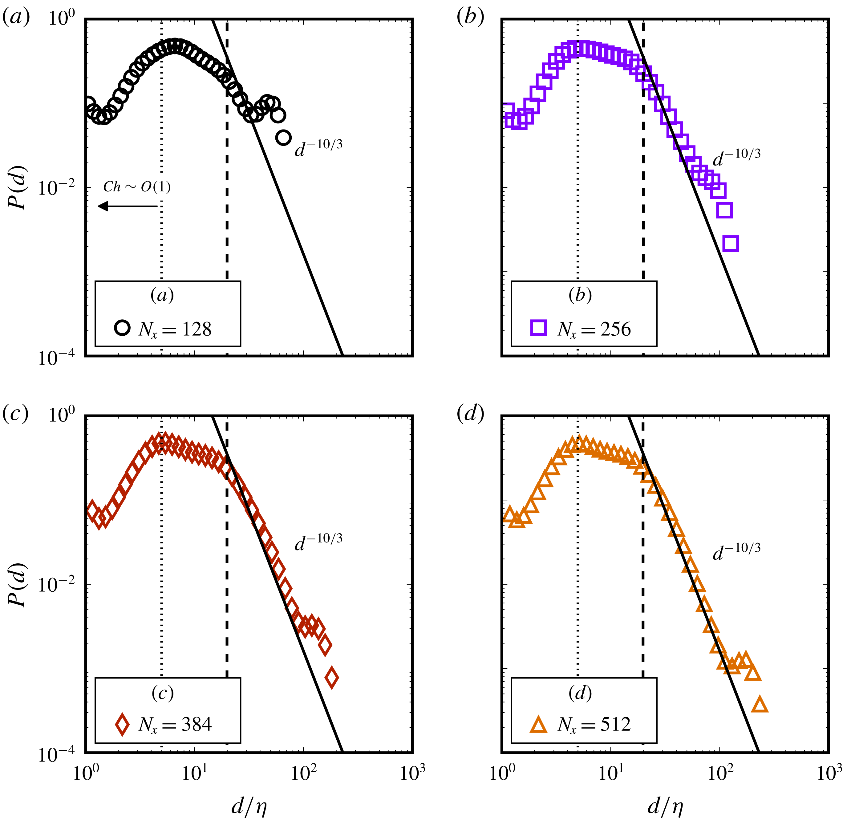
Figure 18. Droplet size distributions for cases D1–D4, all with
 $\unicode[STIX]{x1D719}=0.15$
and
$\unicode[STIX]{x1D719}=0.15$
and
 $Re_{\unicode[STIX]{x1D706}}\approx 30$
. The total number of droplets considered between times
$Re_{\unicode[STIX]{x1D706}}\approx 30$
. The total number of droplets considered between times
 $150\unicode[STIX]{x1D70F}_{k}{-}600\unicode[STIX]{x1D70F}_{k}$
are
$150\unicode[STIX]{x1D70F}_{k}{-}600\unicode[STIX]{x1D70F}_{k}$
are
 ${\approx}5000,40\,000,54\,000,133\,000$
for
${\approx}5000,40\,000,54\,000,133\,000$
for
 $N_{x}=128,256,384,512$
respectively. The dashed vertical line shows the Hinze scale and the dotted vertical line marks the limit
$N_{x}=128,256,384,512$
respectively. The dashed vertical line shows the Hinze scale and the dotted vertical line marks the limit
 $Ch\sim O(1)$
.
$Ch\sim O(1)$
.
Figure 19(a) shows the concentration spectrum for cases D1–D4, which first reflects the proper scaling as the spectra coincide for
 $k/k_{f}\geqslant 1$
. The importance of resolving the dominant lengthscales characterizing the dispersion morphology vis-à-vis the domain size
$k/k_{f}\geqslant 1$
. The importance of resolving the dominant lengthscales characterizing the dispersion morphology vis-à-vis the domain size
 $N_{x}$
becomes apparent. The smallest wavenumber (largest lengthscale) that can be represented depends on
$N_{x}$
becomes apparent. The smallest wavenumber (largest lengthscale) that can be represented depends on
 $N_{x}$
as
$N_{x}$
as
 $k_{min}=2\unicode[STIX]{x03C0}/N_{x}$
. For case D1,
$k_{min}=2\unicode[STIX]{x03C0}/N_{x}$
. For case D1,
 $k_{min}$
is very close to the wavenumber corresponding to the peak in the concentration spectrum, i.e. the dominant wavenumber
$k_{min}$
is very close to the wavenumber corresponding to the peak in the concentration spectrum, i.e. the dominant wavenumber
 $k_{d}$
(or lengthscale
$k_{d}$
(or lengthscale
 $N_{x}/k_{d}$
). If
$N_{x}/k_{d}$
). If
 $k_{min}\approx k_{d}$
, two issues would tend to arise. First, the dominant lengthscale of the emulsion morphology is comparable to the domain size making its dynamics under-resolved. Secondly, this structure will strongly interact with an image of itself due to periodicity of the domain, which is undesirable. For successively larger domains, the dominant lengthscale does not change (due to the same energy density across simulations). Further, the separation of
$k_{min}\approx k_{d}$
, two issues would tend to arise. First, the dominant lengthscale of the emulsion morphology is comparable to the domain size making its dynamics under-resolved. Secondly, this structure will strongly interact with an image of itself due to periodicity of the domain, which is undesirable. For successively larger domains, the dominant lengthscale does not change (due to the same energy density across simulations). Further, the separation of
 $k_{min}$
and
$k_{min}$
and
 $k_{d}$
is increased, which confirms that the largest structures (
$k_{d}$
is increased, which confirms that the largest structures (
 ${\sim}N_{x}/k_{d}$
) are well resolved, while even larger structures (in the range of
${\sim}N_{x}/k_{d}$
) are well resolved, while even larger structures (in the range of
 $k<k_{d}$
) are formed but not sustained as the peak of
$k<k_{d}$
) are formed but not sustained as the peak of
 $S(k)$
resides at
$S(k)$
resides at
 $k_{d}$
. The characteristic length evolution in figure 19(b) also shows that the morphology obtained for D1–D4 is similar, and that the typical lengthscale
$k_{d}$
. The characteristic length evolution in figure 19(b) also shows that the morphology obtained for D1–D4 is similar, and that the typical lengthscale
 $L(t)\approx 80$
becomes better resolved in relation to the grid size upon increasing
$L(t)\approx 80$
becomes better resolved in relation to the grid size upon increasing
 $N_{x}$
.
$N_{x}$
.
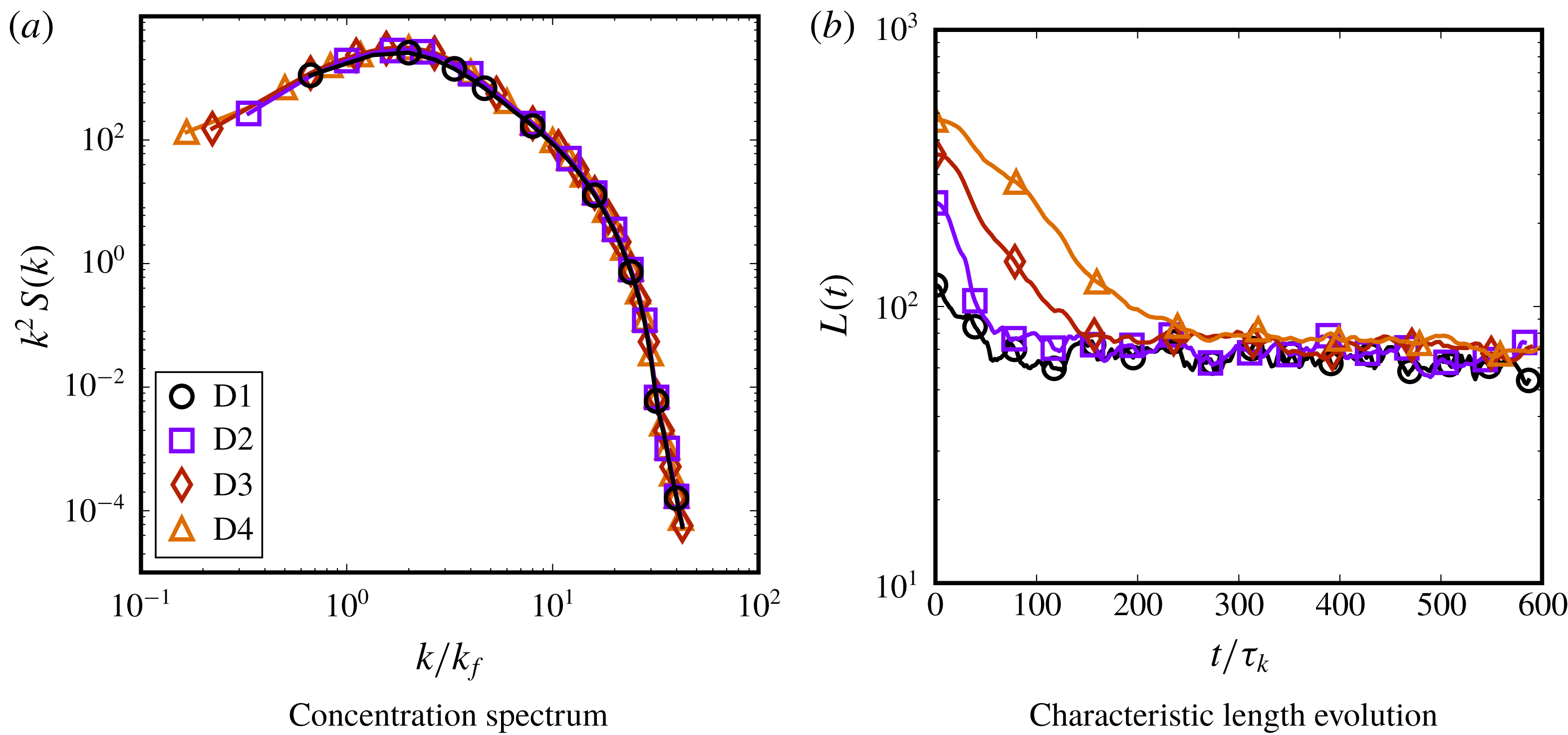
Figure 19. Dispersion morphology characterized with the (a) concentration spectrum
 $k^{2}S(k,t)$
and (b) characteristic length
$k^{2}S(k,t)$
and (b) characteristic length
 $L(t)$
for cases D1–D4. The concentration spectrum is averaged between times
$L(t)$
for cases D1–D4. The concentration spectrum is averaged between times
 $150\unicode[STIX]{x1D70F}_{k}{-}600\unicode[STIX]{x1D70F}_{k}$
, sampled every
$150\unicode[STIX]{x1D70F}_{k}{-}600\unicode[STIX]{x1D70F}_{k}$
, sampled every
 $4\unicode[STIX]{x1D70F}_{k}$
. The importance of separation between the domain size
$4\unicode[STIX]{x1D70F}_{k}$
. The importance of separation between the domain size
 $N_{x}$
or
$N_{x}$
or
 $k_{min}$
and the dominant lengthscales characterizing the dispersion, i.e.
$k_{min}$
and the dominant lengthscales characterizing the dispersion, i.e.
 $k_{d}$
or
$k_{d}$
or
 $L(t)$
, is evident from the fact that these two lengthscales can become comparable.
$L(t)$
, is evident from the fact that these two lengthscales can become comparable.
4.13 Effect of forcing wavenumber
To highlight the consequences of forcing turbulence at the largest possible scale, i.e. having
 ${\mathcal{L}}$
comparable to
${\mathcal{L}}$
comparable to
 $N_{x}$
(hence maximizing
$N_{x}$
(hence maximizing
 $Re_{\unicode[STIX]{x1D706}}$
), we performed an additional simulation D5 with
$Re_{\unicode[STIX]{x1D706}}$
), we performed an additional simulation D5 with
 $k_{f}=1.5k_{min}$
and
$k_{f}=1.5k_{min}$
and
 $\unicode[STIX]{x1D719}=0.2$
to compare with D4 (
$\unicode[STIX]{x1D719}=0.2$
to compare with D4 (
 $k_{f}=6k_{min}$
,
$k_{f}=6k_{min}$
,
 $\unicode[STIX]{x1D719}=0.15$
), while keeping the forcing amplitude the same, which results in
$\unicode[STIX]{x1D719}=0.15$
), while keeping the forcing amplitude the same, which results in
 $Re_{\unicode[STIX]{x1D706}}=118$
for case D5 (while
$Re_{\unicode[STIX]{x1D706}}=118$
for case D5 (while
 $Re_{\unicode[STIX]{x1D706}}=30$
for D4). Figure 20 shows the typical morphology of the droplets (at a random time instance), where visibly the D4 case seems to have smaller, more spherical droplets, while D5 shows more elongated filaments. Despite the higher
$Re_{\unicode[STIX]{x1D706}}=30$
for D4). Figure 20 shows the typical morphology of the droplets (at a random time instance), where visibly the D4 case seems to have smaller, more spherical droplets, while D5 shows more elongated filaments. Despite the higher
 $Re_{\unicode[STIX]{x1D706}}$
, the dispersion does not comprise smaller droplets as droplet sizes depend on
$Re_{\unicode[STIX]{x1D706}}$
, the dispersion does not comprise smaller droplets as droplet sizes depend on
 $\langle \unicode[STIX]{x1D716}\rangle$
which remains mostly unchanged. The presence of elongated filaments in D5 reflects the nature of the turbulence forcing. For a long cylindrical filament, a higher wavenumber forcing will generate more curvature variations. This would increase the possibility of filament breakup driven by Rayleigh–Plateau instabilities. A lower wavenumber forcing would generate weaker curvature differences in a long filament, and the timescale of breakup of these filaments might be comparable to the timescale of the large eddies, in which case the filaments will only break when the direction of the large-scale shear changes.
$\langle \unicode[STIX]{x1D716}\rangle$
which remains mostly unchanged. The presence of elongated filaments in D5 reflects the nature of the turbulence forcing. For a long cylindrical filament, a higher wavenumber forcing will generate more curvature variations. This would increase the possibility of filament breakup driven by Rayleigh–Plateau instabilities. A lower wavenumber forcing would generate weaker curvature differences in a long filament, and the timescale of breakup of these filaments might be comparable to the timescale of the large eddies, in which case the filaments will only break when the direction of the large-scale shear changes.
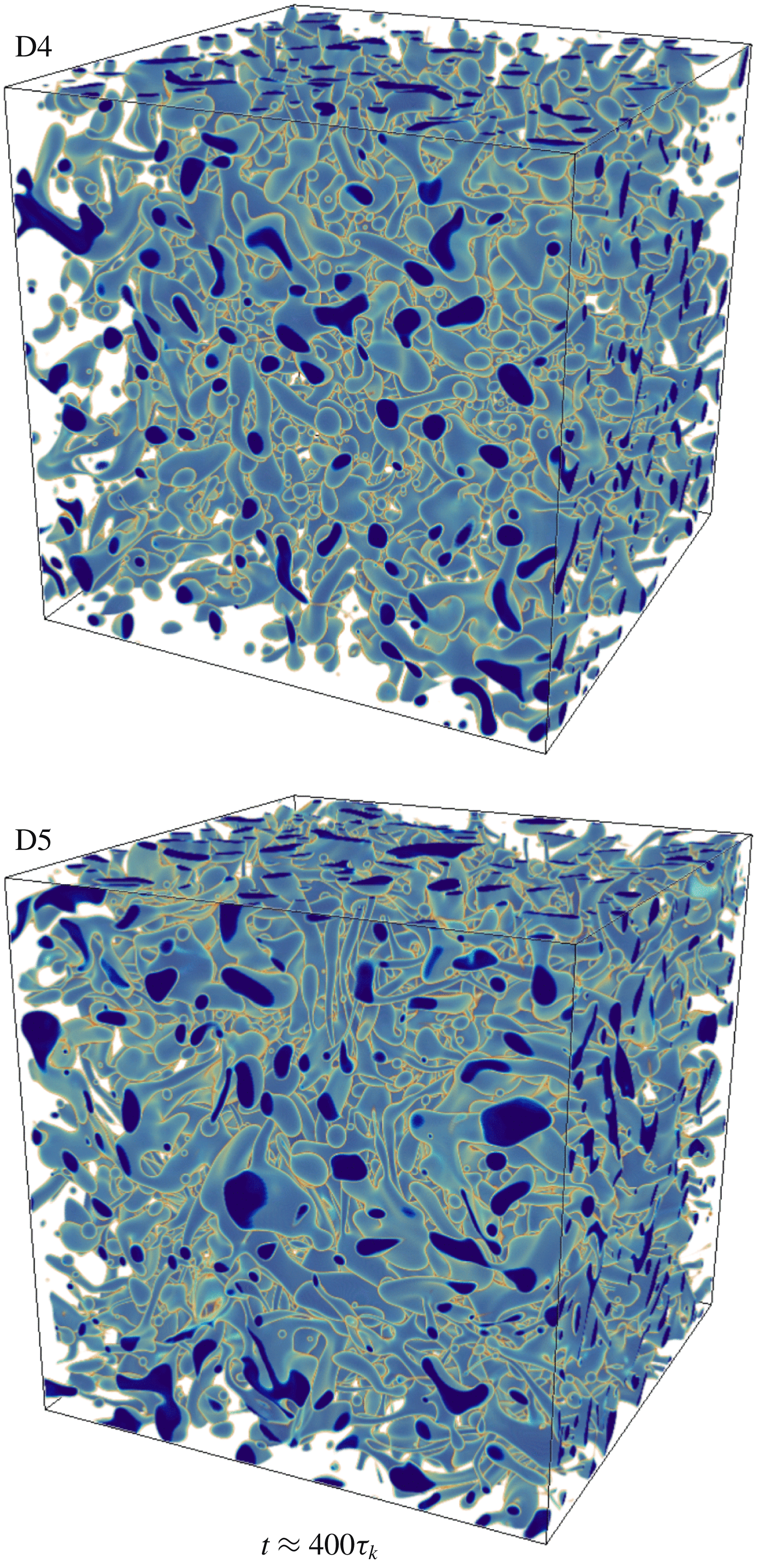
Figure 20. Volumetric droplet distribution for cases D4 and D5, where the forcing wavenumber is changed from
 $k_{f}=6$
to
$k_{f}=6$
to
 $k_{f}=1.5$
, shown at
$k_{f}=1.5$
, shown at
 $400\unicode[STIX]{x1D70F}_{k}$
. The D4 case shows a preponderance of smaller, more spherical droplets while D5 has more elongated filaments, possibly sustained due to the long wavelength of the forcing.
$400\unicode[STIX]{x1D70F}_{k}$
. The D4 case shows a preponderance of smaller, more spherical droplets while D5 has more elongated filaments, possibly sustained due to the long wavelength of the forcing.
We further quantify the differences by calculating the droplet distribution for D4 and D5 (which have slightly different
 $\unicode[STIX]{x1D719}$
), while also comparing simulations D2 (with
$\unicode[STIX]{x1D719}$
), while also comparing simulations D2 (with
 $k_{f}=3.0$
and
$k_{f}=3.0$
and
 $Re_{\unicode[STIX]{x1D706}}=30$
) and P3 (
$Re_{\unicode[STIX]{x1D706}}=30$
) and P3 (
 $k_{f}=2.0$
and
$k_{f}=2.0$
and
 $Re_{\unicode[STIX]{x1D706}}=47$
) which have the same
$Re_{\unicode[STIX]{x1D706}}=47$
) which have the same
 $\unicode[STIX]{x1D719}$
, shown in figure 21. Indeed, the D5 case deviates from the
$\unicode[STIX]{x1D719}$
, shown in figure 21. Indeed, the D5 case deviates from the
 $d^{-10/3}$
distribution above the Hinze scale, reflecting the infrequent breakup of the long filaments that would lead to droplets in this range of sizes. This deficit of droplets shows up in a secondary peak at high
$d^{-10/3}$
distribution above the Hinze scale, reflecting the infrequent breakup of the long filaments that would lead to droplets in this range of sizes. This deficit of droplets shows up in a secondary peak at high
 $d/\unicode[STIX]{x1D702}$
, which corresponds to the fewer, larger structures being sustained instead. A similar difference is seen between cases D2 and P3, where the P3 case shows a small peak at high
$d/\unicode[STIX]{x1D702}$
, which corresponds to the fewer, larger structures being sustained instead. A similar difference is seen between cases D2 and P3, where the P3 case shows a small peak at high
 $d/\unicode[STIX]{x1D702}$
, again attributed to a lower wavenumber forcing. The same behaviour is reflected in the concentration spectrum as well between the cases (not shown here) where there is a relative increase in concentration at low wavenumbers for cases D5 and P3, although the characteristic length remains similar.
$d/\unicode[STIX]{x1D702}$
, again attributed to a lower wavenumber forcing. The same behaviour is reflected in the concentration spectrum as well between the cases (not shown here) where there is a relative increase in concentration at low wavenumbers for cases D5 and P3, although the characteristic length remains similar.
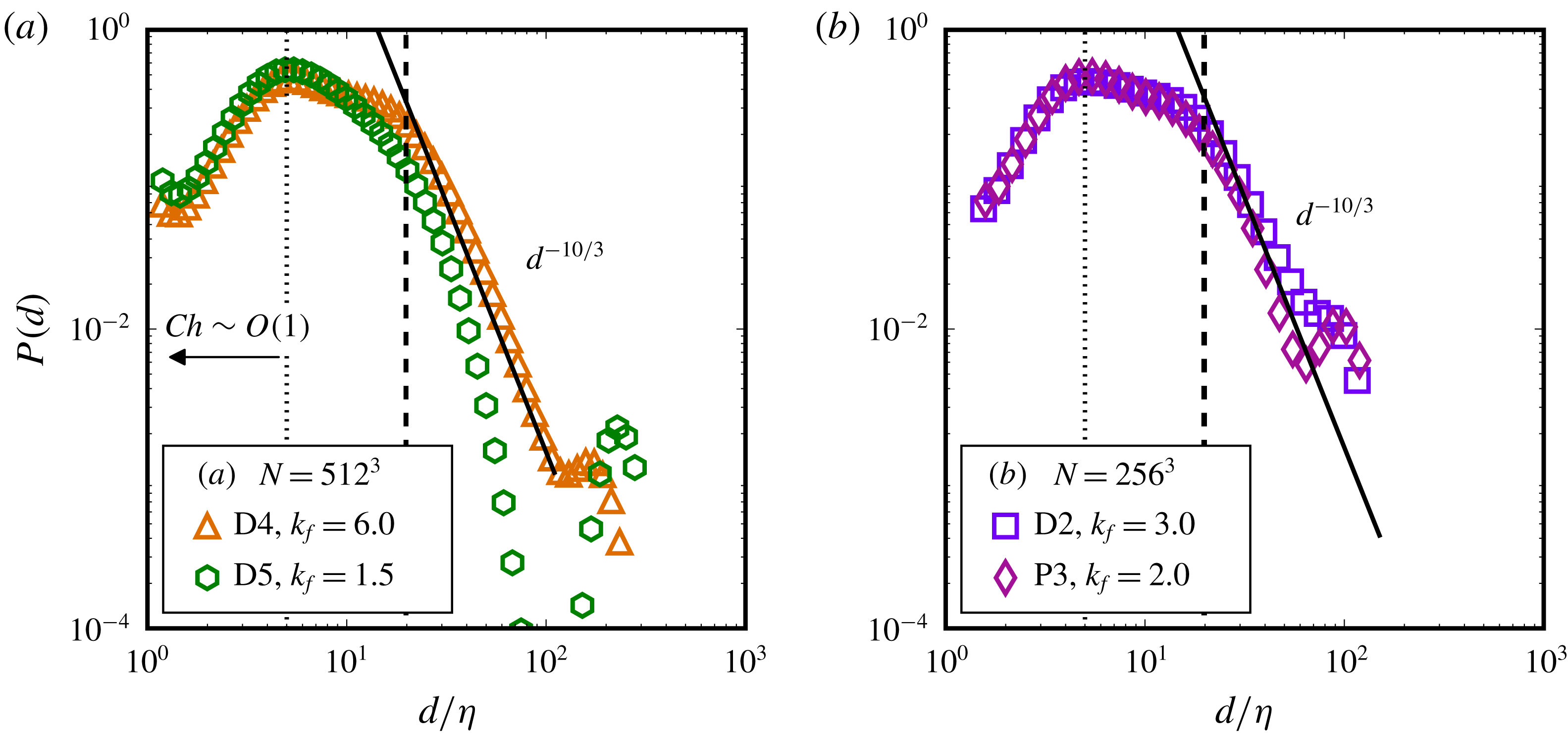
Figure 21. Droplet size distributions comparing (a) cases D4 (
 $k_{f}=6.0$
,
$k_{f}=6.0$
,
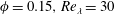 $\unicode[STIX]{x1D719}=0.15,Re_{\unicode[STIX]{x1D706}}=30$
) and D5 (
$\unicode[STIX]{x1D719}=0.15,Re_{\unicode[STIX]{x1D706}}=30$
) and D5 (
 $k_{f}=1.5,\unicode[STIX]{x1D719}=0.20,Re_{\unicode[STIX]{x1D706}}=118$
), and (b) cases D2 (
$k_{f}=1.5,\unicode[STIX]{x1D719}=0.20,Re_{\unicode[STIX]{x1D706}}=118$
), and (b) cases D2 (
 $k_{f}=3.0,Re_{\unicode[STIX]{x1D706}}=30$
) and P3 (
$k_{f}=3.0,Re_{\unicode[STIX]{x1D706}}=30$
) and P3 (
 $k_{f}=2.0,Re_{\unicode[STIX]{x1D706}}=47$
).
$k_{f}=2.0,Re_{\unicode[STIX]{x1D706}}=47$
).
Figure 22. Evolution of state-space variables
 $N_{d}$
,
$N_{d}$
,
 $\langle E_{k}\rangle$
,
$\langle E_{k}\rangle$
,
 $\langle \unicode[STIX]{x1D714}^{2}\rangle$
and
$\langle \unicode[STIX]{x1D714}^{2}\rangle$
and
 $\langle E_{\unicode[STIX]{x1D6FE}}\rangle$
(from case T5). The
$\langle E_{\unicode[STIX]{x1D6FE}}\rangle$
(from case T5). The
 $y$
-axis is in arbitrary units [a.u.] for each quantity since they have been normalized by their time-averaged values between
$y$
-axis is in arbitrary units [a.u.] for each quantity since they have been normalized by their time-averaged values between
 $50\unicode[STIX]{x1D70F}_{k}$
and
$50\unicode[STIX]{x1D70F}_{k}$
and
 $1000\unicode[STIX]{x1D70F}_{k}$
, to scale the fluctuations to around a mean value of
$1000\unicode[STIX]{x1D70F}_{k}$
, to scale the fluctuations to around a mean value of
 $1$
(to facilitate visual comparison between the different curves). In panels (a) to (c), peaks in
$1$
(to facilitate visual comparison between the different curves). In panels (a) to (c), peaks in
 $\langle E_{k}\rangle$
are shown to be manifested in the
$\langle E_{k}\rangle$
are shown to be manifested in the
 $\langle \unicode[STIX]{x1D714}^{2}\rangle$
evolution with a small time delay, which are then found in the
$\langle \unicode[STIX]{x1D714}^{2}\rangle$
evolution with a small time delay, which are then found in the
 $N_{d}$
evolution with a further time delay, in a cascade of cause and effect. Two such instances have been shown using the vertical lines extending from panel (a) to panel (c), which approximately indicate individual sequences of cascading events. Similarly, peaks in
$N_{d}$
evolution with a further time delay, in a cascade of cause and effect. Two such instances have been shown using the vertical lines extending from panel (a) to panel (c), which approximately indicate individual sequences of cascading events. Similarly, peaks in
 $\langle E_{\unicode[STIX]{x1D6FE}}\rangle$
are found to precede peaks in
$\langle E_{\unicode[STIX]{x1D6FE}}\rangle$
are found to precede peaks in
 $N_{d}$
, two instances of which have also been shown using the vertical lines between panels (c) and (d).
$N_{d}$
, two instances of which have also been shown using the vertical lines between panels (c) and (d).
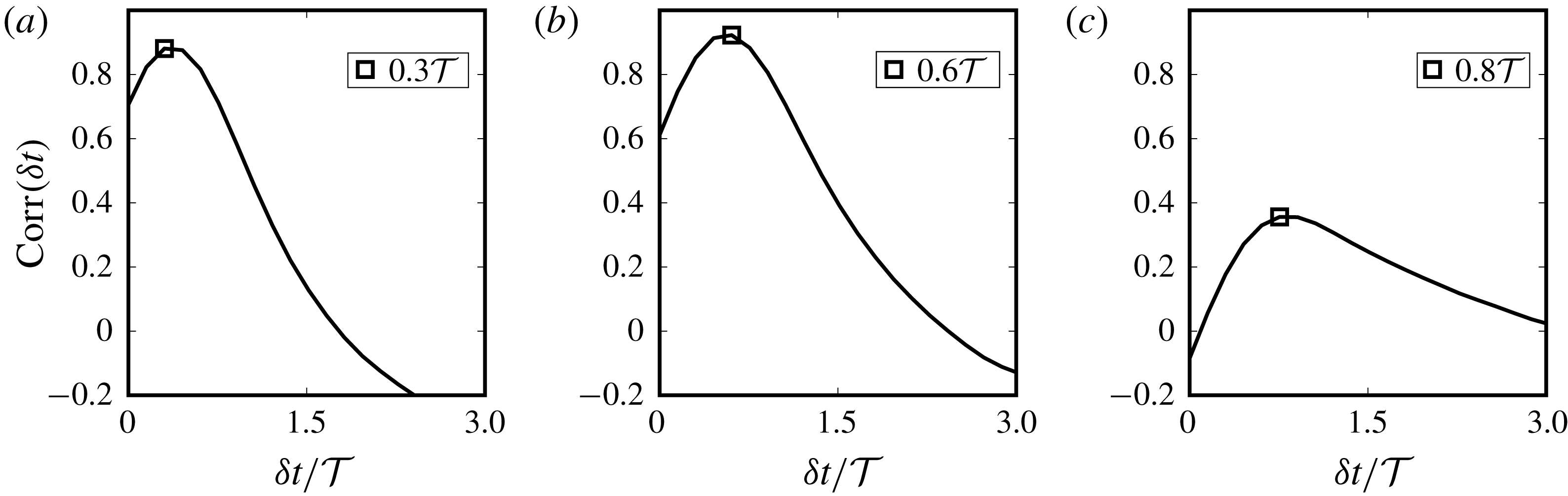
Figure 23. Correlation between
 $N_{d}$
,
$N_{d}$
,
 $\langle E_{k}\rangle$
and
$\langle E_{k}\rangle$
and
 $\langle \unicode[STIX]{x1D714}^{2}\rangle$
for case T5. Here
$\langle \unicode[STIX]{x1D714}^{2}\rangle$
for case T5. Here
 $N_{d}$
consistently correlates strongly with
$N_{d}$
consistently correlates strongly with
 $\langle E_{k}\rangle$
with a temporal delay of
$\langle E_{k}\rangle$
with a temporal delay of
 $0.9{\mathcal{T}}$
, while
$0.9{\mathcal{T}}$
, while
 $\langle E_{\unicode[STIX]{x1D6FE}}\rangle$
is found to attain its maximum value before
$\langle E_{\unicode[STIX]{x1D6FE}}\rangle$
is found to attain its maximum value before
 $N_{d}$
, hinting that breakup occurs via extension of droplets into long filaments.
$N_{d}$
, hinting that breakup occurs via extension of droplets into long filaments.
It is worthwhile to summarize the results from the domain size comparison and to draw conclusions. At modest
 $Re_{\unicode[STIX]{x1D706}}$
(
$Re_{\unicode[STIX]{x1D706}}$
(
 ${<}120$
in this study), the turbulence forcing wavelength and domain size influence the morphology. Having
${<}120$
in this study), the turbulence forcing wavelength and domain size influence the morphology. Having
 $N_{x}>{\mathcal{L}}\gg d$
(as in case D4) ensures sufficient resolution of the droplet breakup dynamics, while having
$N_{x}>{\mathcal{L}}\gg d$
(as in case D4) ensures sufficient resolution of the droplet breakup dynamics, while having
 $N_{x}\approx {\mathcal{L}}\gg d$
(case D5) causes the formation of longer filaments of the droplet fluid. Spatially, this causes the formation of larger droplets
$N_{x}\approx {\mathcal{L}}\gg d$
(case D5) causes the formation of longer filaments of the droplet fluid. Spatially, this causes the formation of larger droplets
 $d/\unicode[STIX]{x1D702}>100$
at the cost of some intermediate droplets
$d/\unicode[STIX]{x1D702}>100$
at the cost of some intermediate droplets
 $20<d/\unicode[STIX]{x1D702}<100$
, for
$20<d/\unicode[STIX]{x1D702}<100$
, for
 $d/\unicode[STIX]{x1D702}$
above the Hinze scale.
$d/\unicode[STIX]{x1D702}$
above the Hinze scale.
5 Turbulent emulsion dynamics
5.1 A quasi-equilibrium (limit) cycle
Droplet number density plots such as figure 15 show oscillations of
 $N_{d}$
around a typical mean value which characterizes the dispersion morphology. So far, studies on droplets in turbulence refer to this state as a ‘steady state’ where coalescence and breakup equilibrate. Since these oscillations can be significant (with their extreme values remaining bounded, similar to kinetic energy and dissipation), the dynamics should more accurately be called a quasi-equilibrium (limit) cycle in the system state-space comprising (i) kinetic energy
$N_{d}$
around a typical mean value which characterizes the dispersion morphology. So far, studies on droplets in turbulence refer to this state as a ‘steady state’ where coalescence and breakup equilibrate. Since these oscillations can be significant (with their extreme values remaining bounded, similar to kinetic energy and dissipation), the dynamics should more accurately be called a quasi-equilibrium (limit) cycle in the system state-space comprising (i) kinetic energy
 $\langle E_{k}\rangle$
, (ii) enstrophy
$\langle E_{k}\rangle$
, (ii) enstrophy
 $\langle \unicode[STIX]{x1D714}^{2}\rangle$
, which is defined as
$\langle \unicode[STIX]{x1D714}^{2}\rangle$
, which is defined as
 $\langle \unicode[STIX]{x1D714}^{2}\rangle =\langle \unicode[STIX]{x1D74E}\boldsymbol{\cdot }\unicode[STIX]{x1D74E}\rangle$
(where
$\langle \unicode[STIX]{x1D714}^{2}\rangle =\langle \unicode[STIX]{x1D74E}\boldsymbol{\cdot }\unicode[STIX]{x1D74E}\rangle$
(where
 $\unicode[STIX]{x1D74E}=\unicode[STIX]{x1D735}\times \boldsymbol{u}$
is the vorticity), (iii) interfacial energy
$\unicode[STIX]{x1D74E}=\unicode[STIX]{x1D735}\times \boldsymbol{u}$
is the vorticity), (iii) interfacial energy
 $\langle E_{\unicode[STIX]{x1D6FE}}\rangle =\langle S_{A}\unicode[STIX]{x1D6FE}\rangle$
(i.e. the product of the total interfacial area
$\langle E_{\unicode[STIX]{x1D6FE}}\rangle =\langle S_{A}\unicode[STIX]{x1D6FE}\rangle$
(i.e. the product of the total interfacial area
 $S_{A}$
and the interfacial tension
$S_{A}$
and the interfacial tension
 $\unicode[STIX]{x1D6FE}$
) and (iv) the droplet number density
$\unicode[STIX]{x1D6FE}$
) and (iv) the droplet number density
 $N_{d}$
. Here
$N_{d}$
. Here
 $\langle .\rangle$
denotes volume averaging of the quantities. Coalescence and breakup equilibrate in a statistical sense only, while the instantaneous dynamics is governed by temporal branches of alternating dominance of coalescence and breakup. Note that the term ‘limit cycle’ is used loosely to illustrate the dynamics, since truly closed trajectories in phase space were not found, perhaps primarily due to intermittency and non-periodicity of the numerical solutions.
$\langle .\rangle$
denotes volume averaging of the quantities. Coalescence and breakup equilibrate in a statistical sense only, while the instantaneous dynamics is governed by temporal branches of alternating dominance of coalescence and breakup. Note that the term ‘limit cycle’ is used loosely to illustrate the dynamics, since truly closed trajectories in phase space were not found, perhaps primarily due to intermittency and non-periodicity of the numerical solutions.
A dominant mediator of droplet breakup is the rate of kinetic energy dissipation
 $\langle \unicode[STIX]{x1D716}\rangle$
(or
$\langle \unicode[STIX]{x1D716}\rangle$
(or
 $\langle \unicode[STIX]{x1D714}^{2}\rangle$
). Since dissipation destroys turbulent kinetic energy, it is interesting to note that its interaction with the dispersed phase is associated with interfacial wrinkling, deformation and breakup – all mechanisms that increase the amount of surface energy in the system at the cost of kinetic energy. This excess energy, however, is still available in the flow field, and true destruction of it (i.e. into heat) must be mediated via kinetic energy dissipation, which occurs by the generation of smaller scales in the flow due to coalescence or damped oscillations of deformed droplet interfaces. A higher globally averaged
$\langle \unicode[STIX]{x1D714}^{2}\rangle$
). Since dissipation destroys turbulent kinetic energy, it is interesting to note that its interaction with the dispersed phase is associated with interfacial wrinkling, deformation and breakup – all mechanisms that increase the amount of surface energy in the system at the cost of kinetic energy. This excess energy, however, is still available in the flow field, and true destruction of it (i.e. into heat) must be mediated via kinetic energy dissipation, which occurs by the generation of smaller scales in the flow due to coalescence or damped oscillations of deformed droplet interfaces. A higher globally averaged
 $\langle \unicode[STIX]{x1D714}^{2}\rangle$
can be expected to increase the chance of droplet breakup (as it also reduces the effective Hinze scale), and vice-versa. Hence the trends seen in the
$\langle \unicode[STIX]{x1D714}^{2}\rangle$
can be expected to increase the chance of droplet breakup (as it also reduces the effective Hinze scale), and vice-versa. Hence the trends seen in the
 $N_{d}$
evolution should reflect those in the evolution of
$N_{d}$
evolution should reflect those in the evolution of
 $\langle \unicode[STIX]{x1D714}^{2}\rangle$
, which in turn should follow the peaks and valleys of the kinetic energy
$\langle \unicode[STIX]{x1D714}^{2}\rangle$
, which in turn should follow the peaks and valleys of the kinetic energy
 $\langle E_{k}\rangle$
evolution.
$\langle E_{k}\rangle$
evolution.
This hypothesis is found to be true, and is shown in figure 22 in the evolution of
 $\langle E_{k}\rangle$
,
$\langle E_{k}\rangle$
,
 $\langle \unicode[STIX]{x1D714}^{2}\rangle$
,
$\langle \unicode[STIX]{x1D714}^{2}\rangle$
,
 $N_{d}$
and
$N_{d}$
and
 $\langle E_{\unicode[STIX]{x1D6FE}}\rangle$
for case T5. Here each variable has been normalized by its time average (between
$\langle E_{\unicode[STIX]{x1D6FE}}\rangle$
for case T5. Here each variable has been normalized by its time average (between
 $50\unicode[STIX]{x1D70F}_{k}$
and
$50\unicode[STIX]{x1D70F}_{k}$
and
 $1000\unicode[STIX]{x1D70F}_{k}$
), such that it oscillates around a mean value of
$1000\unicode[STIX]{x1D70F}_{k}$
), such that it oscillates around a mean value of
 $1$
, which is done merely to facilitate comparison between the different curves. The peaks in
$1$
, which is done merely to facilitate comparison between the different curves. The peaks in
 $\langle E_{k}\rangle$
(a) are found to consistently be manifested in
$\langle E_{k}\rangle$
(a) are found to consistently be manifested in
 $\langle \unicode[STIX]{x1D714}^{2}\rangle$
(b) with a small time delay, which are again found with a further time delay in the evolution of
$\langle \unicode[STIX]{x1D714}^{2}\rangle$
(b) with a small time delay, which are again found with a further time delay in the evolution of
 $N_{d}$
(c). Two such instances have been marked by the three successive vertical lines than connect panels (a–c), coinciding approximately with the local peaks of the different curves. Similarly, peaks in the evolution of
$N_{d}$
(c). Two such instances have been marked by the three successive vertical lines than connect panels (a–c), coinciding approximately with the local peaks of the different curves. Similarly, peaks in the evolution of
 $\langle E_{\unicode[STIX]{x1D6FE}}\rangle$
(d) are found to precede peaks in
$\langle E_{\unicode[STIX]{x1D6FE}}\rangle$
(d) are found to precede peaks in
 $N_{d}$
(c), two instances of which have also been similarly marked by vertical lines spanning those two panels of figure 22. This shows clearly that the droplet surface area (since here
$N_{d}$
(c), two instances of which have also been similarly marked by vertical lines spanning those two panels of figure 22. This shows clearly that the droplet surface area (since here
 $E_{\unicode[STIX]{x1D6FE}}\propto S_{A}$
) is at its maximum before breakup, which hints that the droplet breakup mechanism is mainly the extension of filaments. Since droplet breakup leads to an increase in surface area – for example a spherical droplet breaking into
$E_{\unicode[STIX]{x1D6FE}}\propto S_{A}$
) is at its maximum before breakup, which hints that the droplet breakup mechanism is mainly the extension of filaments. Since droplet breakup leads to an increase in surface area – for example a spherical droplet breaking into
 $n$
equal-volume daughter droplets leads to an increase in surface area by a factor of
$n$
equal-volume daughter droplets leads to an increase in surface area by a factor of
 $n^{1/3}$
– the peak in surface area prior to breakup signifies that the droplet before breakup must be significantly elongated to have a larger surface area than the subsequently formed daughter droplets. This also shows that a single droplet does not break into many daughter droplets at once, and the process is cascading, since otherwise a large number of daughter droplets will lead to higher surface areas after breakup, not before it. A correlation between the evolution of different variables can be calculated as
$n^{1/3}$
– the peak in surface area prior to breakup signifies that the droplet before breakup must be significantly elongated to have a larger surface area than the subsequently formed daughter droplets. This also shows that a single droplet does not break into many daughter droplets at once, and the process is cascading, since otherwise a large number of daughter droplets will lead to higher surface areas after breakup, not before it. A correlation between the evolution of different variables can be calculated as
 $$\begin{eqnarray}\text{Corr}(\unicode[STIX]{x1D6FF}t)=\frac{\overline{\langle E_{k}(t)\rangle \langle \unicode[STIX]{x1D714}^{2}(t+\unicode[STIX]{x1D6FF}t)\rangle }}{\overline{\langle E_{k}\rangle }~\overline{\langle \unicode[STIX]{x1D714}^{2}\rangle }},\end{eqnarray}$$
where
 $\unicode[STIX]{x1D6FF}t$
is a time lag and the overbar is a temporal average. This has been done for the different signal pairs and is shown in figure 23. Here
$\unicode[STIX]{x1D6FF}t$
is a time lag and the overbar is a temporal average. This has been done for the different signal pairs and is shown in figure 23. Here
 $\langle \unicode[STIX]{x1D714}^{2}\rangle$
is found to correlate strongly with
$\langle \unicode[STIX]{x1D714}^{2}\rangle$
is found to correlate strongly with
 $\langle E_{k}\rangle$
with a time delay of
$\langle E_{k}\rangle$
with a time delay of
 ${\sim}0.3{\mathcal{T}}$
while
${\sim}0.3{\mathcal{T}}$
while
 $N_{d}$
shows a very strong correlation with
$N_{d}$
shows a very strong correlation with
 $\langle \unicode[STIX]{x1D714}^{2}\rangle$
at a time delay of
$\langle \unicode[STIX]{x1D714}^{2}\rangle$
at a time delay of
 ${\sim}0.6{\mathcal{T}}$
. Consequently, a significant correlation between
${\sim}0.6{\mathcal{T}}$
. Consequently, a significant correlation between
 $N_{d}$
and
$N_{d}$
and
 $\langle E_{k}\rangle$
is found at
$\langle E_{k}\rangle$
is found at
 ${\sim}0.9{\mathcal{T}}$
. The converse effect of droplets on turbulence is also hinted at in this figure, where the valleys of the
${\sim}0.9{\mathcal{T}}$
. The converse effect of droplets on turbulence is also hinted at in this figure, where the valleys of the
 $N_{d}$
evolution often coincide with peaks in the
$N_{d}$
evolution often coincide with peaks in the
 $\langle E_{k}\rangle$
evolution. This shows that when the droplet number density reduces due to coalescence, the excess surface energy is released into the flow as kinetic energy, which has been expounded by Dodd & Ferrante (Reference Dodd and Ferrante2016). Since turbulence in our simulations is constantly forced (as opposed to Dodd & Ferrante (Reference Dodd and Ferrante2016) who simulate droplets in decaying turbulence) the variation in
$\langle E_{k}\rangle$
evolution. This shows that when the droplet number density reduces due to coalescence, the excess surface energy is released into the flow as kinetic energy, which has been expounded by Dodd & Ferrante (Reference Dodd and Ferrante2016). Since turbulence in our simulations is constantly forced (as opposed to Dodd & Ferrante (Reference Dodd and Ferrante2016) who simulate droplets in decaying turbulence) the variation in
 $\langle E_{k}\rangle$
in our simulations comes from a more complex confluence of the power input as well as the droplet dynamics. The correlation of surface energy
$\langle E_{k}\rangle$
in our simulations comes from a more complex confluence of the power input as well as the droplet dynamics. The correlation of surface energy
 $\langle E_{\unicode[STIX]{x1D6FE}}\rangle$
and
$\langle E_{\unicode[STIX]{x1D6FE}}\rangle$
and
 $N_{d}$
is shown in figure 23(c), where a weaker but certain correlation between
$N_{d}$
is shown in figure 23(c), where a weaker but certain correlation between
 $\langle E_{\unicode[STIX]{x1D6FE}}\rangle$
and
$\langle E_{\unicode[STIX]{x1D6FE}}\rangle$
and
 $N_{d}$
is found with a time lag of
$N_{d}$
is found with a time lag of
 $0.8{\mathcal{T}}$
.
$0.8{\mathcal{T}}$
.
We also observed this time-delayed dynamics of
 $\langle E_{k}\rangle$
and
$\langle E_{k}\rangle$
and
 $N_{d}$
for cases with different parameters such as turbulence forcing amplitude and interfacial tension, although for some cases the effect was less explicit. Particularly, for weaker
$N_{d}$
for cases with different parameters such as turbulence forcing amplitude and interfacial tension, although for some cases the effect was less explicit. Particularly, for weaker
 $\unicode[STIX]{x1D6FE}$
or lower
$\unicode[STIX]{x1D6FE}$
or lower
 $Re_{\unicode[STIX]{x1D706}}$
, the
$Re_{\unicode[STIX]{x1D706}}$
, the
 $N_{d}$
oscillations were not as extreme as for case T5 (where turbulence intensity and interfacial tension are both relatively stronger forces), although the
$N_{d}$
oscillations were not as extreme as for case T5 (where turbulence intensity and interfacial tension are both relatively stronger forces), although the
 $\langle E_{k}\rangle$
and
$\langle E_{k}\rangle$
and
 $N_{d}$
correlation was found to be strong. Generally, the dynamics can be described as follows. First, the large-scale structures generate higher velocity gradients at the dissipation scale (which may be due to the energy cascade if such exists) with an initial time lag. This larger dissipation rate is felt by the droplets, which respond by breaking up with a further time delay, increasing the number of droplets in the system. This process (from peaks in
$N_{d}$
correlation was found to be strong. Generally, the dynamics can be described as follows. First, the large-scale structures generate higher velocity gradients at the dissipation scale (which may be due to the energy cascade if such exists) with an initial time lag. This larger dissipation rate is felt by the droplets, which respond by breaking up with a further time delay, increasing the number of droplets in the system. This process (from peaks in
 $\langle E_{k}\rangle$
to peaks in
$\langle E_{k}\rangle$
to peaks in
 $N_{d}$
) was consistently found to take place with a delay of around
$N_{d}$
) was consistently found to take place with a delay of around
 ${\sim}0.9{\mathcal{T}}$
across different cases, which is roughly the lifetime of the large eddies. This finding can be important for droplet dynamics models such as population balance equations, where breakup kernels rely upon the instantaneous local value of
${\sim}0.9{\mathcal{T}}$
across different cases, which is roughly the lifetime of the large eddies. This finding can be important for droplet dynamics models such as population balance equations, where breakup kernels rely upon the instantaneous local value of
 $\unicode[STIX]{x1D716}$
. If the temporal aspect to droplet populations is important, a relaxation time should separate cause and effect, which is not done currently as seen in the various models reviewed by Sajjadi et al. (Reference Sajjadi, Raman, Shah and Ibrahim2013).
$\unicode[STIX]{x1D716}$
. If the temporal aspect to droplet populations is important, a relaxation time should separate cause and effect, which is not done currently as seen in the various models reviewed by Sajjadi et al. (Reference Sajjadi, Raman, Shah and Ibrahim2013).
In summary, the turbulent emulsion dynamics can also be interpreted as a quasi-periodic evolution in a state-space comprising
 $\langle E_{k}\rangle$
,
$\langle E_{k}\rangle$
,
 $\langle \unicode[STIX]{x1D714}^{2}\rangle$
,
$\langle \unicode[STIX]{x1D714}^{2}\rangle$
,
 $N_{d}$
and
$N_{d}$
and
 $\langle E_{\unicode[STIX]{x1D6FE}}\rangle$
. Essentially, there are two bounded extrema in the droplet number density at a given turbulent intensity for a certain set of fluid properties. These correspond to a state of low
$\langle E_{\unicode[STIX]{x1D6FE}}\rangle$
. Essentially, there are two bounded extrema in the droplet number density at a given turbulent intensity for a certain set of fluid properties. These correspond to a state of low
 $N_{d}$
which is marked by fewer, relatively large droplets. When dissipation attains a subsequent peak, several of these droplets must be larger than the instantaneous Hinze scale – which leads to accelerated droplet breakup which takes the system to its other extremum – a state marked with high
$N_{d}$
which is marked by fewer, relatively large droplets. When dissipation attains a subsequent peak, several of these droplets must be larger than the instantaneous Hinze scale – which leads to accelerated droplet breakup which takes the system to its other extremum – a state marked with high
 $N_{d}$
. Most of the droplets in this state are stable and cannot undergo further breakup. As dissipation reduces, these droplets are advected around and, due to a higher chance of droplet–droplet collisions, coalescence dominates the next part of the state-space evolution. These two states also exhibit slightly different dispersion morphologies, as illustrated in figure 24. The fluctuations in
$N_{d}$
. Most of the droplets in this state are stable and cannot undergo further breakup. As dissipation reduces, these droplets are advected around and, due to a higher chance of droplet–droplet collisions, coalescence dominates the next part of the state-space evolution. These two states also exhibit slightly different dispersion morphologies, as illustrated in figure 24. The fluctuations in
 $N_{d}$
are caused by these two phases, where breakup and coalescence alternate in their dominance. In the
$N_{d}$
are caused by these two phases, where breakup and coalescence alternate in their dominance. In the
 $E_{k}$
–
$E_{k}$
–
 $E_{\unicode[STIX]{x1D6FE}}$
state-space, this can be viewed as (a somewhat erratic) evolution within a bounded region of finite
$E_{\unicode[STIX]{x1D6FE}}$
state-space, this can be viewed as (a somewhat erratic) evolution within a bounded region of finite
 $E_{k}$
and
$E_{k}$
and
 $E_{\unicode[STIX]{x1D6FE}}$
. We do find signatures of this behaviour, although to more accurately describe the
$E_{\unicode[STIX]{x1D6FE}}$
. We do find signatures of this behaviour, although to more accurately describe the
 $E_{k}$
–
$E_{k}$
–
 $E_{\unicode[STIX]{x1D6FE}}$
state-space requires further work where the contributions from breakup and coalescence are separately accounted for and the surface area is better resolved by simulating larger droplets in weaker turbulence. It should be noted, though, that the dynamics we report would correspond to local dynamics in larger droplet-laden systems such as stirred vessels or in clouds. When considering these systems as a whole, the equilibrium properties may not fluctuate as much as reported here, as the local fluctuations in different regions of the system would cancel out.
$E_{\unicode[STIX]{x1D6FE}}$
state-space requires further work where the contributions from breakup and coalescence are separately accounted for and the surface area is better resolved by simulating larger droplets in weaker turbulence. It should be noted, though, that the dynamics we report would correspond to local dynamics in larger droplet-laden systems such as stirred vessels or in clouds. When considering these systems as a whole, the equilibrium properties may not fluctuate as much as reported here, as the local fluctuations in different regions of the system would cancel out.
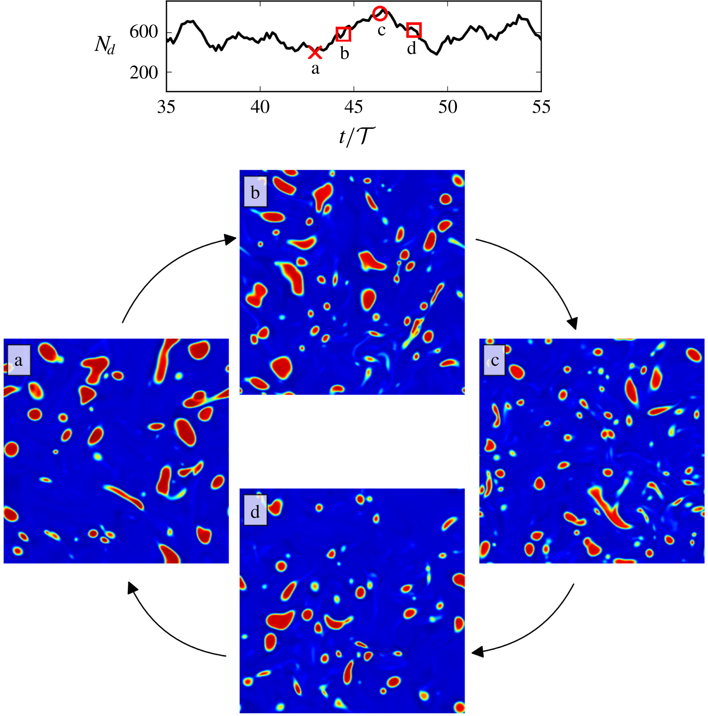
Figure 24. Quasi-periodic evolution of droplet morphology, cyclically visiting a typical state ‘a’ marked by low
 $N_{d}$
(and hence low
$N_{d}$
(and hence low
 $\langle E_{\unicode[STIX]{x1D6FE}}\rangle$
) and high
$\langle E_{\unicode[STIX]{x1D6FE}}\rangle$
) and high
 $\langle E_{k}\rangle$
and state ‘c’ marked by large
$\langle E_{k}\rangle$
and state ‘c’ marked by large
 $N_{d}$
(and
$N_{d}$
(and
 $\langle E_{\unicode[STIX]{x1D6FE}}\rangle$
) and low
$\langle E_{\unicode[STIX]{x1D6FE}}\rangle$
) and low
 $\langle E_{k}\rangle$
. The transition from ‘a’ to ‘c’ happens via a dominance of breakup shown in state ‘b’, while the return from ‘c’ to ‘a’ via state ‘d’ happens due to dominant coalescence. These snapshots are from case T5.
$\langle E_{k}\rangle$
. The transition from ‘a’ to ‘c’ happens via a dominance of breakup shown in state ‘b’, while the return from ‘c’ to ‘a’ via state ‘d’ happens due to dominant coalescence. These snapshots are from case T5.
5.2 Vorticity and interface alignment
Figure 25 shows snapshots of enstrophy from a vertical cross-section of the varying
 $\unicode[STIX]{x1D719}$
simulations (P1–P4), with the droplet contours shown in black. Strong vortical regions are often found in the vicinity of the droplet interface and in the droplet wakes. There is strong interplay between the interfacial dynamics and enstrophy, as high-amplitude vorticity regions align with the interface (Shao et al.
Reference Shao, Luo, Yang and Fan2018) and cause wrinkling. High local dissipative events have also been linked to droplet breakup (Perlekar et al.
Reference Perlekar, Biferale, Sbragaglia, Srivastava and Toschi2012).
$\unicode[STIX]{x1D719}$
simulations (P1–P4), with the droplet contours shown in black. Strong vortical regions are often found in the vicinity of the droplet interface and in the droplet wakes. There is strong interplay between the interfacial dynamics and enstrophy, as high-amplitude vorticity regions align with the interface (Shao et al.
Reference Shao, Luo, Yang and Fan2018) and cause wrinkling. High local dissipative events have also been linked to droplet breakup (Perlekar et al.
Reference Perlekar, Biferale, Sbragaglia, Srivastava and Toschi2012).
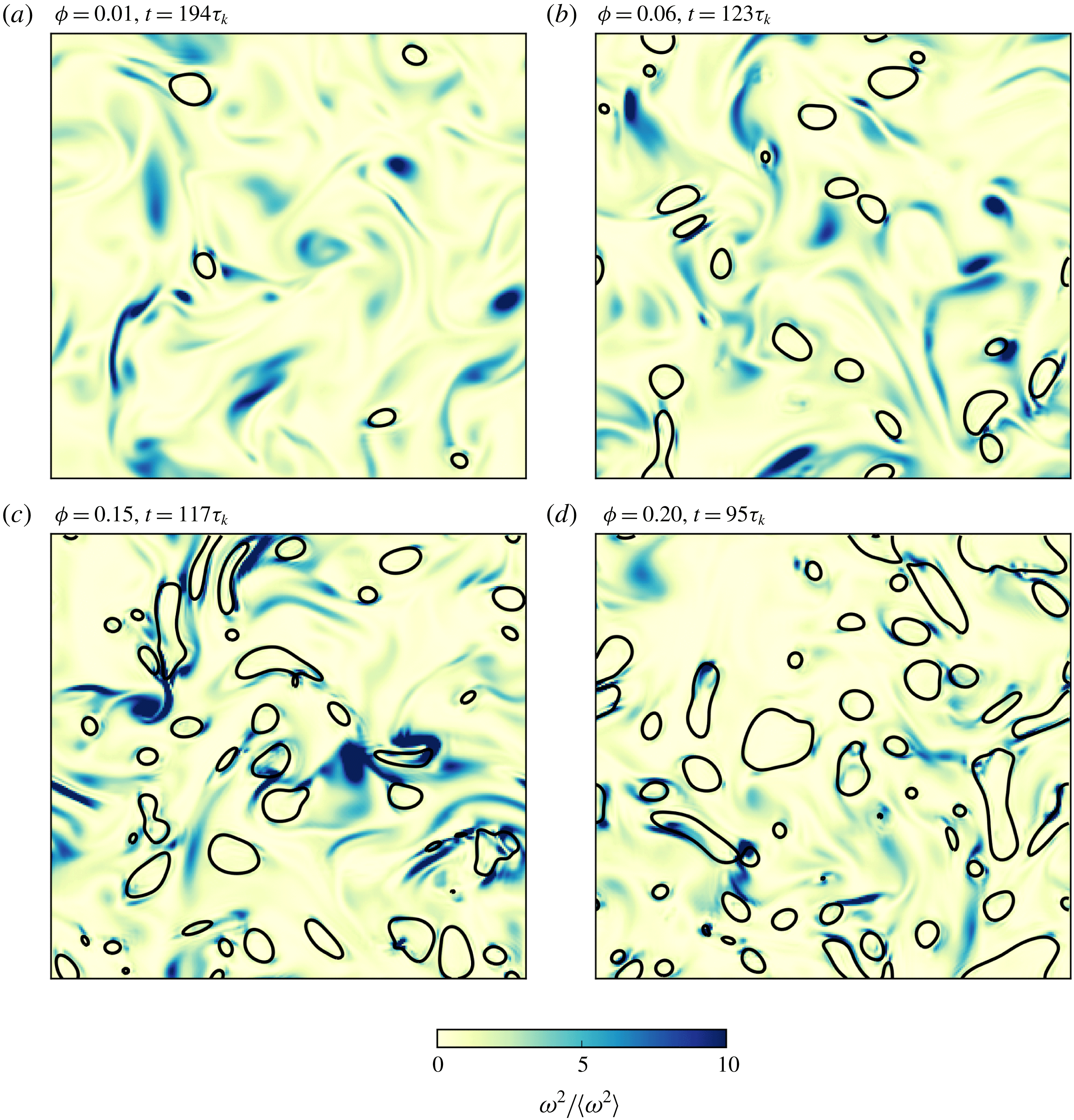
Figure 25. Planar cross-sections (at
 $z=N_{x}/2$
) of the enstrophy field
$z=N_{x}/2$
) of the enstrophy field
 $\unicode[STIX]{x1D714}^{2}$
normalized by the average enstrophy
$\unicode[STIX]{x1D714}^{2}$
normalized by the average enstrophy
 $\langle \unicode[STIX]{x1D714}^{2}\rangle$
along with droplet contours for varying
$\langle \unicode[STIX]{x1D714}^{2}\rangle$
along with droplet contours for varying
 $\unicode[STIX]{x1D719}$
values (cases P1–P4). These snapshots show the typical enstrophy profiles with localized intense vorticity often concentrated around droplet interfaces, which leads to droplet accretion.
$\unicode[STIX]{x1D719}$
values (cases P1–P4). These snapshots show the typical enstrophy profiles with localized intense vorticity often concentrated around droplet interfaces, which leads to droplet accretion.
The interplay between the vorticity vector and the interface normal can be quantified by using the distribution of the cosine of the angle between these two vectors. First, the density field
 $\unicode[STIX]{x1D70C}_{\unicode[STIX]{x1D6FD}}$
is converted to a phase indicator field
$\unicode[STIX]{x1D70C}_{\unicode[STIX]{x1D6FD}}$
is converted to a phase indicator field
 $\unicode[STIX]{x1D713}=(\unicode[STIX]{x1D70C}_{\unicode[STIX]{x1D6FD}}-\unicode[STIX]{x1D70C}_{\unicode[STIX]{x1D6FD}}^{out})/(\unicode[STIX]{x1D70C}_{\unicode[STIX]{x1D6FD}}^{in}-\unicode[STIX]{x1D70C}_{\unicode[STIX]{x1D6FD}}^{out})$
, such that
$\unicode[STIX]{x1D713}=(\unicode[STIX]{x1D70C}_{\unicode[STIX]{x1D6FD}}-\unicode[STIX]{x1D70C}_{\unicode[STIX]{x1D6FD}}^{out})/(\unicode[STIX]{x1D70C}_{\unicode[STIX]{x1D6FD}}^{in}-\unicode[STIX]{x1D70C}_{\unicode[STIX]{x1D6FD}}^{out})$
, such that
 $\unicode[STIX]{x1D713}=1$
in the droplet region,
$\unicode[STIX]{x1D713}=1$
in the droplet region,
 $\unicode[STIX]{x1D713}=0$
in the carrier fluid region and
$\unicode[STIX]{x1D713}=0$
in the carrier fluid region and
 $0<\unicode[STIX]{x1D713}<1$
at the interface. The typical phase indicator gradient then becomes
$0<\unicode[STIX]{x1D713}<1$
at the interface. The typical phase indicator gradient then becomes
 $\unicode[STIX]{x1D735}\unicode[STIX]{x1D713}=1/\unicode[STIX]{x1D701}$
, and the cosine of the orientation angle is calculated where
$\unicode[STIX]{x1D735}\unicode[STIX]{x1D713}=1/\unicode[STIX]{x1D701}$
, and the cosine of the orientation angle is calculated where
 $\unicode[STIX]{x1D735}\unicode[STIX]{x1D713}>0.01\unicode[STIX]{x1D701}$
(where
$\unicode[STIX]{x1D735}\unicode[STIX]{x1D713}>0.01\unicode[STIX]{x1D701}$
(where
 $0.01$
ensures that all of the interfacial regions are considered, while ignoring the bulk regions where
$0.01$
ensures that all of the interfacial regions are considered, while ignoring the bulk regions where
 $\unicode[STIX]{x1D735}\unicode[STIX]{x1D713}=0$
by construction) as follows:
$\unicode[STIX]{x1D735}\unicode[STIX]{x1D713}=0$
by construction) as follows:
 $$\begin{eqnarray}\cos (\unicode[STIX]{x1D703})=\widehat{\boldsymbol{n}}\boldsymbol{\cdot }\widehat{\unicode[STIX]{x1D74E}},\end{eqnarray}$$
where
 $\widehat{\boldsymbol{n}}=\unicode[STIX]{x1D735}\unicode[STIX]{x1D713}/|\unicode[STIX]{x1D735}\unicode[STIX]{x1D713}|$
is the unit normal vector at the interface and
$\widehat{\boldsymbol{n}}=\unicode[STIX]{x1D735}\unicode[STIX]{x1D713}/|\unicode[STIX]{x1D735}\unicode[STIX]{x1D713}|$
is the unit normal vector at the interface and
 $\widehat{\unicode[STIX]{x1D74E}}=\unicode[STIX]{x1D74E}/|\unicode[STIX]{x1D74E}|$
is the normalized vorticity vector.
$\widehat{\unicode[STIX]{x1D74E}}=\unicode[STIX]{x1D74E}/|\unicode[STIX]{x1D74E}|$
is the normalized vorticity vector.
Using this measure, Shao et al. (Reference Shao, Luo, Yang and Fan2018) showed that vorticity tends to align tangentially to droplet interfaces in turbulent flows. Here we extend their result in figure 26 which shows the joint probability distribution of the cosine of the orientation angle
 $\unicode[STIX]{x1D703}$
and the normalized vorticity vector
$\unicode[STIX]{x1D703}$
and the normalized vorticity vector
 $\unicode[STIX]{x1D74E}/\langle \unicode[STIX]{x1D714}^{2}\rangle ^{1/2}$
. The joint probability distribution functions (PDFs) have been generated with statistics collected from six different field snapshots, evenly spaced between roughly
$\unicode[STIX]{x1D74E}/\langle \unicode[STIX]{x1D714}^{2}\rangle ^{1/2}$
. The joint probability distribution functions (PDFs) have been generated with statistics collected from six different field snapshots, evenly spaced between roughly
 $100\unicode[STIX]{x1D70F}_{k}$
–
$100\unicode[STIX]{x1D70F}_{k}$
–
 $200\unicode[STIX]{x1D70F}_{k}$
. The black dashed lines mark
$200\unicode[STIX]{x1D70F}_{k}$
. The black dashed lines mark
 $\unicode[STIX]{x1D714}=0.5\langle \unicode[STIX]{x1D714}^{2}\rangle ^{1/2}$
. Stronger vorticity (
$\unicode[STIX]{x1D714}=0.5\langle \unicode[STIX]{x1D714}^{2}\rangle ^{1/2}$
. Stronger vorticity (
 $\unicode[STIX]{x1D714}>0.5\langle \unicode[STIX]{x1D714}^{2}\rangle ^{1/2}$
) is found to be more prone to align tangentially to the interface. In this range, vorticity is associated with strong swirling motion in the plane orthogonal to the vorticity vector, which causes droplet accretion and subsequent tangential alignment of vorticity with interfaces, yielding
$\unicode[STIX]{x1D714}>0.5\langle \unicode[STIX]{x1D714}^{2}\rangle ^{1/2}$
) is found to be more prone to align tangentially to the interface. In this range, vorticity is associated with strong swirling motion in the plane orthogonal to the vorticity vector, which causes droplet accretion and subsequent tangential alignment of vorticity with interfaces, yielding
 $\cos (\unicode[STIX]{x1D703})=0$
. Weaker vorticity (
$\cos (\unicode[STIX]{x1D703})=0$
. Weaker vorticity (
 $\unicode[STIX]{x1D714}<0.5\langle \unicode[STIX]{x1D714}^{2}\rangle ^{1/2}$
, i.e. below the black dashed line), is incapable of exerting this influence on droplets and hence exhibits a uniform random distribution of orientation angles with respect to the interfaces (as all
$\unicode[STIX]{x1D714}<0.5\langle \unicode[STIX]{x1D714}^{2}\rangle ^{1/2}$
, i.e. below the black dashed line), is incapable of exerting this influence on droplets and hence exhibits a uniform random distribution of orientation angles with respect to the interfaces (as all
 $\unicode[STIX]{x1D703}$
values seem to occur with equal probability at a given
$\unicode[STIX]{x1D703}$
values seem to occur with equal probability at a given
 $\unicode[STIX]{x1D714}$
).
$\unicode[STIX]{x1D714}$
).
Another explanation for this effect could be that most droplets are elongated. It is a known phenomenon that oblate objects align with the vorticity parallel to their axis, as has been shown for sub-Kolmogorov oblate particles (Pumir & Wilkinson Reference Pumir and Wilkinson2011) and inertial spheroids (Roy, Gupta & Ray Reference Roy, Gupta and Ray2018). Since the elongated interfacial regions influence the joint PDF more strongly (by being more prevalent), and since there is a significant peak at
 $\cos (\unicode[STIX]{x1D703})=0$
, the axial alignment mechanism seems plausible. On the other hand, spherical sub-Kolmogorov droplets would tend to spin in local shear of the deep dissipation range and, if deformed, may also tend to have orientation statistics similar to rods in turbulence (Pumir & Wilkinson Reference Pumir and Wilkinson2011). This hypothesis would need to be further tested. Our orientation statistics are valid for droplets in the inertial range, and a simple extrapolation to sub-Kolmogorov droplets cannot be done.
$\cos (\unicode[STIX]{x1D703})=0$
, the axial alignment mechanism seems plausible. On the other hand, spherical sub-Kolmogorov droplets would tend to spin in local shear of the deep dissipation range and, if deformed, may also tend to have orientation statistics similar to rods in turbulence (Pumir & Wilkinson Reference Pumir and Wilkinson2011). This hypothesis would need to be further tested. Our orientation statistics are valid for droplets in the inertial range, and a simple extrapolation to sub-Kolmogorov droplets cannot be done.
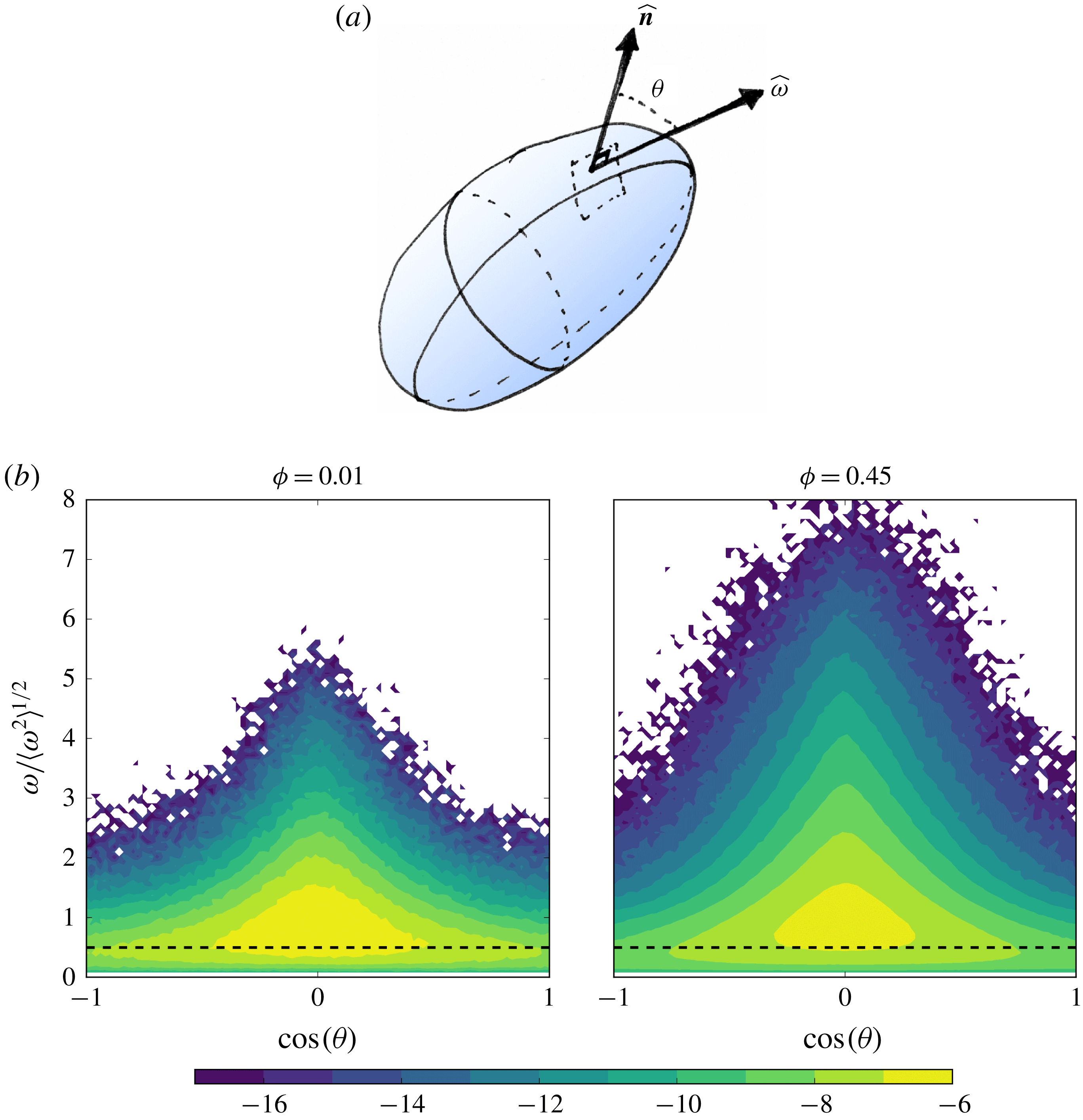
Figure 26. (a) Schematic of the orientation angle
 $\unicode[STIX]{x1D703}$
. Here
$\unicode[STIX]{x1D703}$
. Here
 $\widehat{\boldsymbol{n}}$
is the normal unit vector to the interface and
$\widehat{\boldsymbol{n}}$
is the normal unit vector to the interface and
 $\widehat{\unicode[STIX]{x1D74E}}$
is the vorticity unit vector at that point. (b) Alignment between vorticity and the local interface normal is shown as the joint PDF of the cosine of the angle between them and the magnitude of vorticity, for the two extreme cases of
$\widehat{\unicode[STIX]{x1D74E}}$
is the vorticity unit vector at that point. (b) Alignment between vorticity and the local interface normal is shown as the joint PDF of the cosine of the angle between them and the magnitude of vorticity, for the two extreme cases of
 $\unicode[STIX]{x1D719}=0.01$
(simulation P1) and
$\unicode[STIX]{x1D719}=0.01$
(simulation P1) and
 $\unicode[STIX]{x1D719}=0.45$
(simulation P5), the intermediate cases being in between these two. The contour levels have been logarithmically spaced. Stronger vorticity (
$\unicode[STIX]{x1D719}=0.45$
(simulation P5), the intermediate cases being in between these two. The contour levels have been logarithmically spaced. Stronger vorticity (
 $\unicode[STIX]{x1D714}>0.5\langle \unicode[STIX]{x1D714}^{2}\rangle ^{1/2}$
, above the black dashed lines) tends to align orthogonal to the interface while weaker vorticity remains randomly aligned with the interface with a more uniform distribution.
$\unicode[STIX]{x1D714}>0.5\langle \unicode[STIX]{x1D714}^{2}\rangle ^{1/2}$
, above the black dashed lines) tends to align orthogonal to the interface while weaker vorticity remains randomly aligned with the interface with a more uniform distribution.
5.3 Effect of droplets on flow topology
Local flow topology is described in terms of the three invariants (
 $P$
,
$P$
,
 $Q$
and
$Q$
and
 $R$
) of the velocity gradient tensor
$R$
) of the velocity gradient tensor
 $A_{ij}=\unicode[STIX]{x2202}u_{i}/\unicode[STIX]{x2202}x_{j}$
, which form the coefficients of its characteristic equation
$A_{ij}=\unicode[STIX]{x2202}u_{i}/\unicode[STIX]{x2202}x_{j}$
, which form the coefficients of its characteristic equation
 $$\begin{eqnarray}\unicode[STIX]{x1D706}^{3}+P\unicode[STIX]{x1D706}^{2}+Q\unicode[STIX]{x1D706}+R=0,\end{eqnarray}$$
where
 $P=-A_{ii}$
,
$P=-A_{ii}$
,
 $Q=-A_{ij}A_{ji}/2$
and
$Q=-A_{ij}A_{ji}/2$
and
 $R=-A_{ij}A_{jk}A_{ki}/3$
. For incompressible flow,
$R=-A_{ij}A_{jk}A_{ki}/3$
. For incompressible flow,
 $P=0$
(i.e. the sum of the eigenvalues). In the
$P=0$
(i.e. the sum of the eigenvalues). In the
 $P=0$
plane (or the
$P=0$
plane (or the
 $QR$
-plane), turbulent flow of diverse kinds produces a teardrop-like profile for the joint probability distribution of
$QR$
-plane), turbulent flow of diverse kinds produces a teardrop-like profile for the joint probability distribution of
 $Q$
and
$Q$
and
 $R$
with four distinct flow topologies that have been illustrated in figure 27 (adapted from Ooi et al. (Reference Ooi, Martin, Soria and Chong1999)). The curve
$R$
with four distinct flow topologies that have been illustrated in figure 27 (adapted from Ooi et al. (Reference Ooi, Martin, Soria and Chong1999)). The curve
 $D=27R^{2}/4+Q^{3}=0$
(derivation can be found in Chong, Perry & Cantwell (Reference Chong, Perry and Cantwell1990)) divides the region with three real eigenvalues of
$D=27R^{2}/4+Q^{3}=0$
(derivation can be found in Chong, Perry & Cantwell (Reference Chong, Perry and Cantwell1990)) divides the region with three real eigenvalues of
 $A_{ij}$
(below, where
$A_{ij}$
(below, where
 $D<0$
) from the region with one real and a pair of complex conjugate eigenvalues (above, where
$D<0$
) from the region with one real and a pair of complex conjugate eigenvalues (above, where
 $D>0$
). The most dominant flow features are stable focus stretching ‘SFS’ (i.e. vortex stretching) and unstable-node/saddle/saddle ‘UN/S/S’ (i.e. bi-axial straining (Chacin & Cantwell Reference Chacin and Cantwell2000)). Also, ‘UFC’ corresponds to unstable focus compression (or vortex compression) and ‘SN/S/S’ is stable-node/saddle/saddle (or axial straining).
$D>0$
). The most dominant flow features are stable focus stretching ‘SFS’ (i.e. vortex stretching) and unstable-node/saddle/saddle ‘UN/S/S’ (i.e. bi-axial straining (Chacin & Cantwell Reference Chacin and Cantwell2000)). Also, ‘UFC’ corresponds to unstable focus compression (or vortex compression) and ‘SN/S/S’ is stable-node/saddle/saddle (or axial straining).
Figure 27. The four distinct flow topologies of turbulent flow shown in the plane of
 $Q$
and
$Q$
and
 $R$
, i.e. the second and third invariants of the velocity gradient tensor
$R$
, i.e. the second and third invariants of the velocity gradient tensor
 $A_{ij}$
. ‘SFS’ is stable focus stretching, ‘UFC’ is unstable focus compression, ‘SN/S/S’ is stable-node/saddle/saddle and ‘UN/S/S’ is unstable-node/saddle/saddle. This figure is an adaptation from the classification in Ooi et al. (Reference Ooi, Martin, Soria and Chong1999).
$A_{ij}$
. ‘SFS’ is stable focus stretching, ‘UFC’ is unstable focus compression, ‘SN/S/S’ is stable-node/saddle/saddle and ‘UN/S/S’ is unstable-node/saddle/saddle. This figure is an adaptation from the classification in Ooi et al. (Reference Ooi, Martin, Soria and Chong1999).
The presence of droplets or particles which interact with the flow can modify the distribution of flow topologies, which is a modification of turbulence structure at a more local and fundamental level than for instance modifications to the kinetic energy spectrum. This has been well investigated for particle-laden turbulence (Rouson & Eaton Reference Rouson and Eaton2001; Bijlard et al. Reference Bijlard, Oliemans, Portela and Ooms2010) and recently shown for elastic polymers in turbulence by Perlekar, Mitra & Pandit (Reference Perlekar, Mitra and Pandit2010). Although polymer additives are fundamentally very different from droplets, both are elastic objects, and hence they may have some similar turbulence modification effects. Recently, Shao et al. (Reference Shao, Luo, Yang and Fan2018) showed a mild suppression of bi-axial straining in droplet-laden turbulence upon changing the Weber number.
How droplets modify flow topology has not fully been investigated so far. Here, we first show the influence of increasing dispersed-phase volume fraction on the
 $QR$
profiles calculated using simulations P1–P5. Since
$QR$
profiles calculated using simulations P1–P5. Since
 $Re_{\unicode[STIX]{x1D706}}$
for these cases varies (and is almost a factor 2 lower than the corresponding single-phase turbulence simulation, see table 1), the normalization factor
$Re_{\unicode[STIX]{x1D706}}$
for these cases varies (and is almost a factor 2 lower than the corresponding single-phase turbulence simulation, see table 1), the normalization factor
 $\langle Q_{w}\rangle =\langle \unicode[STIX]{x1D714}^{2}\rangle /4$
(Ooi et al.
Reference Ooi, Martin, Soria and Chong1999) is calculated for each case separately. This allows us to focus on the modification of flow features alone, without comparing the magnitude of these extreme
$\langle Q_{w}\rangle =\langle \unicode[STIX]{x1D714}^{2}\rangle /4$
(Ooi et al.
Reference Ooi, Martin, Soria and Chong1999) is calculated for each case separately. This allows us to focus on the modification of flow features alone, without comparing the magnitude of these extreme
 $QR$
events. Figure 28 shows the
$QR$
events. Figure 28 shows the
 $QR$
field sampled over the entire multiphase velocity field. For case (b)
$QR$
field sampled over the entire multiphase velocity field. For case (b)
 $\unicode[STIX]{x1D719}=0.01$
, the profile is narrower than for single-phase turbulence, case (a), although the overall shape is similar. This might be due to the
$\unicode[STIX]{x1D719}=0.01$
, the profile is narrower than for single-phase turbulence, case (a), although the overall shape is similar. This might be due to the
 $\unicode[STIX]{x1D719}=0.01$
dispersion being dilute, which makes coalescence infrequent. Overall, in this case, the flow field is similar to that in single-phase turbulence, and coalescence-generated smaller-scale features are rare. This seems likely, as at successively higher volume fractions, cases (c) to (f), the
$\unicode[STIX]{x1D719}=0.01$
dispersion being dilute, which makes coalescence infrequent. Overall, in this case, the flow field is similar to that in single-phase turbulence, and coalescence-generated smaller-scale features are rare. This seems likely, as at successively higher volume fractions, cases (c) to (f), the
 $QR$
profile is influenced more significantly and it tends to become more symmetric across the
$QR$
profile is influenced more significantly and it tends to become more symmetric across the
 $R=0$
line. This follows from an increase in the axial straining part of the flow, along with an extension of the profile into the
$R=0$
line. This follows from an increase in the axial straining part of the flow, along with an extension of the profile into the
 $D>0$
and
$D>0$
and
 $R>0$
region which shows a relative increase in vortex compression as opposed to vortex stretching (
$R>0$
region which shows a relative increase in vortex compression as opposed to vortex stretching (
 $D>0$
and
$D>0$
and
 $R<0$
).
$R<0$
).
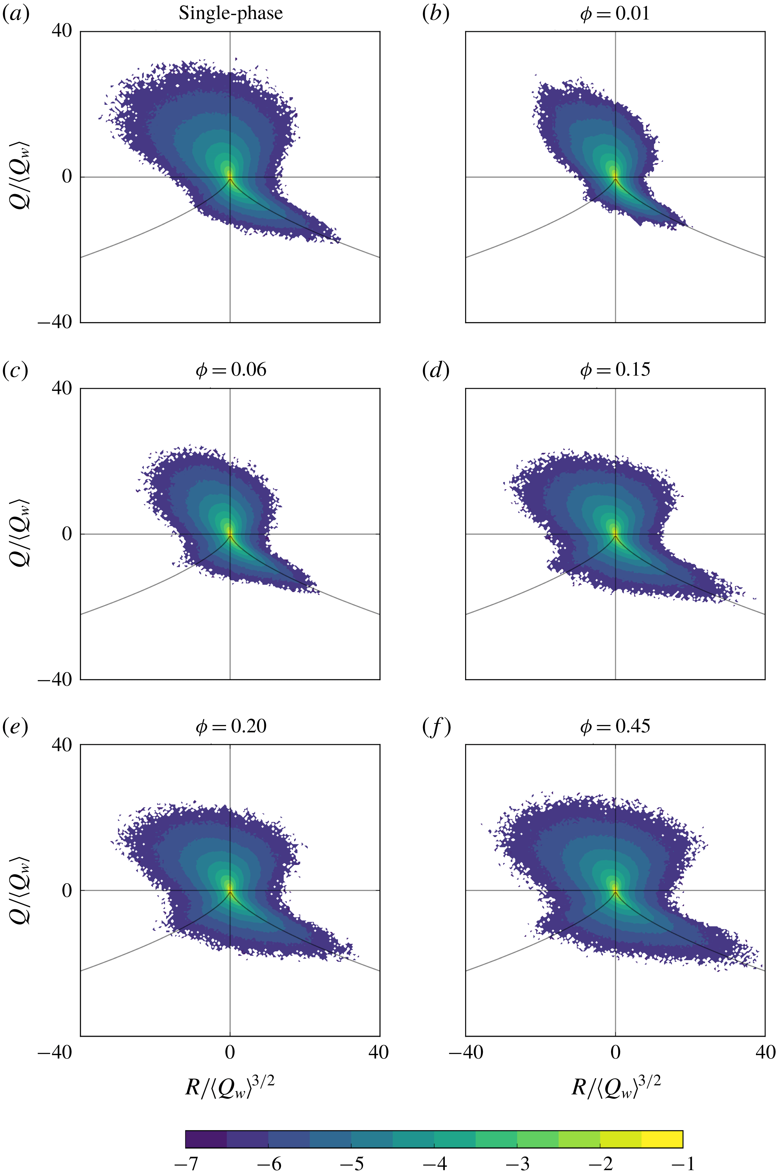
Figure 28. Joint PDFs of the second and third invariants (
 $Q$
and
$Q$
and
 $R$
) of the velocity gradient tensor show the typical teardrop profile characteristic of single-phase turbulence being modified into a more symmetric profile with an increase in axial straining and vortex compression. Here
$R$
) of the velocity gradient tensor show the typical teardrop profile characteristic of single-phase turbulence being modified into a more symmetric profile with an increase in axial straining and vortex compression. Here
 $\langle Q_{w}\rangle =\langle \unicode[STIX]{x1D714}^{2}\rangle /4$
and the quantities are calculated over the entire multiphase velocity field, sampled at five time instances separated by
$\langle Q_{w}\rangle =\langle \unicode[STIX]{x1D714}^{2}\rangle /4$
and the quantities are calculated over the entire multiphase velocity field, sampled at five time instances separated by
 $20\unicode[STIX]{x1D70F}_{k}$
. The solid lines mark
$20\unicode[STIX]{x1D70F}_{k}$
. The solid lines mark
 $Q=0$
,
$Q=0$
,
 $R=0$
and
$R=0$
and
 $D=27R^{2}/4+Q^{3}=0$
, and the contour levels have been logarithmically spaced.
$D=27R^{2}/4+Q^{3}=0$
, and the contour levels have been logarithmically spaced.
Modification of the
 $QR$
profile due to an increase in
$QR$
profile due to an increase in
 $\unicode[STIX]{x1D719}$
hints that it is a consequence of turbulence being constrained by the dispersed phase. To validate this claim, in figure 29 the
$\unicode[STIX]{x1D719}$
hints that it is a consequence of turbulence being constrained by the dispersed phase. To validate this claim, in figure 29 the
 $QR$
profiles are shown while being sampled inside and outside the droplet regions (marked as ‘d’ for droplet phase and ‘c’ for continuous phase). This has been done for simulations D4 and D5 (which have the highest resolution and significantly different
$QR$
profiles are shown while being sampled inside and outside the droplet regions (marked as ‘d’ for droplet phase and ‘c’ for continuous phase). This has been done for simulations D4 and D5 (which have the highest resolution and significantly different
 $Re_{\unicode[STIX]{x1D706}}=30$
and
$Re_{\unicode[STIX]{x1D706}}=30$
and
 $118$
respectively). The
$118$
respectively). The
 $QR$
profiles have been sampled at five time instances separated by
$QR$
profiles have been sampled at five time instances separated by
 $100\unicode[STIX]{x1D70F}_{k}$
. The difference between the flow topology in the droplet and continuous phase is striking, where within the droplet region the
$100\unicode[STIX]{x1D70F}_{k}$
. The difference between the flow topology in the droplet and continuous phase is striking, where within the droplet region the
 $QR$
profile seems to almost have flipped across the
$QR$
profile seems to almost have flipped across the
 $R=0$
axis.
$R=0$
axis.
There is a small increase in axial straining and a significant increase in vortex compression inside the droplets. A possible explanation for this effect could be the presence of interfaces surrounding droplets which behave like elastic surfaces. Vortices being stretched inside the droplets will try to elongate the droplet along the stretching axis, and this will be counteracted by interfacial tension which would instead tend to compress vortices. Since vortex compression contributes to energy dissipation (Tsinober Reference Tsinober2009), an enhancement of energy dissipation might also be expected inside droplets from these results (further investigation of this is left for future work). With a similar reasoning, increase in axial straining may also be an effect of surface tension. Axial strain tends to stretch droplets into prolate ellipsoids (cigar-like objects), while bi-axial strain would shape them into oblate ellipsoids (flat pancake-like objects). For equivalent strain intensity, bi-axial strain would lead to a more rapid increase in surface energy than axial strain. The increase in axial strain may hence be another consequence of droplets trying to minimize surface energy. More work is required to pinpoint the reason behind the droplet effects on flow topology. These effects, along with the alignment of elongated droplets parallel to local vorticity, can be viewed as complementary phenomena. The continuous-phase
 $QR$
profile remains mostly tear-drop like, with minor increase in axial straining and vortex compression.
$QR$
profile remains mostly tear-drop like, with minor increase in axial straining and vortex compression.
We did not directly investigate the effect of surface tension on the
 $QR$
profiles, but it can be argued that an increase in surface tension will further amplify vortex compression and axial strain (if our hypothesis of the mechanism is correct). This is because a higher
$QR$
profiles, but it can be argued that an increase in surface tension will further amplify vortex compression and axial strain (if our hypothesis of the mechanism is correct). This is because a higher
 $\unicode[STIX]{x1D6FE}$
will lead to a stronger surface tension force which will counteract any increase in surface area due to deformation or breakup. At the limit of zero surface tension both fluids will perfectly mix and one will recover the usual tear-drop like
$\unicode[STIX]{x1D6FE}$
will lead to a stronger surface tension force which will counteract any increase in surface area due to deformation or breakup. At the limit of zero surface tension both fluids will perfectly mix and one will recover the usual tear-drop like
 $QR$
profile found for single-phase turbulence. This can also be related to the effect of the average droplet size, where a higher surface tension will lead to larger droplets on average, which will influence turbulence topology more than small droplets. Hints of this effect are visible in results from the increasing volume fraction simulations, where on average the droplet sizes increase, which results in greater turbulence modification. A direct comparison, however, has not been performed in this study, and it would require larger droplet sizes while keeping the volume fraction and turbulence intensity the same.
$QR$
profile found for single-phase turbulence. This can also be related to the effect of the average droplet size, where a higher surface tension will lead to larger droplets on average, which will influence turbulence topology more than small droplets. Hints of this effect are visible in results from the increasing volume fraction simulations, where on average the droplet sizes increase, which results in greater turbulence modification. A direct comparison, however, has not been performed in this study, and it would require larger droplet sizes while keeping the volume fraction and turbulence intensity the same.

Figure 29. Joint PDFs of
 $QR$
sampled in the droplet phase (‘d’) and continuous phase (‘c’) for cases D4 and D5. The
$QR$
sampled in the droplet phase (‘d’) and continuous phase (‘c’) for cases D4 and D5. The
 $QR$
profile appears to flip on the
$QR$
profile appears to flip on the
 $R=0$
axis for the droplet phase, with a striking increase in vortex compression and axial straining. The continuous phase
$R=0$
axis for the droplet phase, with a striking increase in vortex compression and axial straining. The continuous phase
 $QR$
profile remains mostly tear-drop like with minor increase in axial straining.
$QR$
profile remains mostly tear-drop like with minor increase in axial straining.
6 Conclusions
We perform direct numerical simulations of emulsions under homogeneous isotropic turbulence conditions performed by using the pseudopotential lattice-Boltzmann method. New findings on droplet size distributions, multiphase kinetic energy spectra, coupled kinetic energy and droplet number density dynamics, interface–dissipation interactions and modification of turbulence flow topology in emulsions are reported.
The process of dispersion formation is investigated for varying volume fractions of the dispersed phase and varying turbulence intensities for an emulsion with a density and viscosity ratio of 1. Using an appropriate set of parameters (such that the pseudopotential repulsive force between components dominates the local turbulence force), the effect of droplet dissolution is mitigated, an issue that was found limiting in previous work (Perlekar et al. Reference Perlekar, Biferale, Sbragaglia, Srivastava and Toschi2012; Komrakova et al. Reference Komrakova, Eskin and Derksen2015a ). While further maintaining spurious currents to well below the physical velocity scales, the multiphase kinetic energy spectra were shown to exhibit signatures of breakup and coalescence at wavenumbers smaller and larger than the inverse Hinze scale respectively.
At small wavenumbers, energy is primarily extracted from the flow, where a higher dispersed-phase volume fraction
 $\unicode[STIX]{x1D719}$
extracts more energy due to the profusion of interfaces. At large wavenumbers, for successively higher
$\unicode[STIX]{x1D719}$
extracts more energy due to the profusion of interfaces. At large wavenumbers, for successively higher
 $\unicode[STIX]{x1D719}$
, the energy content of the dissipation range increases due to more frequent coalescence which generates smaller-scale motions. The droplet distribution is shown to follow the
$\unicode[STIX]{x1D719}$
, the energy content of the dissipation range increases due to more frequent coalescence which generates smaller-scale motions. The droplet distribution is shown to follow the
 $d^{-10/3}$
scaling that has been previously found for purely inertial breakup of the dispersed phase (Garrett et al.
Reference Garrett, Li and Farmer2000; Deane & Stokes Reference Deane and Stokes2002). High volume fraction dispersions under moderate turbulence intensities do not exhibit the
$d^{-10/3}$
scaling that has been previously found for purely inertial breakup of the dispersed phase (Garrett et al.
Reference Garrett, Li and Farmer2000; Deane & Stokes Reference Deane and Stokes2002). High volume fraction dispersions under moderate turbulence intensities do not exhibit the
 $k^{-5/3}$
inertial range scaling, and in these cases coalescence cannot be ignored either, in which case the classical Hinze (Reference Hinze1955) scale becomes invalid. We propose a generalization of the Hinze scale for these situations, where instead of using the dissipation rate
$k^{-5/3}$
inertial range scaling, and in these cases coalescence cannot be ignored either, in which case the classical Hinze (Reference Hinze1955) scale becomes invalid. We propose a generalization of the Hinze scale for these situations, where instead of using the dissipation rate
 $\langle \unicode[STIX]{x1D716}\rangle$
to determine the characteristic velocity at the droplet scale
$\langle \unicode[STIX]{x1D716}\rangle$
to determine the characteristic velocity at the droplet scale
 $d$
, we use the multiphase kinetic energy spectra
$d$
, we use the multiphase kinetic energy spectra
 $\langle E(k)\rangle$
(which reflects the average energetics including coalescence and breakup at each scale) and the droplet wavenumber
$\langle E(k)\rangle$
(which reflects the average energetics including coalescence and breakup at each scale) and the droplet wavenumber
 $k_{d}$
. This gives a Weber number spectrum
$k_{d}$
. This gives a Weber number spectrum
 $We(k)$
, which in turn can be used as an indication for the lengthscale at which inertia and surface tension become comparable (i.e.
$We(k)$
, which in turn can be used as an indication for the lengthscale at which inertia and surface tension become comparable (i.e.
 $We(k)\approx 1$
, or
$We(k)\approx 1$
, or
 $We(k)\approx We_{crit}$
if the critical Weber number is known). This criterion was found to predict the lengthscale at which the droplet distribution transitions into the
$We(k)\approx We_{crit}$
if the critical Weber number is known). This criterion was found to predict the lengthscale at which the droplet distribution transitions into the
 $d^{-10/3}$
scaling reasonably well, which is known to hold in the breakup-dominated range of scales (Deane & Stokes Reference Deane and Stokes2002). Our criterion also reduces to the classical Hinze scale when
$d^{-10/3}$
scaling reasonably well, which is known to hold in the breakup-dominated range of scales (Deane & Stokes Reference Deane and Stokes2002). Our criterion also reduces to the classical Hinze scale when
 $E(k)$
is of the Kolmogorov form, i.e.
$E(k)$
is of the Kolmogorov form, i.e.
 $E(k)\sim \unicode[STIX]{x1D716}^{2/3}k^{-5/3}$
.
$E(k)\sim \unicode[STIX]{x1D716}^{2/3}k^{-5/3}$
.
The importance of the relative resolution between the various lengthscales that govern turbulence droplet simulations is emphasized. We show that it is important to resolve
 $N_{x}>{\mathcal{L}}$
to correctly capture droplet deformation and breakup at relatively weaker turbulence intensities and high volume fractions, where otherwise the droplet fluid can form a complex tangle of elongated filaments as the maximum droplet deformation becomes unresolved. We also maintain
$N_{x}>{\mathcal{L}}$
to correctly capture droplet deformation and breakup at relatively weaker turbulence intensities and high volume fractions, where otherwise the droplet fluid can form a complex tangle of elongated filaments as the maximum droplet deformation becomes unresolved. We also maintain
 ${\mathcal{L}}\gg d\gg \unicode[STIX]{x1D702}$
, such that the droplets interact mainly with the inertial range of turbulence.
${\mathcal{L}}\gg d\gg \unicode[STIX]{x1D702}$
, such that the droplets interact mainly with the inertial range of turbulence.
In line with recent results (Shao et al.
Reference Shao, Luo, Yang and Fan2018), vorticity is shown to strongly align tangentially to droplet interfaces. This effect was shown to be stronger for higher vorticity magnitudes. The presence of dispersed phase is also shown to significantly alter the flow topology represented by the joint PDF of
 $QR$
, i.e. the second and third invariants of the velocity gradient tensor, much more acutely than recognized (Shao et al.
Reference Shao, Luo, Yang and Fan2018). The well-known tear-drop-like profile becomes almost flipped across the
$QR$
, i.e. the second and third invariants of the velocity gradient tensor, much more acutely than recognized (Shao et al.
Reference Shao, Luo, Yang and Fan2018). The well-known tear-drop-like profile becomes almost flipped across the
 $R=0$
axis when sampled inside the droplet in comparison to sampling in the carrier phase. A striking increase in axial straining and vortex compression is found in the droplets, which hints at an interplay of interfacial tension with turbulence, where droplets try to minimize any increase in surface energy by suppressing flow types that cause more deformation – namely bi-axial straining and vortex stretching. This result hints that droplets might have enhanced dissipation in their interior. The carrier-fluid topology retains features of the well-known tear-drop profile (Chacin & Cantwell Reference Chacin and Cantwell2000) with only minor increase in axial straining and vortex compression.
$R=0$
axis when sampled inside the droplet in comparison to sampling in the carrier phase. A striking increase in axial straining and vortex compression is found in the droplets, which hints at an interplay of interfacial tension with turbulence, where droplets try to minimize any increase in surface energy by suppressing flow types that cause more deformation – namely bi-axial straining and vortex stretching. This result hints that droplets might have enhanced dissipation in their interior. The carrier-fluid topology retains features of the well-known tear-drop profile (Chacin & Cantwell Reference Chacin and Cantwell2000) with only minor increase in axial straining and vortex compression.
Last but not the least, we show for the first time the dynamics of the quasi-equilibrium between coalescence and breakup under constant energy input to the system which leads to sustained turbulence over very long simulation times (around
 $100{\mathcal{T}}$
). This state is often called a ‘steady state’, although the dynamics more closely resembles a limit cycle in the state-space of kinetic energy
$100{\mathcal{T}}$
). This state is often called a ‘steady state’, although the dynamics more closely resembles a limit cycle in the state-space of kinetic energy
 $\langle E_{k}\rangle$
, enstrophy
$\langle E_{k}\rangle$
, enstrophy
 $\langle \unicode[STIX]{x1D714}^{2}\rangle$
, droplet number density
$\langle \unicode[STIX]{x1D714}^{2}\rangle$
, droplet number density
 $N_{d}$
and surface energy
$N_{d}$
and surface energy
 $\langle E_{\unicode[STIX]{x1D6FE}}\rangle$
. The extreme values of
$\langle E_{\unicode[STIX]{x1D6FE}}\rangle$
. The extreme values of
 $\langle E_{k}\rangle$
are manifested in the
$\langle E_{k}\rangle$
are manifested in the
 $\langle \unicode[STIX]{x1D714}^{2}\rangle$
evolution with a certain time delay, which then again show up in the
$\langle \unicode[STIX]{x1D714}^{2}\rangle$
evolution with a certain time delay, which then again show up in the
 $N_{d}$
evolution leading to a time-delayed dynamics. The dispersion oscillates between two morphologies, the journey between them being mediated by alternating bouts of dominant breakup and coalescence. Surface energy was found to peak prior to droplet breakup, reflecting the underlying breakup mechanism which involves the stretching of droplet fluid filaments, which have a higher surface area than the subsequently formed daughter droplets.
$N_{d}$
evolution leading to a time-delayed dynamics. The dispersion oscillates between two morphologies, the journey between them being mediated by alternating bouts of dominant breakup and coalescence. Surface energy was found to peak prior to droplet breakup, reflecting the underlying breakup mechanism which involves the stretching of droplet fluid filaments, which have a higher surface area than the subsequently formed daughter droplets.
We believe that this time-delayed dynamics will be found in localized regions of much larger droplet-laden systems, where the overall system may not exhibit significant fluctuations in state-space variables, as the localized fluctuations would cancel each other. However, in smaller, finite systems (as prevalent in turbulence-resolving droplet-laden simulations (Elghobashi Reference Elghobashi2019)), this can be an important consideration, as the ‘steady state’ can have its own interesting dynamics. These considerations of delayed temporal dynamics may also be relevant to developing more realistic breakup and coalescence kernels that currently correlate state-space variables instantaneously (Sajjadi et al. Reference Sajjadi, Raman, Shah and Ibrahim2013), which we have not explored given the limits of the current work.
Further investigation of the system evolution in the
 $\langle E_{k}\rangle$
–
$\langle E_{k}\rangle$
–
 $\langle E_{\unicode[STIX]{x1D6FE}}\rangle$
phase space would help describe the exact exchange of energy, where the effects of coalescence and breakup would need to be isolated. This may be done by simulating larger droplets in weak turbulence, which would correspond to a detailed view of individual droplets near the dissipation range, and it is something we wish to investigate in the future.
$\langle E_{\unicode[STIX]{x1D6FE}}\rangle$
phase space would help describe the exact exchange of energy, where the effects of coalescence and breakup would need to be isolated. This may be done by simulating larger droplets in weak turbulence, which would correspond to a detailed view of individual droplets near the dissipation range, and it is something we wish to investigate in the future.
We hope that this paper brings to attention the avenue of considering the details of resolved simulations from different perspectives (as we have attempted, while considering the limitations of our work). This helps reinforce our understanding of the phenomena at different levels. A statistical perspective (looking at spectra, time-averaged quantities etc) helps with an overall description, while a dynamical systems perspective on the state-space helps pave the way for deciphering the true mediation of cause and effect such as droplet–dissipation interactions and the modification of turbulence due to droplets, which we are only now beginning to understand.
Acknowledgements
S.M. would like to thank Professor J. Derksen (University of Aberdeen) for his suggestions during the early part of this research, and Dr J. Picardo (International Center for Theoretical Sciences, Bangalore) and Dr L. Portela (TU Delft) for many insightful discussions regarding the results. This work is funded by the Institute for Sustainable Process Technology (ISPT), the Netherlands.
Appendix
In this appendix we briefly discuss the segmentation of droplets. The simulations output a continuous density field for both components
 $\unicode[STIX]{x1D6FC}$
and
$\unicode[STIX]{x1D6FC}$
and
 $\unicode[STIX]{x1D6FD}$
. As mentioned, the density variation of a component indicates the presence of droplets, where the density of component
$\unicode[STIX]{x1D6FD}$
. As mentioned, the density variation of a component indicates the presence of droplets, where the density of component
 $\unicode[STIX]{x1D6FD}$
inside the droplet
$\unicode[STIX]{x1D6FD}$
inside the droplet
 $\unicode[STIX]{x1D70C}_{\unicode[STIX]{x1D6FD}}^{in}\approx 4.4$
and that outside the droplet
$\unicode[STIX]{x1D70C}_{\unicode[STIX]{x1D6FD}}^{in}\approx 4.4$
and that outside the droplet
 $\unicode[STIX]{x1D70C}_{\unicode[STIX]{x1D6FD}}^{out}\approx 0.4~[\text{lu}]$
when the flow is fully developed. The droplet identification is done by fixing a threshold density value
$\unicode[STIX]{x1D70C}_{\unicode[STIX]{x1D6FD}}^{out}\approx 0.4~[\text{lu}]$
when the flow is fully developed. The droplet identification is done by fixing a threshold density value
 $\unicode[STIX]{x1D70C}^{c}$
. Every contiguous droplet-fluid region, i.e. a cluster of neighbouring lattice cells with values above the chosen threshold (
$\unicode[STIX]{x1D70C}^{c}$
. Every contiguous droplet-fluid region, i.e. a cluster of neighbouring lattice cells with values above the chosen threshold (
 $\unicode[STIX]{x1D70C}_{\unicode[STIX]{x1D6FD}}>\unicode[STIX]{x1D70C}^{c}$
), is identified as a droplet. For a point
$\unicode[STIX]{x1D70C}_{\unicode[STIX]{x1D6FD}}>\unicode[STIX]{x1D70C}^{c}$
), is identified as a droplet. For a point
 $(i,j,k)$
, only the six neighbours
$(i,j,k)$
, only the six neighbours
 $(i\pm 1,j\pm 1,k\pm 1)$
are considered in our spatial segmentation (or clustering) algorithm, which was originally developed by Siebesma & Jonker (Reference Siebesma and Jonker2000). This is a post-processing step with a single parameter
$(i\pm 1,j\pm 1,k\pm 1)$
are considered in our spatial segmentation (or clustering) algorithm, which was originally developed by Siebesma & Jonker (Reference Siebesma and Jonker2000). This is a post-processing step with a single parameter
 $\unicode[STIX]{x1D70C}_{c}$
, which gives the total number of droplets in the system
$\unicode[STIX]{x1D70C}_{c}$
, which gives the total number of droplets in the system
 $N_{d}$
, the individual droplet volumes
$N_{d}$
, the individual droplet volumes
 $V$
(and equivalent diameters
$V$
(and equivalent diameters
 $d=(6V/\unicode[STIX]{x03C0})^{1/3}$
), the droplet surface area
$d=(6V/\unicode[STIX]{x03C0})^{1/3}$
), the droplet surface area
 $S_{A}$
and the droplet centre of mass. These results should not significantly depend on the choice of
$S_{A}$
and the droplet centre of mass. These results should not significantly depend on the choice of
 $\unicode[STIX]{x1D70C}^{c}$
.
$\unicode[STIX]{x1D70C}^{c}$
.
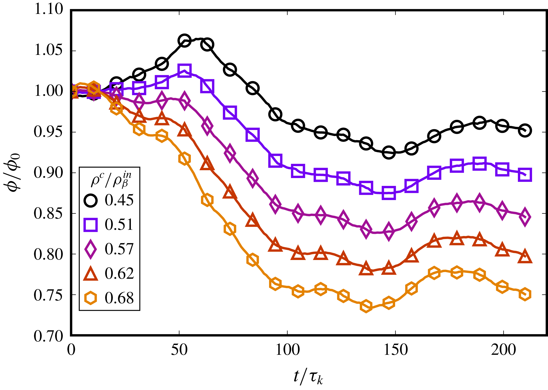
Figure 30. Normalized phase fraction evolution for varying
 $\unicode[STIX]{x1D70C}^{c}$
used to segment droplets. Here
$\unicode[STIX]{x1D70C}^{c}$
used to segment droplets. Here
 $\unicode[STIX]{x1D70C}^{c}$
is reported as a fraction of
$\unicode[STIX]{x1D70C}^{c}$
is reported as a fraction of
 $\unicode[STIX]{x1D70C}_{\unicode[STIX]{x1D6FD}}^{in}$
, while
$\unicode[STIX]{x1D70C}_{\unicode[STIX]{x1D6FD}}^{in}$
, while
 $\unicode[STIX]{x1D70C}_{\unicode[STIX]{x1D6FD}}^{out}/\unicode[STIX]{x1D70C}_{\unicode[STIX]{x1D6FD}}^{in}=0.1$
, therefore the useful range of
$\unicode[STIX]{x1D70C}_{\unicode[STIX]{x1D6FD}}^{out}/\unicode[STIX]{x1D70C}_{\unicode[STIX]{x1D6FD}}^{in}=0.1$
, therefore the useful range of
 $\unicode[STIX]{x1D70C}^{c}/\unicode[STIX]{x1D70C}_{\unicode[STIX]{x1D6FD}}^{in}$
is
$\unicode[STIX]{x1D70C}^{c}/\unicode[STIX]{x1D70C}_{\unicode[STIX]{x1D6FD}}^{in}$
is
 $0.1$
to
$0.1$
to
 $1.0$
, and
$1.0$
, and
 $\unicode[STIX]{x1D70C}^{c}/\unicode[STIX]{x1D70C}_{\unicode[STIX]{x1D6FD}}^{in}=0.55$
is halfway.
$\unicode[STIX]{x1D70C}^{c}/\unicode[STIX]{x1D70C}_{\unicode[STIX]{x1D6FD}}^{in}=0.55$
is halfway.
As the dispersed-phase density values within the interface vary between
 $0.1\unicode[STIX]{x1D70C}_{\unicode[STIX]{x1D6FD}}^{in}\leqslant \unicode[STIX]{x1D70C}_{\unicode[STIX]{x1D6FD}}\leqslant \unicode[STIX]{x1D70C}_{\unicode[STIX]{x1D6FD}}^{in}$
, the useful range of thresholding values
$0.1\unicode[STIX]{x1D70C}_{\unicode[STIX]{x1D6FD}}^{in}\leqslant \unicode[STIX]{x1D70C}_{\unicode[STIX]{x1D6FD}}\leqslant \unicode[STIX]{x1D70C}_{\unicode[STIX]{x1D6FD}}^{in}$
, the useful range of thresholding values
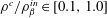 $\unicode[STIX]{x1D70C}^{c}/\unicode[STIX]{x1D70C}_{\unicode[STIX]{x1D6FD}}^{in}\in [0.1,1.0]$
, as
$\unicode[STIX]{x1D70C}^{c}/\unicode[STIX]{x1D70C}_{\unicode[STIX]{x1D6FD}}^{in}\in [0.1,1.0]$
, as
 $\unicode[STIX]{x1D70C}^{c}$
should lie within the interface. Figure 30 shows the relative evolution of the volume fraction over time for the case
$\unicode[STIX]{x1D70C}^{c}$
should lie within the interface. Figure 30 shows the relative evolution of the volume fraction over time for the case
 $\unicode[STIX]{x1D719}=0.06$
, for different threshold values around the middle of the usable range. Lower values of
$\unicode[STIX]{x1D719}=0.06$
, for different threshold values around the middle of the usable range. Lower values of
 $\unicode[STIX]{x1D70C}^{c}$
account for more of the dispersed phase as droplets, which is why the total volume fraction increases as
$\unicode[STIX]{x1D70C}^{c}$
account for more of the dispersed phase as droplets, which is why the total volume fraction increases as
 $\unicode[STIX]{x1D70C}^{c}$
decreases. Note that this is not a physical increase in volume fraction (as the density field is determined by the dynamics alone) and is only a post-processing estimate – as
$\unicode[STIX]{x1D70C}^{c}$
decreases. Note that this is not a physical increase in volume fraction (as the density field is determined by the dynamics alone) and is only a post-processing estimate – as
 $\unicode[STIX]{x1D70C}^{c}$
merely differentiates whether a point is inside the droplet region or not. So the choice of
$\unicode[STIX]{x1D70C}^{c}$
merely differentiates whether a point is inside the droplet region or not. So the choice of
 $\unicode[STIX]{x1D70C}^{c}$
also determines when a dissolving droplet stops being counted as part of the dispersed phase (though the mass of each fluid is conserved). This is why in figure 30, a higher
$\unicode[STIX]{x1D70C}^{c}$
also determines when a dissolving droplet stops being counted as part of the dispersed phase (though the mass of each fluid is conserved). This is why in figure 30, a higher
 $\unicode[STIX]{x1D70C}^{c}$
gives a lower
$\unicode[STIX]{x1D70C}^{c}$
gives a lower
 $\unicode[STIX]{x1D719}$
, as more small droplets are not counted as part of the dispersed phase.
$\unicode[STIX]{x1D719}$
, as more small droplets are not counted as part of the dispersed phase.
So although a lower
 $\unicode[STIX]{x1D70C}^{c}$
gives a higher estimate of
$\unicode[STIX]{x1D70C}^{c}$
gives a higher estimate of
 $\unicode[STIX]{x1D719}$
, it may not be the most appropriate choice. This is because the interface is considered to be roughly in the middle of
$\unicode[STIX]{x1D719}$
, it may not be the most appropriate choice. This is because the interface is considered to be roughly in the middle of
 $[\unicode[STIX]{x1D70C}_{\unicode[STIX]{x1D6FD}}^{out},\unicode[STIX]{x1D70C}_{\unicode[STIX]{x1D6FD}}^{in}]$
, which is approximately
$[\unicode[STIX]{x1D70C}_{\unicode[STIX]{x1D6FD}}^{out},\unicode[STIX]{x1D70C}_{\unicode[STIX]{x1D6FD}}^{in}]$
, which is approximately
 $0.55\unicode[STIX]{x1D70C}_{\unicode[STIX]{x1D6FD}}^{in}$
. The clustering threshold value used in this study, i.e.
$0.55\unicode[STIX]{x1D70C}_{\unicode[STIX]{x1D6FD}}^{in}$
. The clustering threshold value used in this study, i.e.
 $\unicode[STIX]{x1D70C}^{c}=0.57\unicode[STIX]{x1D70C}_{\unicode[STIX]{x1D6FD}}^{in}$
, is very close to the mid-way value. The minor difference between the two values has virtually no influence on the results, and is due to the slight change in the equilibrium density values of the dispersed phase which is difficult to exactly ascertain a priori.
$\unicode[STIX]{x1D70C}^{c}=0.57\unicode[STIX]{x1D70C}_{\unicode[STIX]{x1D6FD}}^{in}$
, is very close to the mid-way value. The minor difference between the two values has virtually no influence on the results, and is due to the slight change in the equilibrium density values of the dispersed phase which is difficult to exactly ascertain a priori.
Notwithstanding, we verify that our specific choice of
 $\unicode[STIX]{x1D70C}^{c}$
has little influence on results other than the evolution of
$\unicode[STIX]{x1D70C}^{c}$
has little influence on results other than the evolution of
 $\unicode[STIX]{x1D719}$
. Figure 31 shows the evolution of the number of droplets
$\unicode[STIX]{x1D719}$
. Figure 31 shows the evolution of the number of droplets
 $N_{d}$
in the system for different threshold magnitudes, which is seen to have minimal influence on
$N_{d}$
in the system for different threshold magnitudes, which is seen to have minimal influence on
 $N_{d}$
. Similarly, the droplet distribution was also found to be virtually unaffected by the choice of
$N_{d}$
. Similarly, the droplet distribution was also found to be virtually unaffected by the choice of
 $\unicode[STIX]{x1D70C}^{c}$
as long as it lies within the droplet interface.
$\unicode[STIX]{x1D70C}^{c}$
as long as it lies within the droplet interface.
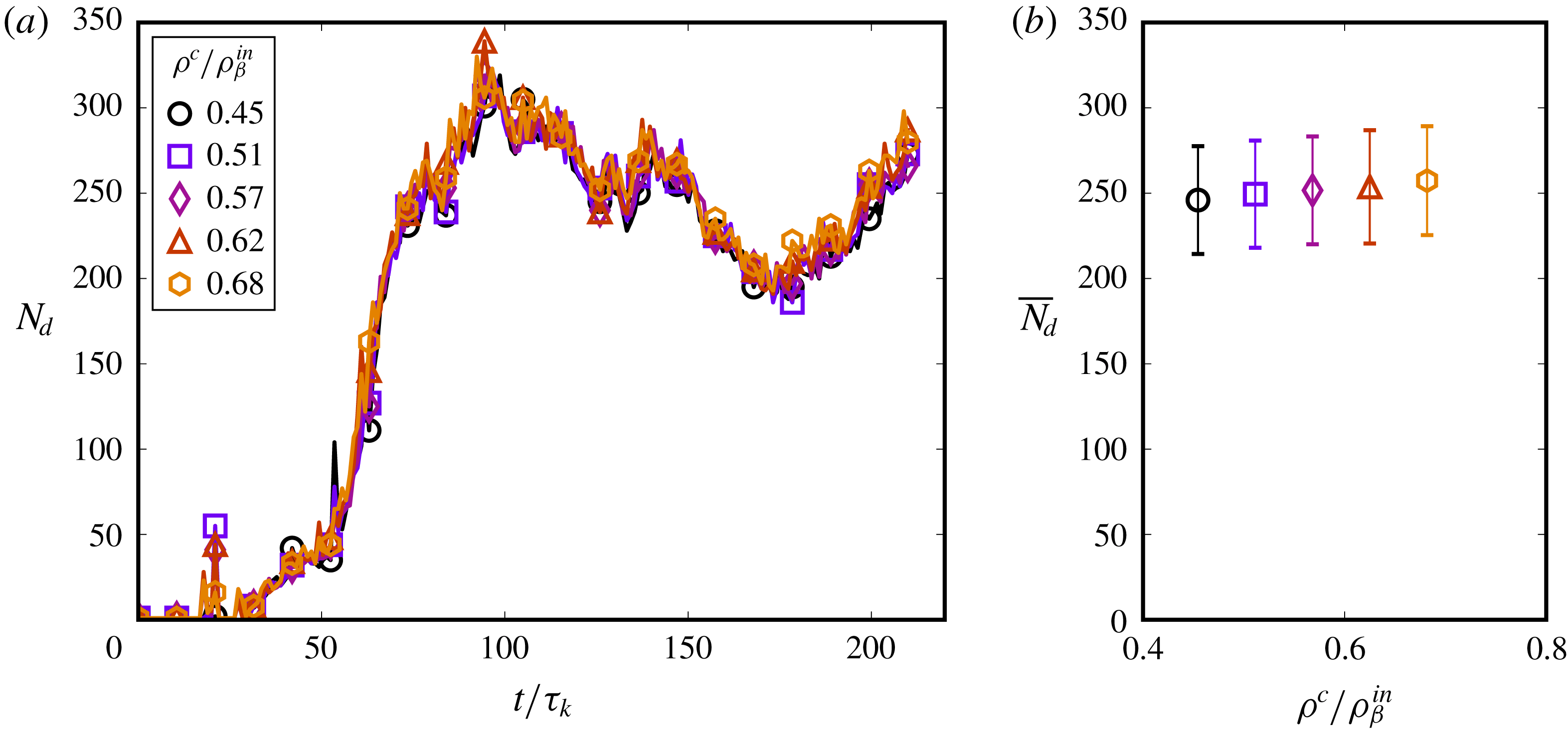
Figure 31. Evolution of droplet number density
 $N_{d}$
for varying
$N_{d}$
for varying
 $\unicode[STIX]{x1D70C}^{c}$
shows that the number of droplets identified is almost independent of
$\unicode[STIX]{x1D70C}^{c}$
shows that the number of droplets identified is almost independent of
 $\unicode[STIX]{x1D70C}^{c}$
.
$\unicode[STIX]{x1D70C}^{c}$
.


 Open access