1. Introduction
Ice sheets flow as viscous gravity currents covering hundreds to thousands of kilometres over centuries to millennia. Supplied by snowfall, ice sheets can terminate on land (terrestrial ice sheets), once net melting and sublimation (the change of phase from solid to vapour) balance the flow rate, or in the ocean (marine ice sheets) by calving (splitting off) icebergs. Often, marine ice sheets flowing over bedrock that is below sea level feed floating ice shelves across a grounding line where the conditions necessary for flotation are first met and the ice sheet detaches from the bedrock. General descriptions of ice sheets, beautifully illustrated, can be found in Hambrey & Alean (Reference Hambrey and Alean2004). A schematic diagram illustrating the idealised geometry of a marine ice sheet that forms the basis of our theoretical and experimental modelling is shown in figure 1.
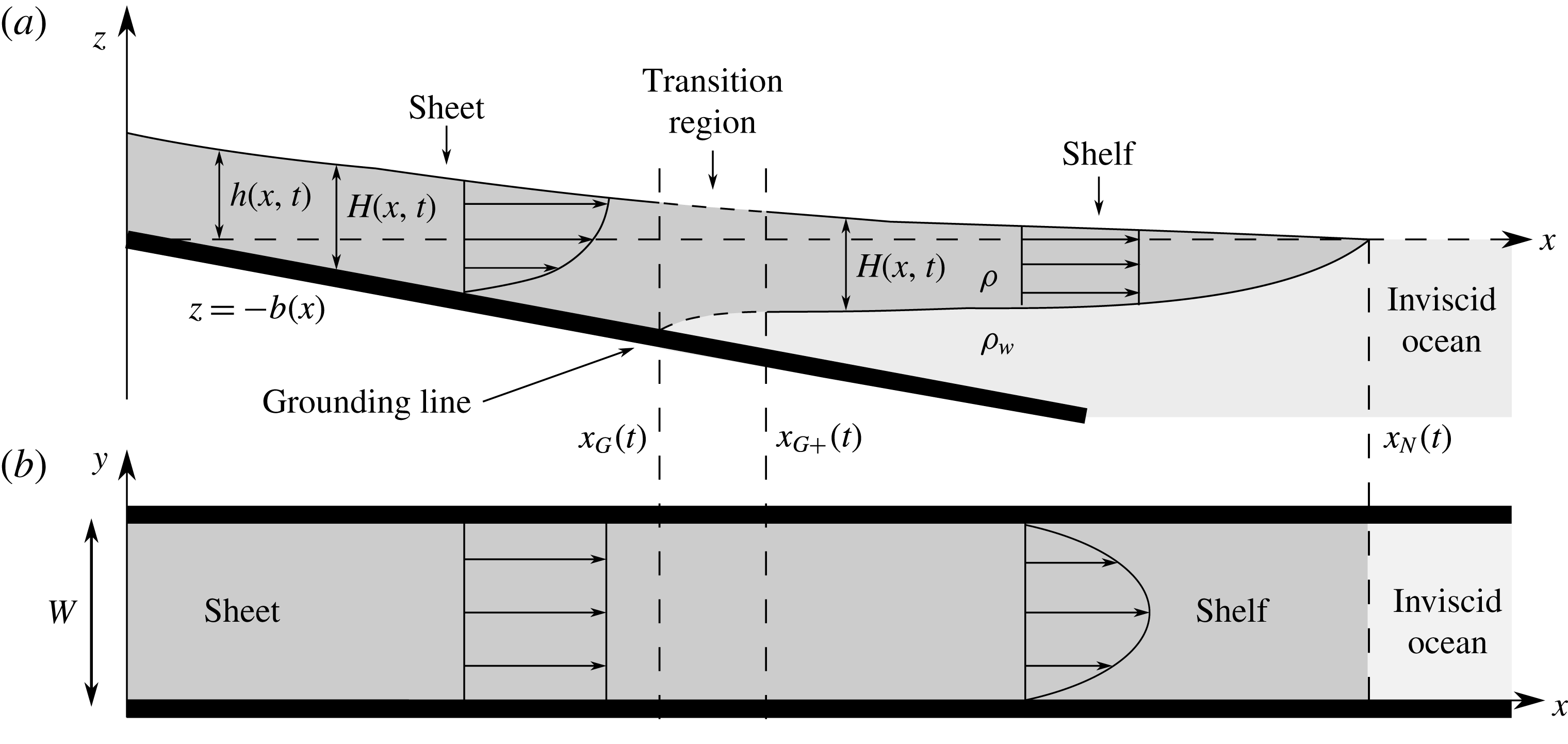
Figure 1. Schematic diagram illustrating (a) the side profile and (b) the plan view of a viscous fluid layer confined between two parallel sidewalls and intruding into an inviscid ocean.
Ice is a polycrystalline material that flows by grain-boundary creep and regelation (melting and refreezing of ice grains). On large length and time scales, ice behaves as a shear-thinning viscous fluid, usually with a simple power-law rheology described by Glen’s flow law (Glen Reference Glen1955). However, much of the fundamental fluid mechanics that governs the mass and force balances across a grounding line can be understood using Newtonian fluid mechanics, which we focus on here so that the governing dynamical principles can be tested straightforwardly in the laboratory using simple fluids.
Many previous theoretical studies of grounding-line dynamics have considered two-dimensional idealisations, in which it is readily shown that the floating shelf has no dynamical influence on the grounding line nor on the rate of flow of the ice sheet upstream of it (Weertman Reference Weertman1974; Wilchinsky & Chugunov Reference Wilchinsky and Chugunov2000; Schoof Reference Schoof2007; Robison, Huppert & Worster Reference Robison, Huppert and Worster2010). Yet it is known from events such as the collapse of the Larsen B ice shelf in 2002 that ice sheets accelerate once the ice shelves they feed are removed. In other words, ice shelves play an important role in buttressing ice sheets, potentially stabilising the grounding lines against retreat (Dupont & Alley Reference Dupont and Alley2005; Gudmundsson Reference Gudmundsson2013).
Robison et al. (Reference Robison, Huppert and Worster2010) presented the first fluid-mechanical laboratory experiment designed to explore fundamental dynamics of marine ice sheets and their grounding lines, using a very viscous fluid (golden syrup) flowing into a denser and effectively inviscid fluid (aqueous potassium carbonate) to simulate the flow of ice into the ocean. They also presented a two-dimensional model that predicts an ultimate steady position for the grounding line. Their experiments cannot be considered two-dimensional because the floating shelf was strongly influenced by the sidewalls of the experimental tank. Their experiments were also influenced by the fact that the ‘sea level’ rose as the syrup intruded into it, which was not included in the theoretical predictions that were compared directly with the experimental data. The position of the grounding line in their experiments advanced initially but retreated ultimately, and it was the maximum extent of the grounding line that was compared against the predicted steady position. Nevertheless, the parametric trends between the theoretical steady position and the measured maximum extent were shown to be similar. Robison et al. (Reference Robison, Huppert and Worster2010) augmented their model with an ad hoc additional resistive force applied to the shelf to illustrate that such resistance causes the grounding line to advance.
Pegler & Worster (Reference Pegler and Worster2013) presented a combined experimental and theoretical study of axisymmetric sheet–shelf systems to show how horizontal stresses in the shelf can act to buttress the grounded sheet. The most robust experimental and theoretical study of a buttressed sheet–shelf system was provided by Pegler et al. (Reference Pegler, Kowal, Hasenclever and Worster2013), who studied the case of flow in a vertical Hele-Shaw cell such that the width
![]() $W$
, depth
$W$
, depth
![]() $H$
and length
$H$
and length
![]() $L$
satisfied
$L$
satisfied
![]() $W\ll H\ll L$
. This is perhaps the simplest limit to consider dynamically because the horizontal forces exerted across the grounding line are given simply by the hydrostatic pressures in the sheet and shelf on either side. Indeed, excellent agreement was found between the theoretical predictions and the experimental data. However, in more general situations, longitudinal extensional stresses in the shelf can be important and the force balance is more involved.
$W\ll H\ll L$
. This is perhaps the simplest limit to consider dynamically because the horizontal forces exerted across the grounding line are given simply by the hydrostatic pressures in the sheet and shelf on either side. Indeed, excellent agreement was found between the theoretical predictions and the experimental data. However, in more general situations, longitudinal extensional stresses in the shelf can be important and the force balance is more involved.
In this paper, we study a more realistic limit in which
![]() $H\ll W\ll L$
. This is typical of many confined marine ice sheets in nature, in which the floating shelf flows through a long, narrow fjord that is nonetheless wider than the thickness of ice. The Amery Ice Shelf, for example, is several hundred metres thick (ranging from approximately 2 km at the grounding line to 300 m at the calving front, the leading edge of the ice shelf), 50 km wide at the upstream end diverging to approximately 200 km at the calving front and is approximately 550 km long, confined by stationary ice on either side. We present a new set of experiments performed in the same configuration as that studied by Robison et al. (Reference Robison, Huppert and Worster2010), though controlling ‘sea level’ carefully to keep it constant, and a new theory (Pegler Reference Pegler2012) that couples a grounded sheet dominated by vertical shear stresses to a floating shelf dominated by horizontal shear stresses. Pegler (Reference Pegler2012) showed that extensional stresses are negligible except within a short transition zone of the shelf downstream of the grounding line and that the transition zone can be integrated across in the flow direction to give jump conditions between the shear-dominated regions.
$H\ll W\ll L$
. This is typical of many confined marine ice sheets in nature, in which the floating shelf flows through a long, narrow fjord that is nonetheless wider than the thickness of ice. The Amery Ice Shelf, for example, is several hundred metres thick (ranging from approximately 2 km at the grounding line to 300 m at the calving front, the leading edge of the ice shelf), 50 km wide at the upstream end diverging to approximately 200 km at the calving front and is approximately 550 km long, confined by stationary ice on either side. We present a new set of experiments performed in the same configuration as that studied by Robison et al. (Reference Robison, Huppert and Worster2010), though controlling ‘sea level’ carefully to keep it constant, and a new theory (Pegler Reference Pegler2012) that couples a grounded sheet dominated by vertical shear stresses to a floating shelf dominated by horizontal shear stresses. Pegler (Reference Pegler2012) showed that extensional stresses are negligible except within a short transition zone of the shelf downstream of the grounding line and that the transition zone can be integrated across in the flow direction to give jump conditions between the shear-dominated regions.
In § 2 we develop our theoretical model, focusing particularly on the new matching conditions across the grounding and transition zones. Some numerical integrations of the model are presented for flow from a localised source of constant flux providing viscous fluid along a sloping, rigid base, thence into a denser, inviscid fluid region. These are complemented and compared with similarity solutions valid at long times after the initiation of the flow in § 3. Our laboratory experiments are reported in § 4, where the measurements are compared with the numerical solutions of our theoretical model. Very good agreement is found for the shape of the shelf and the positions of the grounding line and shelf front.
2. Theoretical model and results
Consider fluid of dynamic viscosity
![]() ${\it\mu}$
and density
${\it\mu}$
and density
![]() ${\it\rho}$
flowing down a rigid slope
${\it\rho}$
flowing down a rigid slope
![]() $z=-b(x)=-{\it\alpha}x$
, where
$z=-b(x)=-{\it\alpha}x$
, where
![]() ${\it\alpha}$
${\it\alpha}$
![]() ${>}0$
is constant, into a dense inviscid ‘ocean’ of density
${>}0$
is constant, into a dense inviscid ‘ocean’ of density
![]() ${\it\rho}_{w}>{\it\rho}$
(figure 1
a). The whole system is confined between parallel, vertical walls a distance
${\it\rho}_{w}>{\it\rho}$
(figure 1
a). The whole system is confined between parallel, vertical walls a distance
![]() $W$
apart (figure 1
b). The viscous fluid is supplied at constant flux per unit width
$W$
apart (figure 1
b). The viscous fluid is supplied at constant flux per unit width
![]() $q_{0}$
at
$q_{0}$
at
![]() $x=0$
, forms a gravity current (sheet) for
$x=0$
, forms a gravity current (sheet) for
![]() $0<x<x_{G}(t)$
, and begins to float at the grounding line
$0<x<x_{G}(t)$
, and begins to float at the grounding line
![]() $x=x_{G}(t)$
to form a floating current (shelf) for
$x=x_{G}(t)$
to form a floating current (shelf) for
![]() $x_{G}(t)<x<x_{N}(t)$
.
$x_{G}(t)<x<x_{N}(t)$
.
Following Pegler (Reference Pegler2012) we consider the flow in three regions: the region
![]() $0<x<x_{G}$
, in which the viscous current is grounded and is dominated by vertical shear stresses (the sidewalls have negligible influence); the region
$0<x<x_{G}$
, in which the viscous current is grounded and is dominated by vertical shear stresses (the sidewalls have negligible influence); the region
![]() $x_{G+}<x<x_{N}$
, in which the viscous current is floating and dominated by transverse, horizontal shear stresses originating from the condition of no slip at the confining sidewalls; and the transition region
$x_{G+}<x<x_{N}$
, in which the viscous current is floating and dominated by transverse, horizontal shear stresses originating from the condition of no slip at the confining sidewalls; and the transition region
![]() $x_{G}<x<x_{G+}$
linking the two former regions.
$x_{G}<x<x_{G+}$
linking the two former regions.
In the grounded region
![]() $0<x<x_{G}$
, the viscous fluid forms a classical viscous gravity current with surface elevation above sea level
$0<x<x_{G}$
, the viscous fluid forms a classical viscous gravity current with surface elevation above sea level
![]() $h(x,t)$
and thickness
$h(x,t)$
and thickness
![]() $H(x,t)=h(x,t)+b(x)$
. When
$H(x,t)=h(x,t)+b(x)$
. When
![]() $H\ll W$
the flow is essentially two-dimensional (independent of
$H\ll W$
the flow is essentially two-dimensional (independent of
![]() $y$
) with horizontal velocity
$y$
) with horizontal velocity
satisfying no-slip at
![]() $z=-b(x)$
and no-stress at
$z=-b(x)$
and no-stress at
![]() $z=h(x,t)$
, where
$z=h(x,t)$
, where
![]() $y$
is the horizontal cross-stream coordinate and
$y$
is the horizontal cross-stream coordinate and
![]() $z$
is the vertical coordinate. This flow has flux per unit width
$z$
is the vertical coordinate. This flow has flux per unit width
where
![]() ${\it\nu}$
is its kinematic viscosity, and
${\it\nu}$
is its kinematic viscosity, and
![]() $g$
is the acceleration due to gravity (Robison et al.
Reference Robison, Huppert and Worster2010, cf. Huppert Reference Huppert1982).
$g$
is the acceleration due to gravity (Robison et al.
Reference Robison, Huppert and Worster2010, cf. Huppert Reference Huppert1982).
The flow in the region
![]() $x_{G+}<x<x_{N}$
is simplified by making three approximations as follows. We assume first that there are no bending stresses in the shelf so that it satisfies the flotation condition
$x_{G+}<x<x_{N}$
is simplified by making three approximations as follows. We assume first that there are no bending stresses in the shelf so that it satisfies the flotation condition
![]() ${\it\rho}H={\it\rho}_{w}(H-h)$
. The upper surface elevation is therefore given by
${\it\rho}H={\it\rho}_{w}(H-h)$
. The upper surface elevation is therefore given by
![]() $h(x,t)=(g^{\prime }/g)H(x,t)$
, where
$h(x,t)=(g^{\prime }/g)H(x,t)$
, where
![]() $g^{\prime }=g({\it\rho}_{w}-{\it\rho})/{\it\rho}_{w}$
is a reduced gravity. Secondly, we assume that the air above the shelf and the water (solution) beneath it exert negligible stress on the shelf, so that the horizontal velocity in the shelf is vertically uniform (independent of
$g^{\prime }=g({\it\rho}_{w}-{\it\rho})/{\it\rho}_{w}$
is a reduced gravity. Secondly, we assume that the air above the shelf and the water (solution) beneath it exert negligible stress on the shelf, so that the horizontal velocity in the shelf is vertically uniform (independent of
![]() $z$
) to leading order. Finally, we assume that lateral and longitudinal length scales are characterised by
$z$
) to leading order. Finally, we assume that lateral and longitudinal length scales are characterised by
![]() $W$
and
$W$
and
![]() $L$
in this region so that, when
$L$
in this region so that, when
![]() $W\ll L$
, this region acts like a Hele-Shaw cell with a parabolic flow profile
$W\ll L$
, this region acts like a Hele-Shaw cell with a parabolic flow profile
satisfying no-slip at the sidewalls
![]() $y=0,W$
. This flow has a volume flux per unit width
$y=0,W$
. This flow has a volume flux per unit width
(Pegler et al. Reference Pegler, Kowal, Hasenclever and Worster2013).
Expressions (2.2) and (2.4) for the two-dimensional volume fluxes can be incorporated into the mass conservation equation
to determine a partial differential equation for
![]() $H(x,t)$
in each region. This system of equations is of fourth order in
$H(x,t)$
in each region. This system of equations is of fourth order in
![]() $x$
and has free boundaries at
$x$
and has free boundaries at
![]() $x=x_{G}(t)$
,
$x=x_{G}(t)$
,
![]() $x=x_{G+}(t)$
and
$x=x_{G+}(t)$
and
![]() $x=x_{N}(t)$
, so seven spatial boundary conditions are needed to close the system. The equation in the grounded region is subject to boundary conditions representing the input flux
$x=x_{N}(t)$
, so seven spatial boundary conditions are needed to close the system. The equation in the grounded region is subject to boundary conditions representing the input flux
![]() $q(0,t)=q_{0}$
and the fact that the grounding line is the first place where the flotation condition is met, so
$q(0,t)=q_{0}$
and the fact that the grounding line is the first place where the flotation condition is met, so
![]() $H(x_{G},t)(1-g^{\prime }/g)={\it\alpha}x_{G}(t)$
. The equation in the floating region is subject to
$H(x_{G},t)(1-g^{\prime }/g)={\it\alpha}x_{G}(t)$
. The equation in the floating region is subject to
![]() $H(x_{N},t)=0$
and a kinematic evolution equation for the position of the leading edge
$H(x_{N},t)=0$
and a kinematic evolution equation for the position of the leading edge
where the
![]() $x$
subscript denotes
$x$
subscript denotes
![]() $\partial /\partial x$
and the dot denotes differentiation with respect to time. In addition, there are two conditions derived from a force balance and from mass continuity, as described below, and considerations of the transition region between
$\partial /\partial x$
and the dot denotes differentiation with respect to time. In addition, there are two conditions derived from a force balance and from mass continuity, as described below, and considerations of the transition region between
![]() $x_{G}$
and
$x_{G}$
and
![]() $x_{G+}$
that close the system. Initially, the fluid emerges from a point singularity at
$x_{G+}$
that close the system. Initially, the fluid emerges from a point singularity at
![]() $x=0$
with
$x=0$
with
![]() $x_{G}=x_{N}=0$
and
$x_{G}=x_{N}=0$
and
![]() $H=0$
.
$H=0$
.
2.1. Evolution of the grounding line
The net horizontal force per unit width in the shelf can be written as
where the first term on the right-hand side is the hydrostatic pressure force exerted by the ocean, transmitted through the shelf to the grounding line, and
![]() $B(t)$
is the buttressing force per unit width resulting from shear stresses exerted all along the confining sidewalls of the shelf, given by
$B(t)$
is the buttressing force per unit width resulting from shear stresses exerted all along the confining sidewalls of the shelf, given by
Close to the grounding line, within the transition region indicated by dashed curves in figure 1 the velocity field can be influenced by all components of the stress. However, once the shelf is much longer than the transition region,
![]() $L\gg x_{G+}-x_{G}$
, we can approximate the buttressing force per unit width by
$L\gg x_{G+}-x_{G}$
, we can approximate the buttressing force per unit width by
neglecting the shear stresses in the relatively short transition region and using the expression for
![]() $u$
given by (2.3).
$u$
given by (2.3).
The net longitudinal force in the sheet per unit width can be calculated to be
from the expression for the velocity field given by (2.1) (Robison et al. Reference Robison, Huppert and Worster2010). The first term on the right-hand side is the hydrostatic pressure force and the second term is the viscous contribution to the net horizontal force in the sheet.
We proceed by identifying
![]() $x_{G+}$
with
$x_{G+}$
with
![]() $x_{G}$
and replacing the transition region with a singular interface
$x_{G}$
and replacing the transition region with a singular interface
![]() $x=x_{G}$
separating the sheet from the shelf. In consequence, the dependent variables
$x=x_{G}$
separating the sheet from the shelf. In consequence, the dependent variables
![]() $H$
,
$H$
,
![]() $N$
and
$N$
and
![]() $q$
can in principle be discontinuous across
$q$
can in principle be discontinuous across
![]() $x=x_{G}$
, though the arguments above indicate that
$x=x_{G}$
, though the arguments above indicate that
![]() $N$
itself is continuous within the approximation of our model.
$N$
itself is continuous within the approximation of our model.
We therefore equate expression (2.7) with
![]() $B=B_{+}$
to expression (2.10) to determine the gradient of volume flux in the sheet
$B=B_{+}$
to expression (2.10) to determine the gradient of volume flux in the sheet
where the subscript
![]() $_{+}$
denotes quantities to be evaluated at the upstream boundary of the shelf
$_{+}$
denotes quantities to be evaluated at the upstream boundary of the shelf
![]() $x=x_{G+}$
, while unsubscripted variables are to be evaluated at the downstream boundary of the sheet
$x=x_{G+}$
, while unsubscripted variables are to be evaluated at the downstream boundary of the sheet
![]() $x=x_{G}$
. Since
$x=x_{G}$
. Since
![]() $x_{G+}$
has been identified with
$x_{G+}$
has been identified with
![]() $x_{G}$
,
$x_{G}$
,
![]() $H_{+}$
and
$H_{+}$
and
![]() $H$
here represent the right-hand and left-hand values of
$H$
here represent the right-hand and left-hand values of
![]() $H$
either side of the discontinuity.
$H$
either side of the discontinuity.
Since the flotation condition
![]() ${\it\rho}H(x_{G}(t),t)={\it\rho}_{w}b(x_{G}(t))$
applies at the grounding line for all time, we can differentiate it with respect to time to give
${\it\rho}H(x_{G}(t),t)={\it\rho}_{w}b(x_{G}(t))$
applies at the grounding line for all time, we can differentiate it with respect to time to give
which can be rewritten as
by using the continuity equation (2.5). From this and using the expression for the flux gradient from (2.11), we obtain an equation describing the evolution of the grounding line:
 $$\begin{eqnarray}{\dot{x}}_{G}^{\mathit{dyn}}=\frac{\displaystyle \frac{g}{2{\it\nu}}\left(H\frac{\partial h}{\partial x}\right)^{2}-\frac{g^{\prime }}{8{\it\nu}}(H^{2}-H_{+}^{2})}{\displaystyle -\frac{\partial H}{\partial x}+\frac{{\it\rho}_{w}}{{\it\rho}}\frac{\partial b}{\partial x}}.\end{eqnarray}$$
This is similar to the expression derived in Robison et al. (Reference Robison, Huppert and Worster2010) but with the addition of the buttressing term proportional to
![]() $H_{+}^{2}$
(Pegler Reference Pegler2012). Note that both terms in the denominator of (2.14) are positive, so it is clear that buttressing causes the grounding line to advance.
$H_{+}^{2}$
(Pegler Reference Pegler2012). Note that both terms in the denominator of (2.14) are positive, so it is clear that buttressing causes the grounding line to advance.
It was noted by Robison et al. (Reference Robison, Huppert and Worster2010) that when the grounded sheet terminates in shallow water the hydrostatic pressure from the ocean is insufficient to balance the longitudinal forces in the ice sheet. In that case, no ice shelf forms and the terminus of the ice sheet advances kinematically according to
The same considerations apply here, so the evolution equation for the grounding line applied in our model is therefore
The final boundary condition required to close the system comes from conservation of mass across the moving grounding line, which is expressed by
Note that both
![]() $H$
and
$H$
and
![]() $q$
can be discontinuous across the singular grounding line in this model, which represents the changes in thickness and flux across the transition region.
$q$
can be discontinuous across the singular grounding line in this model, which represents the changes in thickness and flux across the transition region.
2.2. Non-dimensionalisation
We non-dimensionalise the governing equations by the intrinsic length, time and thickness scales associated with the flow of the grounded sheet and write
(Robison et al. Reference Robison, Huppert and Worster2010). After dropping hats, the dimensionless equations describing mass conservation in the sheet and the shelf, derived from (2.5) using (2.2) and (2.4), are
The equation in the sheet is subject to the constant flux provided at the origin and the flotation condition at the grounding line
while conservation of mass across the grounding line (2.17) becomes
The front of the shelf of zero thickness advances kinematically as in (2.6) according to
while the grounding line advances according to (2.16)
where
 $$\begin{eqnarray}\displaystyle {\dot{x}}_{G}^{\mathit{dyn}}=\frac{\displaystyle \frac{1}{2}\left(H\frac{\partial h}{\partial x}\right)^{2}-\frac{1}{8}(H^{2}-H_{+}^{2})}{\displaystyle -\frac{\partial H}{\partial x}+\tilde{\mathscr{A}}}\quad {\dot{x}}_{G}^{\mathit{kin}}=-\frac{1}{3}H^{2}\frac{\partial h}{\partial x}\quad (x=x_{G}). & & \displaystyle\end{eqnarray}$$
Three dimensionless parameters appear, namely
which represent the dimensionless width of the channel, the dimensionless density ratio or ratio of reduced gravity to gravity and the dimensionless bed slope respectively. For clarity, we have also introduced
![]() $\tilde{\mathscr{A}}=\mathscr{A}/(1-{\it\epsilon})$
.
$\tilde{\mathscr{A}}=\mathscr{A}/(1-{\it\epsilon})$
.

Figure 2. Numerical solution of (2.19)–(2.25) for the side profile of the sheet–shelf system for a sequence of values of
![]() $t=1,2,\ldots ,6$
. Here,
$t=1,2,\ldots ,6$
. Here,
![]() $\mathscr{W}=1,{\it\epsilon}=0.1,\mathscr{A}=1$
. The transition region between
$\mathscr{W}=1,{\it\epsilon}=0.1,\mathscr{A}=1$
. The transition region between
![]() $x_{G}$
and
$x_{G}$
and
![]() $x_{G+}$
has been modelled as a singular interface across which the thickness of the current is discontinuous, as shown by the dashed vertical lines.
$x_{G+}$
has been modelled as a singular interface across which the thickness of the current is discontinuous, as shown by the dashed vertical lines.
We solved (2.19)–(2.25) using a second-order, finite-difference scheme after mapping the domains of the sheet and shelf to fixed unit intervals (cf. Acton et al. Reference Acton, Huppert and Worster2001). To initialise our computations, we used the asymptotic solution for the early-time evolution of the two-dimensional sheet derived in Robison et al. (Reference Robison, Huppert and Worster2010).
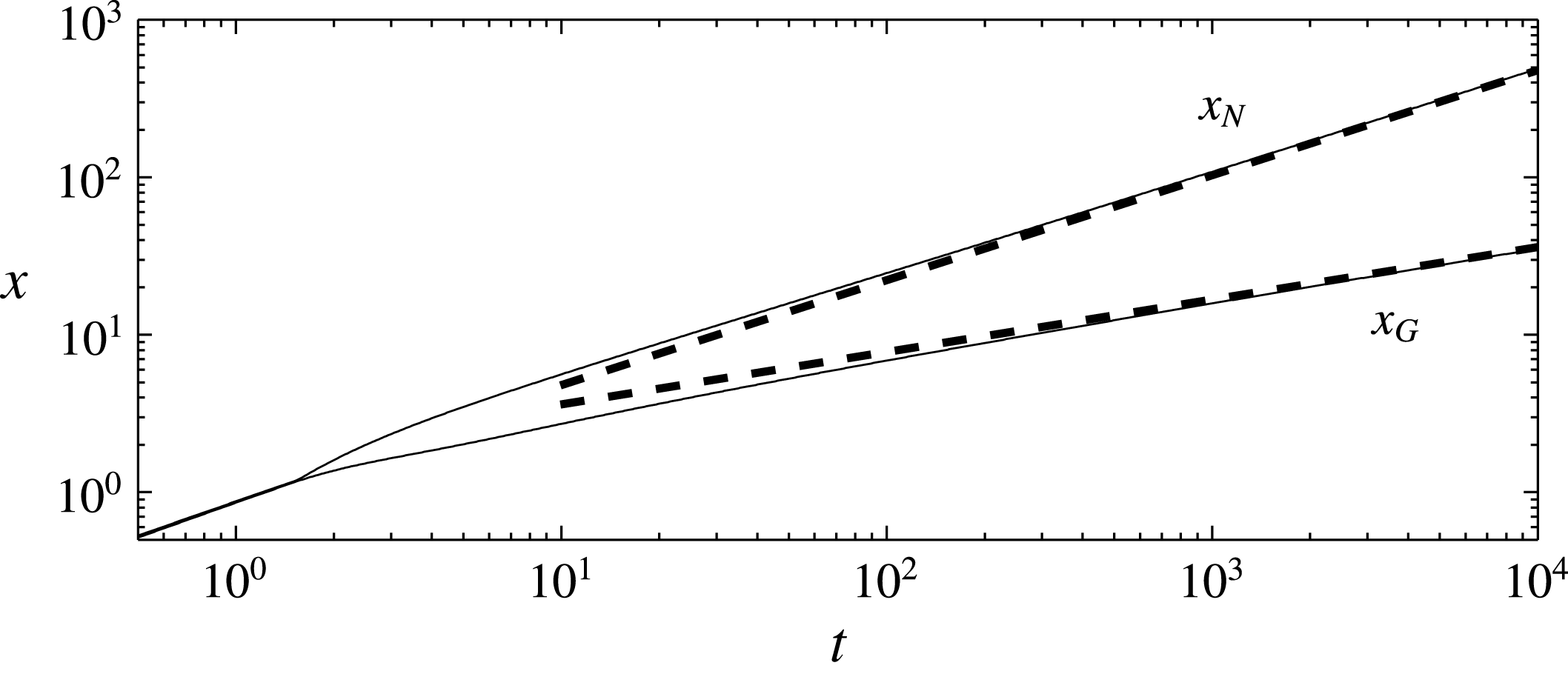
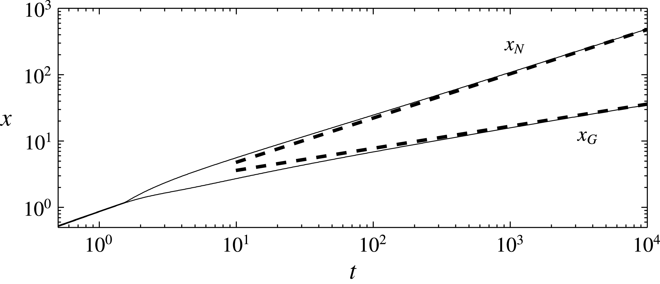
Representative solutions for the profile thicknesses are shown in figure 2 while the evolutions of the grounding line and leading edge are shown in figure 3 using illustrative parameter values
![]() $\mathscr{W}=1,{\it\epsilon}=0.1,\mathscr{A}=1$
. Parameter values representative of marine ice sheets are approximately
$\mathscr{W}=1,{\it\epsilon}=0.1,\mathscr{A}=1$
. Parameter values representative of marine ice sheets are approximately
![]() $\mathscr{W}=1{-}100,{\it\epsilon}=0.1,\mathscr{A}=10^{-4}{-}10^{-3}$
. The range of values estimated here for
$\mathscr{W}=1{-}100,{\it\epsilon}=0.1,\mathscr{A}=10^{-4}{-}10^{-3}$
. The range of values estimated here for
![]() $\mathscr{W}$
should be treated cautiously given that ice sheets are non-Newtonian, with variable effective viscosity, so a range of typical viscosities in the region of
$\mathscr{W}$
should be treated cautiously given that ice sheets are non-Newtonian, with variable effective viscosity, so a range of typical viscosities in the region of
![]() $5\times 10^{12}{-}10^{15}$
Pa s was used. Figure 2 is representative of three stages. Initially, there is no shelf and the grounding line evolves kinematically. Once the grounding line evolves dynamically and a shelf forms, at about
$5\times 10^{12}{-}10^{15}$
Pa s was used. Figure 2 is representative of three stages. Initially, there is no shelf and the grounding line evolves kinematically. Once the grounding line evolves dynamically and a shelf forms, at about
![]() $t=1.5$
, there is a discontinuity in thickness across the singular transition region. At large times, the discontinuity in thickness diminishes. Our experiments, described in § 4 ran to dimensionless times of order
$t=1.5$
, there is a discontinuity in thickness across the singular transition region. At large times, the discontinuity in thickness diminishes. Our experiments, described in § 4 ran to dimensionless times of order
![]() $10^{2}$
and are therefore mostly representative of the third, large-time regime.
$10^{2}$
and are therefore mostly representative of the third, large-time regime.
3. Asymptotic results
At late times, the shelf is much longer than the sheet and the numerical solutions indicate that most of the source flux is transmitted through the sheet to the shelf more than advancing the grounding line, with
![]() $q\approx 1$
throughout the sheet. The shelf then evolves self-similarly, as if supplied by a constant dimensionless flux
$q\approx 1$
throughout the sheet. The shelf then evolves self-similarly, as if supplied by a constant dimensionless flux
![]() $q=1$
near the origin, with the same scaling as found in related studies by Huppert & Woods (Reference Huppert and Woods1995) and Pegler et al. (Reference Pegler, Kowal, Hasenclever and Worster2013), namely
$q=1$
near the origin, with the same scaling as found in related studies by Huppert & Woods (Reference Huppert and Woods1995) and Pegler et al. (Reference Pegler, Kowal, Hasenclever and Worster2013), namely
where
![]() ${\it\eta}=x/x_{N}$
. The dimensionless function
${\it\eta}=x/x_{N}$
. The dimensionless function
![]() $f({\it\eta})$
satisfies the ordinary differential equation
$f({\it\eta})$
satisfies the ordinary differential equation
with boundary conditions
from which
![]() ${\it\eta}_{N}$
is determined to be
${\it\eta}_{N}$
is determined to be
![]() ${\it\eta}_{N}\approx 1.03$
. The differential equation originates from (2.18). The second and third boundary conditions originate from (2.21a
) and (2.21b
) respectively, while the first describes the imposed constant flux at the entry to the shelf.
${\it\eta}_{N}\approx 1.03$
. The differential equation originates from (2.18). The second and third boundary conditions originate from (2.21a
) and (2.21b
) respectively, while the first describes the imposed constant flux at the entry to the shelf.
The approach of the full, time-dependent solution towards the asymptotic similarity solution is shown in figures 3 and 4(a).
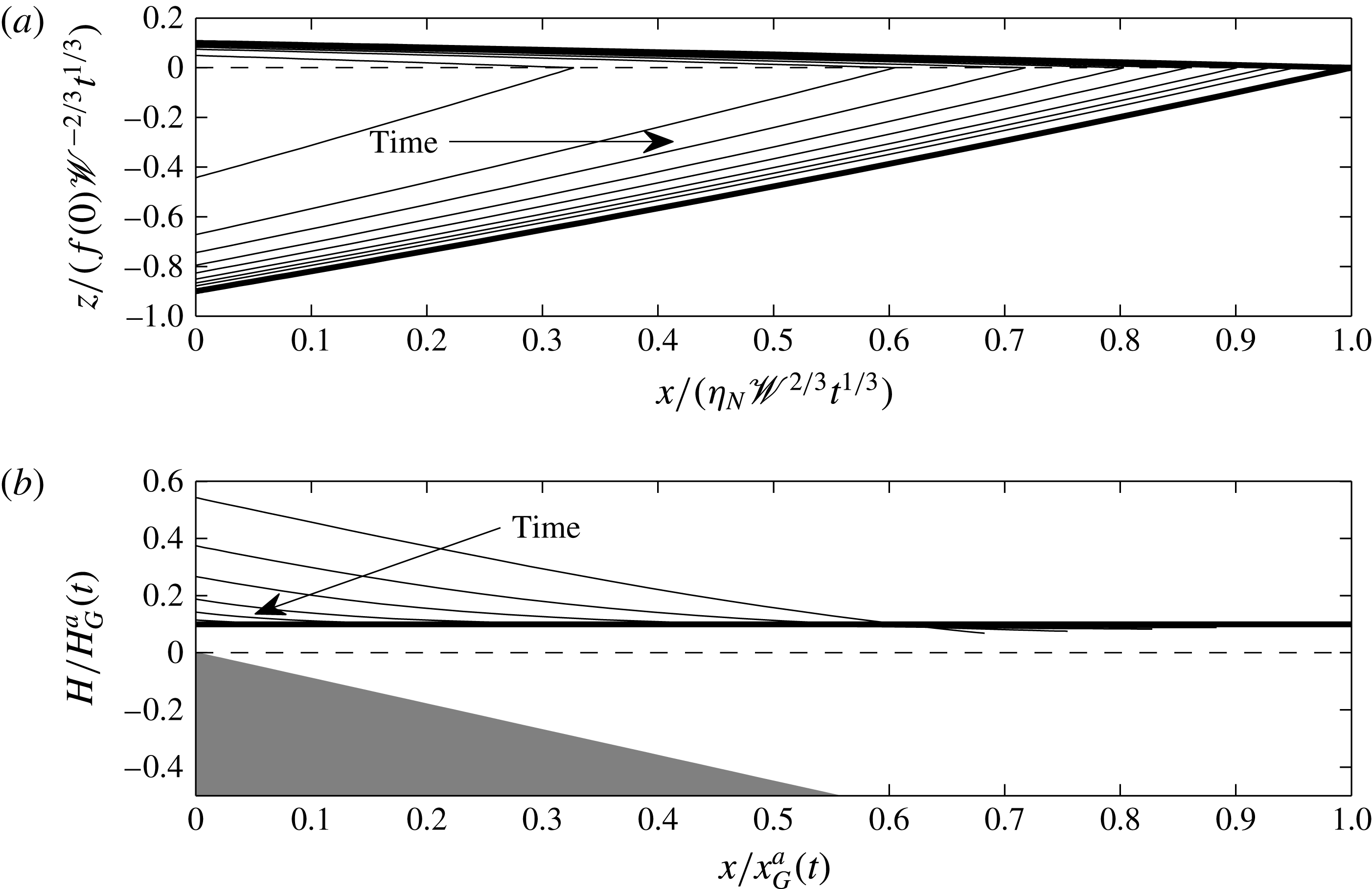
Figure 4. Agreement between asymptotic results and the solution to the full model (2.19)–(2.25) for the shelf and sheet for
![]() $t=3,10,30,100,300,1000,3000,10\,000$
. Note that in panel (b) the curves for
$t=3,10,30,100,300,1000,3000,10\,000$
. Note that in panel (b) the curves for
![]() $t\geqslant 1000$
are indistinguishable from the asymptotic line. (a) The thickness of the shelf (thin curves) presented in similarity coordinates converges to the similarity solution (3.1) (bold curves) as
$t\geqslant 1000$
are indistinguishable from the asymptotic line. (a) The thickness of the shelf (thin curves) presented in similarity coordinates converges to the similarity solution (3.1) (bold curves) as
![]() $t\rightarrow \infty$
. (b) The scaled sheet surface heights
$t\rightarrow \infty$
. (b) The scaled sheet surface heights
![]() $h/H_{G}^{a}$
(thin curves) as functions of scaled distance
$h/H_{G}^{a}$
(thin curves) as functions of scaled distance
![]() $x/x_{G}^{a}$
converge towards the long-time surface height
$x/x_{G}^{a}$
converge towards the long-time surface height
![]() $z=h_{G}(t)$
(bold curve).
$z=h_{G}(t)$
(bold curve).
![]() $H_{G}^{a}(t)$
and
$H_{G}^{a}(t)$
and
![]() $x_{G}^{a}(t)$
are late-time asymptotic predictions for the sheet thickness at the grounding line (3.1a
) and the grounding line position (3.7), respectively. The parameter values used are
$x_{G}^{a}(t)$
are late-time asymptotic predictions for the sheet thickness at the grounding line (3.1a
) and the grounding line position (3.7), respectively. The parameter values used are
![]() $\mathscr{W}=1,{\it\epsilon}=0.1$
and
$\mathscr{W}=1,{\it\epsilon}=0.1$
and
![]() $\mathscr{A}=1$
.
$\mathscr{A}=1$
.
Because most of the source flux is transmitted to the shelf at late times, the sheet reaches a quasi-steady state with uniform flux
At late times, the discontinuity in thickness across the transition region becomes negligible and the ice thickness at the grounding line
from (3.1a
). The sheet, being very long, is mostly in deep water with
![]() $H\gg 1$
. Therefore, from (3.4),
$H\gg 1$
. Therefore, from (3.4),
whence
![]() $h\sim h_{G}(t)={\it\epsilon}H_{G}(t)$
and
$h\sim h_{G}(t)={\it\epsilon}H_{G}(t)$
and
![]() $H\sim h_{G}(t)+\mathscr{A}x.$
Evaluating this last equation at
$H\sim h_{G}(t)+\mathscr{A}x.$
Evaluating this last equation at
![]() $x=x_{G}$
and rearranging, we obtain
$x=x_{G}$
and rearranging, we obtain
with
![]() $f(0)\approx 1.86$
obtained by integrating (3.2). These expressions are shown to give a very good asymptotic fit to the full solution in figures 3 and 4(b) for
$f(0)\approx 1.86$
obtained by integrating (3.2). These expressions are shown to give a very good asymptotic fit to the full solution in figures 3 and 4(b) for
![]() $t\gtrsim 10^{2}$
. Equation (3.5) shows that
$t\gtrsim 10^{2}$
. Equation (3.5) shows that
![]() $\partial H/\partial t\sim t^{-2/3}\ll 1$
as
$\partial H/\partial t\sim t^{-2/3}\ll 1$
as
![]() $t\rightarrow \infty$
, giving validity a posteriori to the quasi-steady approximation for the sheet (3.4). Similarly, our predictions give
$t\rightarrow \infty$
, giving validity a posteriori to the quasi-steady approximation for the sheet (3.4). Similarly, our predictions give
![]() $x_{N}/x_{G}\sim t^{1/3}\gg 1$
as
$x_{N}/x_{G}\sim t^{1/3}\gg 1$
as
![]() $t\rightarrow \infty$
, confirming that the shelf is asymptotically much longer than the sheet. More precisely, this holds when
$t\rightarrow \infty$
, confirming that the shelf is asymptotically much longer than the sheet. More precisely, this holds when
We see from this expression that the asymptotic regime is reached more quickly for larger dimensionless bed slopes
![]() $\mathscr{A}$
or larger dimensionless channel widths
$\mathscr{A}$
or larger dimensionless channel widths
![]() $\mathscr{W}$
.
$\mathscr{W}$
.
4. Experimental results
We performed a series of experiments in an acrylic tank 10 cm wide, 200 cm long and 25 cm deep inclined at an angle
![]() ${\it\theta}$
to the horizontal (figure 5). The bed slope
${\it\theta}$
to the horizontal (figure 5). The bed slope
![]() ${\it\alpha}=\tan {\it\theta}$
. Golden syrup was used for the viscous current, while a more dense aqueous potassium carbonate solution with a viscosity some five orders of magnitude smaller than that of golden syrup was used for the ocean.
${\it\alpha}=\tan {\it\theta}$
. Golden syrup was used for the viscous current, while a more dense aqueous potassium carbonate solution with a viscosity some five orders of magnitude smaller than that of golden syrup was used for the ocean.
Golden syrup was released from a reservoir installed inside the raised end of the tank by lifting a sliding gate into a fixed position. The flux was maintained constant by keeping the reservoir at a constant head. The delivery flux was determined by measuring the total volume of golden syrup supplied to the reservoir during the experiment and dividing by the duration of the experiment. The tank was pre-filled with potassium carbonate solution to within a millimetre below the bottom lip of the sliding gate. During the experiment, the depth of potassium carbonate solution was maintained constant by manual adjustment of a siphon valve at the opposite end of the tank. The side view of each experiment was recorded using a digital camera.
The parameter values used in each experiment are given in table 1. The kinematic viscosities of pure syrup varied from 320 to 460 cm2 s
![]() $^{-1}$
in our experiments depending on the ambient temperature, which varied from experiment to experiment. We additionally lowered the viscosity of syrup to 53 cm2 s
$^{-1}$
in our experiments depending on the ambient temperature, which varied from experiment to experiment. We additionally lowered the viscosity of syrup to 53 cm2 s
![]() $^{-1}$
for one of our experiments, achieved by dilution with approximately 10 % water. We measured the viscosity before each experiment using a falling-sphere method. The density of the golden syrup dilutions ranged from 1.42 to 1.44 g cm
$^{-1}$
for one of our experiments, achieved by dilution with approximately 10 % water. We measured the viscosity before each experiment using a falling-sphere method. The density of the golden syrup dilutions ranged from 1.42 to 1.44 g cm
![]() $^{-3}$
. The densities of potassium carbonate solution ranged from 1.48 to 1.56 g cm
$^{-3}$
. The densities of potassium carbonate solution ranged from 1.48 to 1.56 g cm
![]() $^{-3}$
, leading to values of
$^{-3}$
, leading to values of
![]() ${\it\epsilon}$
ranging from 0.03 to 0.09,
${\it\epsilon}$
ranging from 0.03 to 0.09,
![]() $\mathscr{A}$
ranging from 0.5 to 3, and
$\mathscr{A}$
ranging from 0.5 to 3, and
![]() $\mathscr{W}$
ranging from 1 to 3.
$\mathscr{W}$
ranging from 1 to 3.

Figure 5. Schematic diagram of our experimental set-up. Golden syrup is kept at a constant head in the reservoir and flows under the sliding gate to form a viscous gravity current. The current flows down the sloping base of the tank into a denser solution of potassium carbonate. The level of the solution is kept constant by a siphon.
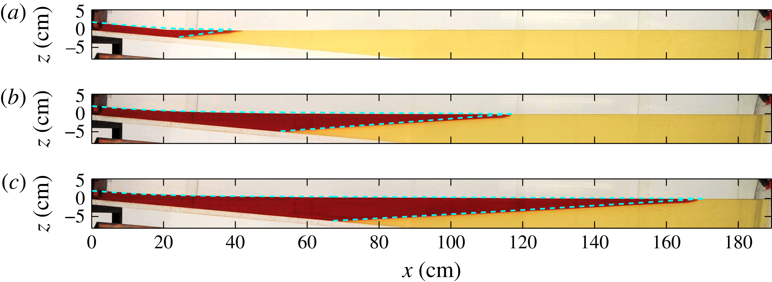
Figure 6. Sequence of photographs of experiment C shown at times
![]() $t=100,500,900$
s with the theoretical prediction for the surface profiles overlain (dashed). The full experiment is shown in supplementary movie 1 available at http://dx.doi.org/10.1017/jfm.2016.37.
$t=100,500,900$
s with the theoretical prediction for the surface profiles overlain (dashed). The full experiment is shown in supplementary movie 1 available at http://dx.doi.org/10.1017/jfm.2016.37.
Table 1. Parameter values used in our experiments.
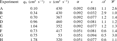
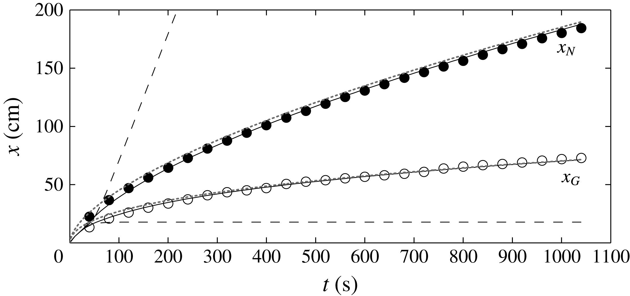
Figure 7. Comparison of experimental data (circles) against numerical solutions (solid curves) of the full model (2.19)–(2.25) for the positions of the grounding line
![]() $x_{G}(t)$
and leading edge
$x_{G}(t)$
and leading edge
![]() $x_{N}(t)$
for experiment C. The positions of the grounding line and leading edge predicted by two-dimensional theory without buttressing (Robison et al.
Reference Robison, Huppert and Worster2010) are shown by the dashed curves. Predictions of the Hele-Shaw model of Pegler et al. (Reference Pegler, Kowal, Hasenclever and Worster2013) are shown by the dotted curves.
$x_{N}(t)$
for experiment C. The positions of the grounding line and leading edge predicted by two-dimensional theory without buttressing (Robison et al.
Reference Robison, Huppert and Worster2010) are shown by the dashed curves. Predictions of the Hele-Shaw model of Pegler et al. (Reference Pegler, Kowal, Hasenclever and Worster2013) are shown by the dotted curves.
A sample sequence of photographs of one of our experiments compared against our theoretical prediction is shown in figure 6, where the experimental shape of the current is seen to agree with our prediction. Both the sheet and the shelf are present in these photographs, and the grounding line evolves dynamically. Note that the dimensionless times in these photographs are all greater than about 20, by which time the discontinuity in thickness across the singular transition region of the theoretical model is less than 1 mm and is not apparent in the overlain solutions.
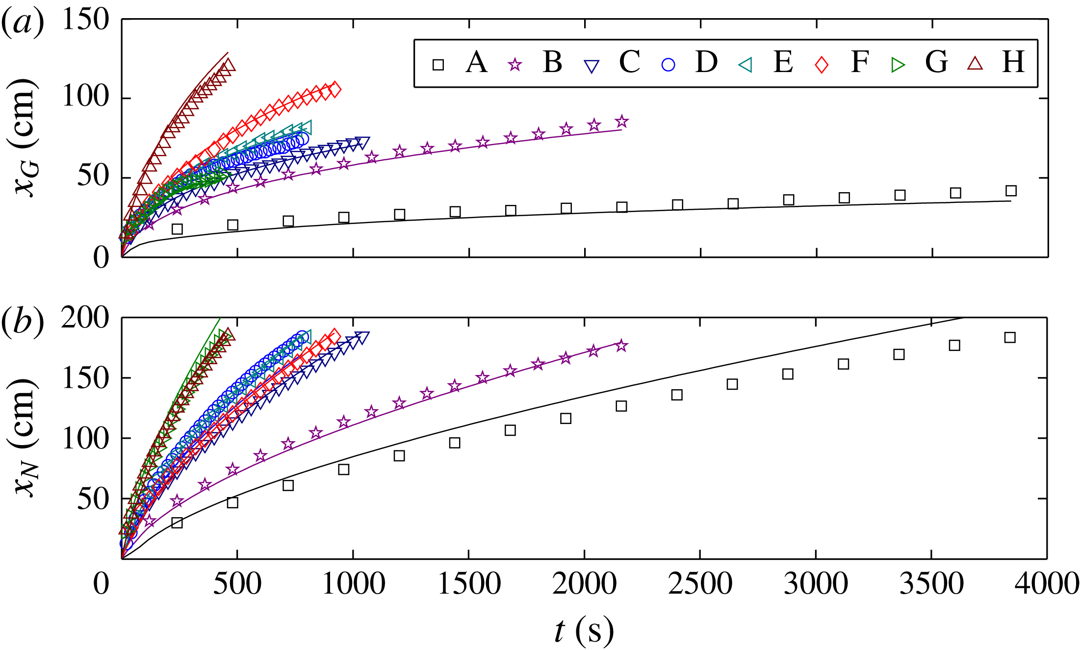
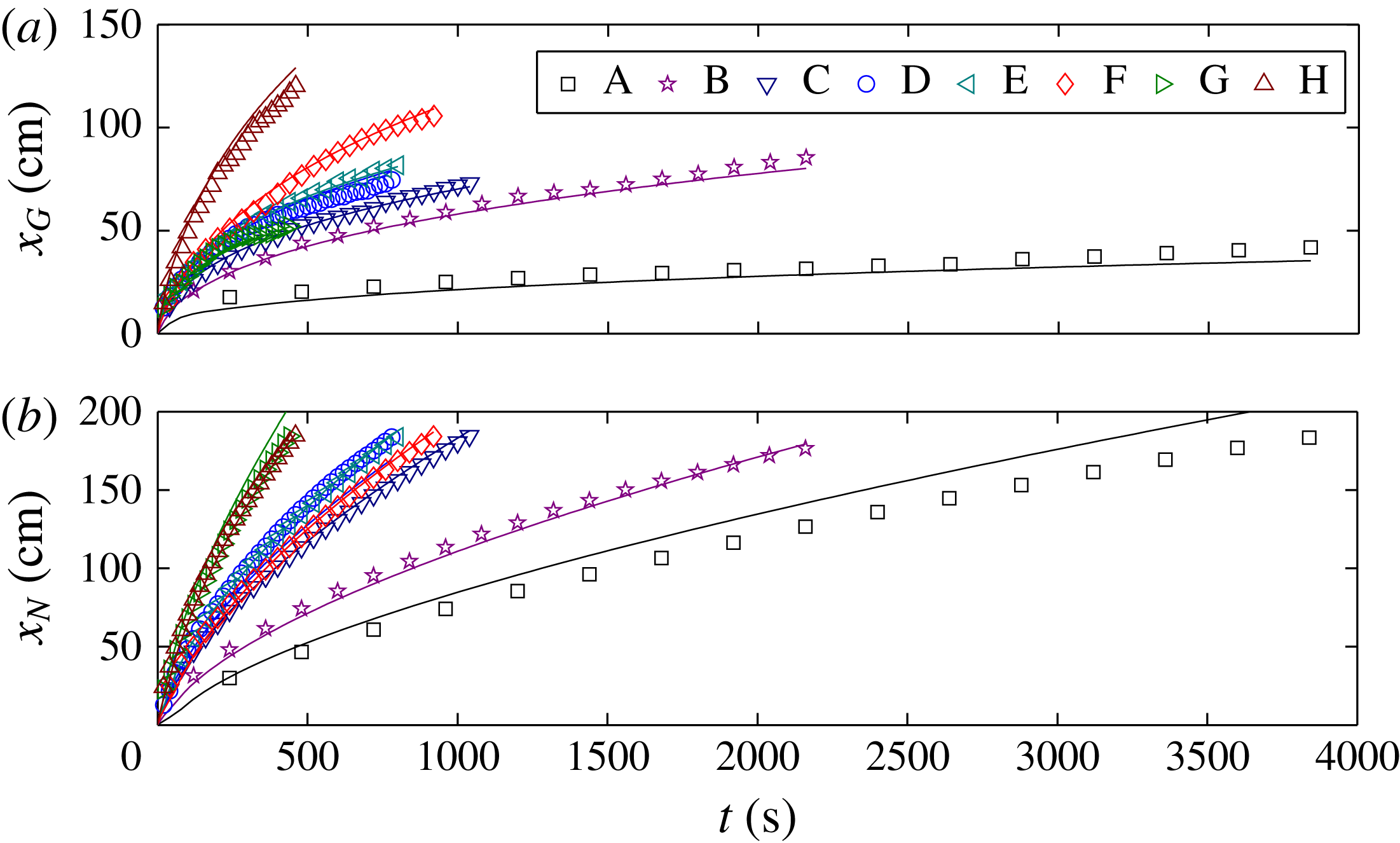
The measured positions of the grounding line and the leading edge (circles) are compared with our theoretical predictions (solid curves) in figure 7 for a representative experiment. We see that our theory makes very good predictions of our experiments, in contrast with the predictions made using a 2-D flow-line model without buttressing (Robison et al. Reference Robison, Huppert and Worster2010) shown with dashed curves. The remaining experiments are compared with theory in figure 8, where we see good agreement over a range of parameters. The predictions made with and without buttressing represent the extreme cases of the confined shelf satisfying the no-slip condition at the margins or having very weak margins, respectively.
Figure 7 also shows (with dotted curves) the predictions of the model of Pegler et al. (Reference Pegler, Kowal, Hasenclever and Worster2013) (modified to take account of the sloping base), in which the dynamics of both sheet and shelf are dominated by horizontal shear stresses generated by the sidewalls. This would correspond in the glaciological setting to the limit of a confined marine ice sheet with negligible basal friction. What this comparison shows is that, once the confined shelf has developed and provides significant buttressing, the dynamics of the grounded ice sheet has little influence on the position and evolution of the grounding line.
5. Conclusions
Our study, motivated by the flow of marine ice sheets confined to long, narrow embayments, or fjords, illustrates and quantifies the important role played by ice shelves in buttressing marine ice sheets and controlling the position of the grounding line. Our theoretical model accounts solely for the horizontal shear stresses within the ice shelf. In consequence, rather than describing the continuous evolution of the ice thickness from the sheet to the shelf through a transition region just downstream of the grounding line, the model features jump discontinuities in thickness and mass flux across a singular interface at the grounding line. The role of extensional stresses in the transition region in adjusting the thickness and flow continuously from the grounding line to the horizontal-shear-dominated part of the shelf is analysed in detail in a forthcoming publication (Pegler Reference Pegler2016). However, the good agreement between our experiments and theoretical predictions shows that a long, confined shelf and its buttressing role can be modelled adequately by ignoring the details of the transition region and accounting solely for the accumulated horizontal shear stresses within the bulk of the shelf. In fact, the position of the grounding line in a confined marine ice sheet is largely dictated by the buttressing provided by the shelf, which can be predicted from the Hele-Shaw flow analysed by Pegler et al. (Reference Pegler, Kowal, Hasenclever and Worster2013) and is very little influenced by the dynamics of the ice sheet upstream of the grounding line.
Acknowledgements
We would like to thank Dr M. Hallworth for valuable help with running the experiments and the technicians of the DAMTP G. K. Batchelor Laboratory for help with the set-up of the experimental apparatus. K.N.K. is supported by a NERC PhD studentship. The experimental data are available as supplementary material.
Supplementary material and movies
Supplementary material and movies are available at http://dx.doi.org/10.1017/jfm.2016.37.


