


Introduction
Frozen lakes and rivers have been utilized since early times for transportation and storage purposes. In Russia railroad tracks have been placed over frozen rivers, in the absence of bridges, since about 1890 (Reference SergeyevSergeyev, 1929). Floating ice plates are increasingly utilized as airfields for the landing of aircraft (Reference MüllerMoskatov, 1938; Reference SharpSharp, 1947; Reference AssurAssur, 1956; Steams, 1957; Reference LysukhinLinell, 1958), as platforms for storage in logging operations (Reference DykinsDuff, 1958; Reference Rose and SilversidesRose and Silversides, 1958), as platforms for the construction of river structures (Reference MeyerhofMarchuk and Mitta, 1966; Reference Vishnyakov and SilantiyevVishniyakov and Silantiyev, 1970), as off-shore drilling platforms in the northern regions (Reference DieudonnéDaily, 1969), and as aids in various other civilian and military operations (Reference BaninBanin, 1960; Reference Coon and MohagheghChikovskiy, 1965; Reference MahrenholtzLysukhin, 1968; Reference RöthlisbergcrRöthlisberger, 1968; U.S. Air Force. Alaskan Air Command, 1968; Reference Hertz and HertzHerbert, 1970). The successful defense of Leningrad during World War II was greatly facilitated by the “ice road” over Lake Ladoga (Reference GusevGouré, 1964, relevant pages are listed in the index on p. 360 under “Ice-road”). The recent oil discoveries in northern Alaska have increased the interest in the Arctic ice cover for off-shore drilling purposes.
A rational utilization of floating ice plates for all these activities require the knowledge of their bearing capacity when they are subjected to loads of short and long duration. Such information is also needed for the design of icebreakers (Reference JohanssonJansson, 1956; Reference Popov, Popov, Fadeyev, Kheysin and YakovlevPopov and others, 1967).
Field observations reveal that when a vehicle is small and relatively heavy, it may break through the ice plate immediately after placement. In such cases, the plate response may be considered elastic up until failure. When the vehicle is relatively light, at the instant of loading the ice plate deforms elastically, but sustains the load. However, as time progresses, the ice plate continues to deform in creep, especially in the vicinity of the vehicle, and after a certain time interval the vehicle may break through the ice.
In the past, numerous attempts have been made to determine the bearing capacity of floating ice plates subjected to vertical loads. Particularly since World War II, many papers containing test data and related analyses have been published. However, in spite of all these publications, there is as yet no reliable analytical method for predicting the bearing capacity of floating ice plates subjected to static or dynamic loads. This is particularly the case for floating ice plates reinforced by pressure ridges, a phenomenon often encountered in the Arctic (Reference KurlovKovacs, 1972; Weeks and Kovacs, unpublished), for which not even test data can be located in the literature.
One of the main reasons for the lack of dependable methods for determining the breakthrough loads of ice plates is that the lower surface of an ice plate is always subjected to the freezing temperature of about 0°C, at which the mechanical properties of ice vary drastically with small changes of temperature. Other reasons are: the dependence of the mechanical properties of ice plates upon the rate of freezing, the velocity of the water below the plate during the freezing process, the salinity of ice, etc. Discussions of the mechanical properties of ice have recently been presented by Reference VoytkovskiyVoytkovskiy (1960), Reference Weeks and AssurWeeks and Assur (1967, 1969), Reference LebedevLavrov (1969), and Reference Bogorodskiy, Bogorodskiy, Gusev and KhohklovBogorodskiy and others (1971),
Another main reason is the lack of communication among the various investigators, partly caused by language barriers. This has resulted in the duplication of analyses and tests, often rendered useless because of the same shortcomings. Also, the introduction of incorrect solutions for floating ice plates and their subsequent utilization for comparison with test data have not helped in solving the problem under consideration.
The purpose of this paper is to present a critical survey of the literature on the bearing capacity of floating ice sheets. First, the various analytical attempts to determine the bearing capacity are reviewed, grouped according to the “failure criterion” used. This is followed by a discussion of test data and their relation to the analytical results. The paper concludes with a systematic summary of results, a discussion of observed shortcomings, and recommendations for needed investigations. It is.hoped that this survey and summary of results will establish a sense of direction in the investigations and will contribute towards the development of effective methods for determining the bearing capacity of floating ice plates.
Analogy Method
This method for predicting the bearing capacity of a floating ice plate subjected to a static vertical load, discussed by Korunov (1939-40, 1940), is based on the notion of an analogy of two plates. Korunov assumed that the ice plates under consideration are homogeneous and isotropic and that for two plates with thicknesses h1 and h2 the corresponding failure moments in cylindrical bending are
Assuming that the failure stress σi for the two plates is the same, it follows that
Considering the effect of two different loads, P1 acting on the plate with thickness hl and P2 acting on the plate with thickness h2 , Korunov assumed that M is proportional to P and obtained from Equation (2) *
Equation (3) may be rewritten as follows:
where A = P2/h2 2 and Pa is the allowable load. According to the above method, if an allowable load P2 of an ice plate of thickness h2 is known (from a test), then the allowable load Pa of an ice plate of different thickness may be computed if the σt values are the same for both plates. Thus, the coefficient A in Equations (4) is to be determined from a specific test.
Some shortcomings in the derivation of Equations (4) were discussed by Reference LavrovLagutin and Shulman (1946). Note also that in a floating ice plate the bending stress distribution is usually not linear across the plate thickness (Reference KheysinKerr and Palmer, 1972) and therefore the use of Equations (1) may not be admissible.
Nevertheless, because of its extreme simplicity and its agreement with various test results, Equations (4) found wide popularity, as shown in the following table (valid for Pa in metric tonnes and h in centimeters).
Table I. Values of A in Equations (4)

To demonstrate the use of Equations (4) let us determine the necessary ice thickness for the crossing of a river by a truck weighing 36 metric tonnes, according to Korunov (1940). Using Equations (4) the necessary ice thickness is
h = √100√36 = 10x6 = 60 cm
Additional examples of the use of Equations (4) are presented by Reference MüllerMoskatov (1938), Reference MahrenholtzLysukhin (1968) and Reference HerbertGusev (1961).
In order to take into consideration the effects of temperature, the dimensions of load distribution, and the salinity of the ice, Zubov modified Equations (4) as follows:
Pa = KMsAh2 (5)
where K, M and s are the corresponding correction coefficients. For a discussion of this extension the reader is referred to Reference ZubovZubov (1942) and Reference LavrovLagutin and Shulman (1946).
Based on field experience with fresh-water ice, Korunov (1956) modified Equations (4) by introducing a correction coefficient n which takes into consideration the condition of the ice as follows:
In the above formula A =0.01 tonne/cm2, and n is related to σt for T < -7°C as shown in Table II.
Table II. Values of n in Equations (6)
A graph of these values is shown in Figure 1. It should be noted that this graph may be presented by the equation
Substituting it into Equation (6), we obtain for T < — 7°C
If Pa is in tones, or, if Pa is in kilograms,

Fig. 1. Fig. 1. A plot of Korunov’s correction coefficient n os a function of failure stress.
The values σt were stipulated by Korunov (1956) for five types of ice. Korunov (1956) also introduced another correction coefficient for thaw temperatures. For details and examples, the reader is referred to Korunov's paper.
Method Based on the Bending Theory of Elastic Plates and the Criterion σmax=σt
This method of predicting the bearing capacity of a floating plate subjected to loads of short duration, consists of the following three steps:
(i) Determination of the maximum stress σmax in the floating ice plate due to a given load, assuming that the ice plate is elastic. (ii) Determination of the load P er at which the first crack occurs, utilizing the criterion
σmax = σt· (8)
(iii) Correlation of Per with the breakthrough load Pt This step, disregarded by many investigators, is needed because, according to field tests, for various plate geometries the occurrence of the first crack does not cause breakthrough; therefore for these cases Pt > Per In the criterion given by Equations (8), af is the “failure stress”. It is usually obtained by loading a floating ice beam to failure and then computing the largest bending stress at which it failed. In the located literature, σmax is determined using the classical bending theory of thin elastic plates. These results are reviewed below.
The response of a homogeneous and isotropic elastic plate that rests on a liquid and is subjected to a static vertical load q is described by the partial differential equation
where w(x,y) is the plate deflection at (x,y), D is the flexural rigidity of the plate, and γ is the weight per unit volume of the liquid.
Solutions for the infinite plate subjected to a concentrated load P, and to a load uniformly distributed over a circular area, were presented by Reference HotényiHertz (1884). Reference BernshteynBernshteyn (1929) utilized this discussion for the determination of the allowable load for an infinite ice plate. Using the criterion given by Equations (8), in conjunction with the solution for an infinite plate subjected to a uniform load over a circular area as shown in Figure 2, Bernshteyn obtained
where v is Poisson's ratio for the plate material, C (α) is a given function of α = a/l, as shown in Figure 3, a is the radius of the circular area subjected to the uniform load q = P/πa2 ,
l= (D/γ)¼, and D=Eh3/[12(I-v2)]. If σmas= σf is a valid criterion, then Per is the load intensity at which the plate cracks.

Fig. 2. Fig. a, A floating ice plate subjected to a distributed land q over a circular area of radius a.
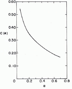
Fig. 3. Graph of C(α) against α. This is a modified graph. In the original version (Reference BernshteynBernshteyn, 1929) C(α )is presented for P in tonnes, h in meters and σ in kg cm-2.
To demonstrate the use of Equation (10a) Bernshteyn computed the σmax due to a railroad car weighing 24 Mg for a 70 cm thick ice plate as follows.
Assuming that for Volga ice E = 550 000 Mg/m2 and v = 1/3, he obtained
l = (D/γ)¼ = 11.50 m.
He then assumed that the effect of the weight of the railroad car may be represented by a load uniformly distributed over a circular area with radius a = 1.54 m. Hence, α = a/l = 0.134. From Figure 3 it follows that C(α) = 0.417. For the above values Equation (10a) yields
The next step is to check whether αmax ≤ σt. For additional numerical analyses, refer to Reference BernshteynBernshteyn (1929).
Other numerical examples, based on the Bernshteyn solution, were presented by Reference VolkovVolkov (1940) and by Reference Bregman and ProskuryakovBregman and Proskuryakov (1943, part IV, section 7).
The determination of the load Per for a floating infinite plate based on Equations (8) and (9) and the assumption that the load q = P/(πa2) is distributed uniformly over a circular region of radius a, was also presented by Reference WymanWyman (1950), Reference Lagutin and ShulmanKubo (1958), and Reference Savel'yevSavel'yev (1963, section 5). Wyman obtained for the load Per the expression
This is identical to Equation (10a) noting that
The determination of Per , assuming that the uniform load is distributed over a square area with sides b, was obtained by Golushkevich and included in his doctoral dissertation Footnote * . The derived expression yields loads which are very close to those obtained from Equations (10a) or (10b).
Solutions for an infinite plate were also presented in the books by Reference SchleicherSchleicher (1926), Reference Korenev and RabinovichKorenev (1954), Reference Korenev and RabinovichKorenev (1960), and Reference KorunovKorenev and Chernigovskaya (1962).
A solution for the infinite plate subjected to a row of equidistant loads was presented by Reference WestergaardWestergaard (1923) in terms of a trigonometric series. Solutions to similar problems (periodic load distribution), also in terms of trigonometric series, were presented by Reference LinellLewe (1923), Reference NevelMüller (1952), and Reference PanfilovPanfilov (1963[a], Reference Panfilov1964[a]). The book by Reference Shekhter and VinokurovaShekhter and Vinokurova (1936) discusses related problems.
Since Equations (9) is linear, it appears that when the plate is subjected to several loads, the method of superposition should be used. This idea was demonstrated by Reference KerrKerr (1959[b]) for the solution of the floating plate subjected to a row of equidistant loads. A major advantage of this approach is that the distribution of the loads on the floating plate may be aribtrary, whereas the use of trigonometric series is suitable only when the loads act along straight lines, all loads along a line are of the same intensity and distribution and the distance between them is the same.
The analysis of floating ice plates for arbitrary load distributions may be greatly simplified by utilizing influence surfaces (Reference TimoshenkoTimoshenko and Woinowsky-Krieger, 1959). Such charts were presented by Reference Pickett and RayPickett and Ray (1951) for concrete pavements. Influence surfaces for bending moments, more suitable for ice-plate problems, were presented by Palmer (unpublished). Palmer's charts may also be used for the determination of the load distribution on a plate that yields the largest possible bending moment. An attempt to solve such a problem without influence surfaces was made by Reference Nevel and AssurNevel and Assur (1968). They considered the problem of the most unfavorable distribution of crowds on a floating ice plate from the point of view of bearing capacity, based on Equations (8). Using influence surfaces, this problem was recently analyzed by Palmer (unpublished).
Bernshteyn's Equation (10a) is shown as a solid line in Figure 4. Reference SmirnovShulman (1946) simplified Equation (10a) by replacing the curve for 0.07 < α < 0.65 with a straight line described by the expression
P er = 0375σt(h2+7.8a(γ/E)1/4h5/4) (12a)
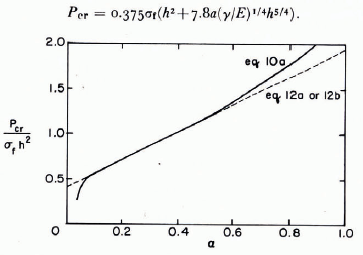
Fig. 4. Comparison between Equations (10) and proposed simplified relations.
Based on the idea of a straight-line approximation, Reference PanfilovPanfilov (1960[b]) proposed the expression
p er = 0.375(1+4.1α)σfh2 (12b)
It should be noted that Panfilov's approximation, Equation (12b), is the same as the one presented by Shulman, since for v = 0.3
The following approximation was also proposed by Reference PanfilovPanfilov (1960[b]):
However, since it is not much simpler than the exact expression, Equation (10a), its usefulness is questionable.
Panfilov (1964[b]) attempted to derive another approximate expression for pet , assuming that the deflections of a floating ice plate subjected to a concentrated force P may be expressed approximately as:
where
From the equilibrium equation

Panfilov determined the only unknown, w0, as
Comparing the resulting w(x,y) with the exact solution and finding that the agreement is relatively close, Panfilov determined the bending moments using the relations (Reference TimoshenkoTimoshenko and Woinowsky-Krieger, 1959, p. 81)

and the approximate w(x,y) given in Equation (15). For the bending moments under the load P, he obtained
Equating this expression with Mer = σt2/6, Panfilov obtained, for v = 1/3, the expression Per = σth2 (21)
At this point, il should be noted that the fact that the approximate and exact deflections are relatively close (in the sense of comparing two graphs) does not imply that the second derivatives are also close. Thus, for example, whereas the exact solution for the classical plate theory based on Equations (9) yields infinite moments under the concentrated load P, Footnote * Panfilov's approximate solution yields the finite value shown in Equation (20). This point may be demonstrated further by comparing the graphs for the bending moment Mx(x, o) based respectively on Equation (15) and on the exact solution. It may be shown that although the deflections are relatively close, the bending moments based on Equations (15) do not approximate closely the actual bending moments, especially in the vicinity of the load.
Other approximate solutions for the infinite plate were discussed by Reference KorunovKorunov (1967). Assuming that Bernshtcyn's Equation (10a) is the correct expression for predicting the bearing capacity, Korunov proposed the empirical expression (for h in cm)

and then showed that for special situations, this agrees with the results of Equation (10a). Noting that Equations (22) is based on σt = 24 kg/cm2 = 2350 kN/m2, it follows that
Note that, according to Equations (22), for a given σt , Per is proportional to the second term in Equation (12a) or (12b) z, namely to h5/4 whereas Equations (21), derived for α = o, is proportional to the first term, namely to h2. Note also the difference between Equation (7), suggested by Korunov, and Equations (21), derived by Panfilov. A comparison of various approximate expressions for Per with the one based on Equation (10a) is shown in Figure 5.

Fig.5 A comparison of apporixmation for Per with exact values.
It appears that, instead of deriving numerous approximate expressions for Equation (10a) that differ substantially from each other and are not much simpler than the exact expression,Footnote * it should first be established whether Equation (10a) is suitable for predicting the bearing capacity of floating ice plates for loads of short duration. This and related questions will be discussed later.
Solutions for the floating semi-infinite plate with a free edge subjected to lateral loads were presented by Reference ShapiroShapiro (1943) and by Golushkevich in his doctoral dissertation (see footnote on p. 234) using Fourier integral methods. Shapiro's results were verified and extended by Reference NevelNevel (1965).
Reference ZylevZylev (1950), using Equations (8), presented calculations of the bearing capacity of a floating semi-infinite ice plate subjected along its free edge to vertical and horizontal loads. However, Zylev's approximate solution of Equations (9) for the vertical load, recently included in a number of books (e.g. Reference Korzhavin and ButyaginKorzhavin, 1962; Reference ChikovskiyButyagin, 1966) is incorrect, as shown below.
For the semi-infinite plate shown in Figure 6, Zylev assumes an approximate solution of the form
w(x,y) = [coash (αx) + $$ sinh (αx)] f(y)(23)
where

Substituting Equations (23) into Equations (9) with q = o, he obtains an ordinary differential equation of fourth order for f(y). . To determine the four constants, Zylev uses two regularity conditions at infinity and the conditions
My(x,o) =o (25)


Fig. 6. Floating semi-infinite plate with free edge subjected to loade P.
It should be noted that for the chosen deflection surface given by Equations (23),
![]() is discontinuous along y-axis, which is not the case in an actual ice plate. Also,
is discontinuous along y-axis, which is not the case in an actual ice plate. Also,
![]() is discontinuous along the y-axis; this implies that for the assumed deflection surface there exists a line load along the j-axis. This is in contradiction with the assumed plate load shown in Figure 6. Furthermore, along the free edge, where the largest stresses are anticipated, the boundary conditions for a free edge are not satisfied. Therefore, the validity of Zylev's solution for the semi-infinite plate, even for the determination of an approximate Per
is questionable.
is discontinuous along the y-axis; this implies that for the assumed deflection surface there exists a line load along the j-axis. This is in contradiction with the assumed plate load shown in Figure 6. Furthermore, along the free edge, where the largest stresses are anticipated, the boundary conditions for a free edge are not satisfied. Therefore, the validity of Zylev's solution for the semi-infinite plate, even for the determination of an approximate Per
is questionable.
According to Zylev's results, the largest bending moment takes place at the point x = o and y = 1.14D1/4. On the basis of this analysis
Per = 0.8λ[I -exp (- λ)]-1 σth 2 (27)
where
λ = 0.248b/D1/2 (28)
According to Shapiro's results, σmax takes place under the load. Utilizing Equations (8), the load at which the first crack occurs becomes
Per = S(α)σth2(29)
where S(α) for v = 0.36 is given in Figure 7.
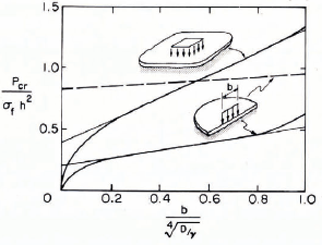
Fig. 7. Comparison of analytical results
Reference PanfilovPanfilov (1960[a])compared the values of the load Per for the infinite plate as well as the semi-infinite plate. The corresponding graphs are shown in Figure 7. This comparison shows that the Per for the semi-infinite plate, according to Zylev (dashed line), is much higher than the Per according to Shapiro and Golushkevich. If 0 < b/l < 0.5, it is even higher than the
Pcr of the infinite plate. In view of this comparison and the obvious errors contained in Zylev's solution, it is suggested that Equations (27) should not be used for the analysis of the semi-infinite plate with a free edge.
According to Reference PanfilovPanfilov (1960[a]) it follows from. Figure 7 that for 0.07 < b/l < 1.0, the value of Perr for the infinite plate is about 2.45 times the value of Perr for the semi-infinite plate. Λ more precise relationship is shown in Figure 8.

Fig. 8. Relation between critical loads for the infinite plate and semi-infinite plate
On the basis of the graph for the semi-infinite plate shown in Figure 7, Reference PanfilovPanfilov (1960[a]) proposed the following approximate expression for the interval 0.07 < b < I:
P er = 0.16(1 +2.30b/l) σth2 (30) Reference PanfilovPanfilov (1964[b]) also attempted to derive an approximate expression for P er for the problem shown in Figure 6, assuming that
However, the result obtained, similar in form to Equation (21), is of questionable value. The objections raised in connection with Equations (21) also apply here. It should also be noted that the deflection surface, Equations (31), does not satisfy Equations (9) or the boundary conditions along the free edge, where the stresses are determined for use in Equations (8).
The semi-infinite plate subjected to equidistant loads P along the free edge was analyzed by Reference WestergaardWestergaard (1923). Similar problems were solved by Reference PanfilovPanfilov (1963[b], [d]). The books of Reference Shekhter and VinokurovaShekhter and Vinokurova (1936) and Reference KorunovKorenev and Chernigovskaya (1962) also contain solutions to related problems.
The solution for the semi-infinite plate, simply supported along the straight edge and subjected at any point of the plate to a concentrated force P, as shown in Figure 9, was derived by Reference KerrKerr (i959[a]). Using the method of images, the following exact closed-form solution was obtained:
Palmer (unpublished) utilized this solution to construct a number of influence surfaces for bending moments.
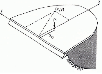
Fig. 9. Floating semi-infinite plates, simply supported along the straight edge and subjected to a load Pat (x0 0).
A numerical solution for the semi-infinite plate, clamped along the edge and subjected to a force P at a point on the plate, was presented by Reference Korenev and RabinovichKorenev (1960).
An analysis of a floating infinite strip, free along both edges and subjected to a lateral load, utilizing the Fourier integral method, was presented by Reference ShapiroShapiro (1942). Detailed results for similar problems were presented by Reference PanfilovPanfilov (1966[a], 197o[a]).
The solution for a floating infinite strip, simply supported along both edges and subjected to a concentrated force P at any point on the plate, was presented by Reference KerrKerr (1959^]), utilizing the method of images. The resulting deflection was given as a rapidly converging infinite series of fundamental solutions for the infinite plate. A solution for this problem was presented by Westergaard (1923) in terms of Fourier series. Reference NevelNevel (1965) presented a solution in terms of a Fourier integral. A solution for a similar problem was presented by Reference PanfilovPanfilov (1966[a]) also using the Fourier integral method.
Reference KerrKashtelyan (1960) presented calculations for the direct determination of Pt (that is by eliminating step (iii) in the above procedure) which are based on the observation that the carrying capacity is reached when the wedges which form initially break off. However, Kashtelyan's solution for the wedge-shaped plate on which his calculations are based, may not be accurate enough, as shown in the following.
For the rectangular corner plate with free edges, shown in Figure 10, Kashtelyan assumed an approximate solution
w(x,y = f exp [-α(x+y)] cos (αx) cos (αy)(33)
where α and f are unknown parameters.
From the condition


Fig. 10. Floating quarter-infinite plate subjected to a land P at its apex.
Kashtclyan obtained
f = 4α2 P/y.(35)
Then, utilizing the Bubnov-Galerkin method, for a one-term approximation he used

and determined from it
α = (γ/4D)¼ (37)
Thus, according to Equations (35)
f = 2P/(γD)½ (38)
It should be noted that the above analysis contains errors: because the assumed deflection given by Equations (33) does not satisfy the boundary conditions of zero moments and zero shearing forces along the free boundary, Equations (36) is not complete. Also, the work term of the force P is missing. According to the principle of virtual displacements, the proper Bubnov-Galerkin equation for a one-term approximation w =fwl(x,y), where. f is the only unknown, is

where Mx and My are given by Equations (19) and

Note, however, that the purpose of Equations (36) is not to determine f but α.
Comparing thc f-valuc given by Equations (38) with the corresponding value of the exact solution of an infinite plate, f - P/8(γD)½ , and the (incorrect) approximate solution by Reference ZylevZylev (1950) for a semi-infinite plate, f = — P/2(γD)½ Reference KerrKashtelyan (1960), without justification, generalized his solution for a wedge of any opening angle ø (Fig. 11) by assuming that

Fig. 11. Floating wedge loaded at its apex.
an equation which satisfies Equations (38) for ø = π/2 and the other two cases (ø = 2π and ø = π) mentioned above. Utilizing Equations (8), he then obtained for the “failure load” of a floating wedge plate of opening angle ø the expression
Note that, according to field observations made by Kashtelyan (1960), when ø <120°, Per = Pt Thus, according to Equations (42) for a floating wedge with ø = 1/2π, as shown in Figure 10, the breakthrough load is
Observations in the field indicate that the failure mechanism of a semi-infinite plate subjected to a force P at the free edge proceeds as follows: First a radial crack forms, which starts under the load and propagates normal to the free boundary. This is followed by the formation of a circumferential crack that causes final failure, as shown in Figure 12.

Fig. 12. Failure mechanism of a floating semi-infinite plate subjected to a load P at the free edge.
According to Kashtelyan, the failure load for this case is equal to the failure load of two free-floating wedges, each of opening angle ø = π/2
Namely,
In a similar way, Kashtelyan determined the Pt for an infinite plate. Assuming that n is the number of radial cracks and that the n formed wedges are all of equal opening angle, i.e. ø n = 2 π/n, as shown in Figure 13, the following expression for the failure load results:
Noting that n = 2π/øn, this expression may also be written as
where φn is the opening angle of the formed wedges. Note that with decreasing φη the load Ptt in Equations (44) decreases and that the above approach does not take into consideration the effect of the wedge-in moments along the cracks.

Fig. 13. Failure mechanism for a large floating ice plate subjected to a load P.
Kashtelyan showed that the results of 150 tests on floating ice plates agree closely with the bearing capacity values based on Equations (43) and (44). In view of the errors discussed above, however, this agreement is not convincing.
An approximate solution for the quarter plate with free edges loaded at the apex, was also presented by Reference WestergaardWestergaard (1948).
An exact, closed-form solution for the quarter plate simply supported along the edges and subjected at any point of the plate to a concentrated force P was presented by Reference KerrKerr (1959)[a]), using the method of images.
The response of a narrow infinite wedge resting on a liquid base, as a beam problem is described by an ordinary differential equation with a variable coefficient. This equation was solved by Reference DuffDieudoneé (unpublished) by means of the Laplace method of integration Reference NevelNevel (1958) solved it using the method of Frobenius. Nevel's solution consists of a sum of four infinite series which were evaluated by Reference NevelNevel (1961) and are presented as graphs. An approximate solution for large values of x was presented by Hetényi (1946).
An early attempt to determine the bearing capacity of a floating ice plate utilizing a floating wedge solution was described by Reference PapkovichPapkovich (1962, p. 424-26). In this analysis it was assumed that the wedge response is governed by a modified bending theory of beams by stating the base parameter as (Fig. 14)
k(x) = γ[b+2x tan (φ/2)](45)
and the flexural rigidity as
where y is the weight per unit volume of the liquid. The term (I – v2) was apparently included to get plate action for the wedge. The deflection was assumed to have the form
w(x) = A exp (- λx) cos (λx)(47)

Fig. 14. Floating wedge-shaped plate subjected to a toad p = qb.
where
and the unknown constant A was determined by minimizing the total potential energy, Substituting the determined
into Equations (47), yielded the deflection
The bending moment was
and the stresses in the upper and lower fibres were obtained as
From the condition dσ/dx = o, the position of the largest stress x = π/(4λ), was determined. Substituting this value into the above equation, it follows that
Utilizing the failure criterion given by Equations (8), namely σmax = σ t, it follows from Equations (51), using Equations (48) and (49), that
Noting Equations (48), the above expression for the failure load of a wedge of opening angle φ may also be written as
Pointing out that an ice plate breaks under the weight of an icebreaker into wedges and that Pt in Equations (53) is of the form
Papkovich suggested that Equations (54) be utilized for the determination of an empirical expression for the breakthrough load of an ice plate by determining the parameters A1 and A2 from field test data.
It should be noted that although Equations (53) is only an approximation (for example, the corresponding bending moment at x = o is not zero), its dependence upon A is identical with that in Equations (12a) and (12b) for the infinite plate and Equations (30) for the semi-infinite plate, respectively. Even the term b(γ/E)½ appears in the proper place. This observation will be of importance when discussing the test data presented by Reference PanfilovPanfilov (1960[a]).
For solutions to other plate problems for which response is governed by Equations (9) reference is made to the books by Reference SchleicherSchleicher (1926), Reference Shekhter and VinokurovaShekhter and Vinokurova (1936), Reference KorenevKorenev (1954, 1960) and Reference KorunovKorenev and Chernigovskaya (1962), to the survey articles by Reference KorenevKorenev (1957, 1969) and Reference Savel'yevSavel'yev (1969), and to the literature on the analys.s of highway and airport pavements.
When a floating ice plate seals the liquid base, then in addition to the buoyancy pressure kw(x,y), the liquid exerts also a uniform pressure p * on the plate. In these cases, an additional condition has to be imposed on the solution to reflect this situation. The unknown p * is determined from this condition.
If the assumption that the liquid is sealed and incompressible is justified, then this additional condition is

where the integration extends over the domain of the plate A.
Floating plates subjected to Equations (55) were analyzed by Reference NevelNevel (1963) and Reference KerrKerr (1965, 1966). Reference Kerr and PalmerKerr and Becker (1967) solved plate problems by assuming that the scaled liquid is compressible. They showed that the effect of the sealed liquid depends not only upon its relative compressibility but also upon the sealed volume: the larger the sealed volume, the smaller the sealability effect. This result suggests that the use of Equations (55) for the analysis of an ice plate that covers a river or a lake, as suggested recently by Mahrenholtz (1966) is not justified.
The analyses reviewed in this section are based on Equations (9), which is the differential equation for a homogeneous and isotropic thin elastic plate. In an actual floating ice plate, the material parameters vary across the thickness of the plate; hence, the floating ice plate is inhomogeneous. This variation is very pronounced in sea-ice plates as well as in a plate whose upper surface is subjected to very low air temperatures.
An early attempt to take into consideration the variation of Young's modulus E by Reference Bregman and ProskuryakovBregman and Proskuryakov (1943, p. 73) is incorrect because the investigators did not take into consideration that when £ varies across the plate thickness the resulting stress distribution is not linear.
According to recent papers by Reference Newman and ForrayNewman and Forray (1962), Reference PanfilovPanfilov (1966[b]), and Reference Assur and ÖuraAssur (1967), when Young's modulus E varies with the plate thickness h, and Poisson's ratio v is assumed to be constant, Equations (9) is still valid if the flexural rigidity is

and the position of the reference plane is determined from the condition

In order to utilize the available solutions of Equations (9) for nonhomogeneous plates with E = E(z), it had to be shown that, except for Equations (56), the corresponding boundary conditions are the same as those for homogeneous plates. This was done recently by Reference KheysinKerr and Palmer (1972), who systematically formulated this problem utilizing Hamilton's principle in conjunction with the three-dimensional theory of elasticity.
Reference KheysinKerr and Palmer (1972) also showed that even though the plane-section hypothesis is assumed, the resulting bending stress distributions are not linear across the plate thickness. An example is shown in Figure 15. This finding suggests that the well-known stress equation
utilized by various investigators in conjunction with Equations (8), or for the determination of the failure stress σt from tests on floating ice beams, may not be applicable in general.

Fig. 15. Stress distribution in an ice plaie for the shown E(z).
Method Based on Visco-Elastic Theories
It was observed in the field that for loads which do not cause an instantaneous breakthrough, the ice plate deforms at first elastically and then, with 'progressing time, continues to deform in creep, especially in the vicinity of the load.
Two characteristic deflection-versus-time curves for fixed loads P are shown in Figure 16. Curve I represents the case when, after a time, the rates of deformation diminish and the ice plate and load come to an apparent standstill. This curve corresponds to a safe load for any length of time under consideration. Curve II represents the case when, after a time, the rates of deformation increase and after a time if the load breaks through. Thus, the load that corresponds to curve II is safe for time t < ts, but then it has to be moved to another location to prevent breakthrough.

Fig. 16. Two characteristic curves of deflection versus time.
The above field observations suggest that, for an analytical determination of breakthrough loads which do not cause immediate failure, a visco-elastic analysis has to be conducted.
It appears that the small-deformation theory of plates may be sufficient for plates which follow curve I. However, the analysis of plates which respond according to curve II is more complicated because in the vicinity of the load, a region of prime interest, the small deflection theory may not be valid when it is approaching rf. Also, as the plate deflections increase, the plate may start to crack—a phenomenon not predicted by the usual theories of visco-elastic continua. To predict cracking, a separate failure or crack criterion has to be used. Also, after the first crack takes place, the analysis gets even more involved because of the introduction of additional, often irregular, plate boundaries.
For an analytical determination of a “safe” load P < Pt and a “time to failure” t f, it is desirable to have one visco-elastic theory for floating ice plates which for time t = 0 yields the elastic response and for t > 0 yields responses according to curves I or II, depending upon the load and the material parameters of the ice (which in turn depend upon the temperature distribution, salinity, etc.). This theory should be supplemented by a crack or failure criterion valid for the elastic and visco-elastic range.
The elastic theory in conjunction with the crack criterion σmax = σt discussed above could, if proven correct, be a special case of such a general theory.
Another failure criterion was proposed by Reference ZubovZubov (1942) and by Reference KorenevKobeko and others (1946[b]). On the basis of their test data, they concluded that for loads of short or long duration, a floating ice plate fails under the load when a certain deflection wt is reached: namely, when
wmax = wf (58)
According to Reference KorenevKobeko and others (i946[b]) for this criterion it does not matter whether the plate deflections are purely elastic or visco-elastic, as shown in Figure 17.

Fig. 17. The failure criterion based on plate defections.
Equation (58) was also adopted by Savclyev (1963, section 5) for the study of the effect of temperature and salinity on the carrying capacity of a floating ice cover.
Panfilov (1961 ) proposed the above criterion for floating ice plates which are cracked in the dished area. His justification was that then water begins to flood the upper surface of the plate, with a resulting loss of base pressure in this area. It may be added that the flooding of the upper surface near the load also raises the temperature of the upper layers of the plate to about 0°C, thus decreasing the strength of the ice in the area of high stresses.
From experiments on floating ice plates with plate thicknesses h from 1 to 6 cm and temperatures from —3°C to —8.5°C, Panfilov (1961) found, for A and wt in centimeters, that
wt = 2.2 h1/2 (59)
In this connection note that using the criterion w max = wt in conjunction with Equations (59) and the solution for an infinite (uncracked) elastic plate subjected to a concentrated load P
it follows that

Thus, according to Equations (59), the breakthrough load. Pt is proportional to h 2. It may be of interest to note that if the largest deflection of the plate under consideration is expressed by the equation
where ϵ is a coefficient, then a Pt expression of the form shown in Equations (54) corresponds to the criterion
where α and β are coefficients.
Test data are needed to establish whether the failure criterion, Equations (58), and its special forms Equations (59) or (61), are indeed valid for elastic as well as visco-elastic deformations.
In the early attempts to take time effects into consideration for floating ice plates, one approach, presented by Reference Bregman and ProskuryakovBregman and Proskuryakov (1943, p. 53), utilizes the solutions for elastic bending and tries to fit the experimental data by modifying the elastic constants. In another approach presented by the South Manchurian Railway Company Footnote * in 1941, the elastic results are multiplied by a time factor, for example (I + atβ where t is time and α and β are constants to be determined from experimental data. However, these approaches have no rational foundation and their results are of questionable value.
Another early approach is based on a hypothesis by Reference ZubovZubov (1942, p. 49) which states that deflections of ice plates, especially at comparatively high temperatures, are caused mainly by the vertical shearing forces. To verify Zubov's assumption, Reference ZvolinskiyZvolinskiy (1946) analyzed a plate resting on a liquid, assuming that the deformations are entirely due to shearing action and that for creep deformations the material obeys Newton's law of viscosity. Although the resulting differential equation was relatively simple, the obtained solution was rather involved because of the prescribed initial conditions. Quoting a translation of Reference ZvolinskiyZvolinskiy (1946, p. 21): “In this formula the result is not self evident, and analyzing it does not help us to visualize the picture of the phenomenon”.
Zvolinskiy used, for the initial condition, the elastic deflection surface caused by shear only. However, according to the experiments by Bernshteyn (1929, fig. 18) shortly after the load is placed, the deflection surface agrees closely with the elastic deflection surface due to bending. Also, since the elastic deflections are relatively small, the effect of assuming that the elastic deformations are zero seems to be negligible compared with the introduced error of assuming shear as the only force responsible for creep deformations. This assumption was made by Reference KerrKerr (1959[b]), who attempted to simplify Zvolinskiy's analysis in order to study the characteristic features of the creep deformations based on Zubov's hypothesis.
Recorded observations of the effect of static loads on the deformation of floating ice fields, for example by Bernshteyn (1929, p. 48) and Zubov (1942, p. 146), showed that in some cases the rates of deflection decreased after the load was placed and after a certain time interval the plate came to a standstill, whereas in other cases the rates of deflection increased until the plate collapsed under the load as shown in Figure 16. The observed decreasing and increasing rates of deflection should result from a general formulation of the problem. However, because of the simplifying assumptions made, Reference KerrKerr (1959[b]) had to set up two separate formulations for the decreasing and increasing rates of deformation, in order to obtain this response. Although some of the resulting solutions did agree with deflection expressions given by Zubov (1942, p. 24; 1945, p. 148), because of the various assumptions made, these results should be used with caution for the determination of breakthrough loads.
The assumption that the predominant deformations of a floating ice sheet are caused by shearing forces was also made by Krylov (1948).
The intense development of the linear theory of visco-elasticity after World War II had its effect also on the formulation of ice-plate problems. In 1947 Golushkevich (referred to by Reference Klyucharev and IzyumovKheysin (1964)) presented an analysis assuming that ice behaves elastically for volumetric deformations and visco-elastically for deviatoric deformations. His formulation was based on the linear bending theory of plates, linear constitutive equations, and the assumption that the material parameters do not vary across the plate thickness. The obtained equations were linear. The special case of an incompressible material was analyzed in detail.
A general formulation for visco-elastic plates, based on the linear bending theory of plates and the assumption that the constitutive equation is a linear relation of differential operators, was presented by Reference GarbaccioFreudenthal and Geiringer (1958). The utilization of this equation for floating ice plates was discussed by Reference Klyucharev and IzyumovKheysin (1964). As a special case, Kheysin analyzed an infinite ice plate subjected to a concentrated force P, assuming that the ice is incompressible for volumetric deformations and that it responds like a Maxwell body for deviatoric deformations. A similar problem which arises when the load is distributed uniformly over a circular area, was analyzed by Reference NevelNevel (1966), who also presented graphs and a comparison with the results of a test. Reference YakuninYakunin (1970) presented solutions for various load distributions, assuming that the ice responds like a four-element model; namely a series combination of a Maxwell and a Kelvin model. Except for the paper by Yakunin, in the above analyses it is assumed that the material parameters are constant throughout the plate.
As discussed in the preceeding section, in an actual floating ice cover the material parameters vary with depth. In an attempt to take this into consideration, Reference YakuninYakunin (1970) derived an approximate formulation for a varying modulus of elasticity and coefficient of viscosity, and solved it for a variety of load distributions. He found that, as in the elastic case, the variation of material parameters across the plate thickness has a profound effect upon the stresses in the ice cover.
A visco-elastic analysis of the ice cover based on Reissner's theory of plates, which takes into consideration the effect of bending as well as shearing forces upon the deformations, was recently presented by Reference GarbaccioGarbaccio (1967, 1968). Garbaccio assumed that the ice responds like a series combination of a Maxwell and a Kelvin model and that the material parameters are constant throughout the ice plate.
Panfilov (1961), citing observed short-comings of linear theories, derived a differential equation for floating ice plates, based on the linear bending theory of plates and the nonlinear visco-elastic constitutive equations proposed by Reference VoytkovskiyVoytkovskiy (1957, igbo). Additional derivations, along the same line, were presented by Reference PanfilovPanfilov (1970[b]) who, however, gave no solutions to the derived differential equation.
An attempt to analyze the time-dependent stresses of an ice cover, using a non-linear constitutive equation, was presented by Reference DailyCutcliffe and others (1963).
The linear bending theory and a non-linear constitutive equation was also used by Reference GarbaccioGarbaccio (1967, 1968) to analyze ice-plate problems. Garbaccio attempted to obtain an approximate solution of the resulting non-linear formulation by means of a linearization technique.
In the absence of reliable analyses for predicting the bearing capacity of ice plates subjected to loads of long duration, Reference PanfilovPanfilov (1961), constructed from field test data the graph shown in Figure 18. In this graph tt is the time period between placement of the load and breakthrough Pf(o) is the magnitude of the load just sufficient to break through immediately after placement on the plate (at ti = o), as discussed in the previous section,Footnote * and Pi(t) is the load that breaks through after a time ti From the shown graph, it follows that Pi(ti) < Pi(o) for ti > o. Thus, for example, a load that has to park safely on the ice plate for 6 h should be smaller than 0.4Pi (0), where Pt(o) is determined from a separate analysis. To represent the graph shown in Figure 18 analytically, Panfilov proposed the expression for ti in hours,
Solving this equation, the “safe” storage time is obtained as the time that is smaller than


Fig. 18. Failure load as a function of time to failure.
A graph similar to the one shown in Figure 18 was also presented and discussed, by Reference AssurAssur ([1962][b]).
Korunov (1968) pointed out that Equations (62) was obtained from tests on ice plates under specific conditions. He then proposed the following modification of Equations (63):
where K and n are correction coefficients which take into consideration the shape of the load and the outside temperature.
Other expressions of the type shown in Equations (62) were presented and discussed by Reference PanfilovPanfilov (1970[b]). For a related discussion refer to Yakunin (1970).
Methods Based on the Yield-Line Theory or Limit Analysis
The theory of yield lines was utilized for the analysis of continuously supported plates by Reference KashtelyanJohansson (1947) and Reference BernellBernell (1952). Reference PerssonPersson (1948) used it for the analysis of a floating ice plate. Assuming that the yield-line moment per unit length is M o, Persson obtained for the case shown in Figure 2,
Using a similar approach, Reference AssurAssur ([1962][b]) presented, for the breakthrough load, the expression
The method of limit analysis was used by Reference MoskatovMeyerhof (1960) for the analysis of the bearing capacity of floating ice plates. Assuming that the ice plate is thin, rigid ideally plastic, that it can, without cracking, resist a full plastic moment M0 , and that the ice obeys the Tresca yield condition, Meyerhof obtained for the case shown in Figure 2
Assuming that the floating ice plate prior to failure is cracked radially into numerous wedges, Meyerhof obtained for the same case
In an extensive discussion of Meyerhof's paper, Hopkins (Reference JanssonHopkins and others, 1961) questioned the degree of realism in approximating the mechanical behavior of ice by a rigid perfectly-plastic material. Hopkins, as well as Wood, also questioned the use of the Tresca yield condition.
Recently, Reference Cutcliffe, Cutcliffe, Kingery, Coble and KingeryCoon and Mohaghcgh (1972) also analyzed the floating ice plate by the method of limit analysis, but assumed that the ice obeys Coulomb's law. For the problem shown in Figure 2 they obtained
Additional results and discussions are presented by Reference MoskatovMeyerhof (1960) and Reference Cutcliffe, Cutcliffe, Kingery, Coble and KingeryCoon and Mohaghegh (1972).
Related results were published by Reference Korenev and RabinovichKorenev (1960, part II, §7) and Reference SerebryanyySerebryanyy (1960).
It should be noted that the often-used expression for the limit bending moment, Ma = σ0h2/4, is based on a stress distribution of a homogeneous plate as shown at (a) in Figure 19, whereas, because of the thermal gradient in the plate, the distribution of limit stresses could be, noting Reference PeschanskiyPeschanskiy (1945) and assuming that a full plastic moment does exist, as shown at (b) in Figure 19. Also, the assumption that the ice plate can, without cracking, resist a full plastic moment M0 may not be realistic, since its formation was not observed in the field. When using yield-line theory, it may be more realistic to work with “cracks” instead of “yield lines” and “wedge-in moments” instead of the “plastic moment M0”, especially along the radial cracks.

Fig. 19. Development of a full plastic bending moment in a homogeneous plate (a) and effect of a thermal gradient in the plate on this (b).
A comparison of the various Pt expressions presented above with the formula for Per given in Equation (10a) by Bernshteyn is shown in Figure 20. For comparison purposes, it was assumed that σo and that Mo = σo h 2/4 Note that a different number in the denominator of M0 only shifts a plotted graph vertically.

Fig. 20. Comparison of various expressions for Pt with the Per deduced by Bernshteyn in Equations (10)
Note that all graphs of Pt/( σoh2) against α obtained using plasticity methods show the same characteristics and that they may be represented by a straight line, as in Equations (12a) or (12b).
Comparison of Analytical and Test Results
General remarks
The mechanical properties of ice vary drastically in the vicinity of the melting (or freezing) temperature of about 0°C. Because the lower surface of a floating ice plate is usually at the freezing temperature, the plate response is obviously affected by this. This effect is especially severe when the upper surface is also subjected to temperatures near, O°C because then the temperature throughout the plate is close to the melting temperature.
To demonstrate the variations of temperature with time, consider a floating ice plate subjected for a long time to an air temperature of — 10°C. Assume that at time t = o the air
temperature rises to — I°C Then the corresponding temperature distributions for different times are as shown in Figure 21. Note that although the temperatures at the top and bottom surfaces are constant for t > o, the temperatures throughout the plate vary with time. Hence, if two identical tests are performed before a thermal steady state is established, the results may differ, depending upon the time (after the sudden outside temperature change) when a particular test is conducted.

Fig. 21. Temperature distribution in the ice sheet (schematic) for different times.
A similar situation occurs in the floating test beams used for the determination of the failure stress σt, because, after a beam is cut out from the ice, the side walls come in contact with the rising water and the outside air.
Another thermal problem may arise in a test when an ice cover in the field is loaded by pumping water into a large tank that rests directly on the cover, for then the bottom of the tank, which is made of metal or canvas, rests on the ice, and the upper surface of the ice plate in the contact region is subjected to temperatures near 0°C which may differ substantially from the outside air temperature. This type of loading usually causes a change in the stress distribution and a lowering of the strength of the ice in the area where failure usually starts, thus affecting the test results.
These and related questions, such as the effect of a sharp drop of the air temperature, the rate of loading, the penetration of water through the ice plate during loading, etc., have to be considered when the test data of floating ice plates are correlated with corresponding analytical results. In the following, various test results are presented and correlated with analyses discussed previously.
Effect of bending and shearing forces on the defection of ice cover
As shown in the previous sections, an analytical determination of the breakthrough load utilizes a formulation for the ice cover. In order to simplify the necessary analyses, such a formulation contains a number of assumptions. It is essential that the assumptions made be justified, from a physical point of view, since otherwise the analytical results may have no relevance to the actual problem under consideration.
One such assumption, included in the derivation of Equations (9), states that a straight line normal to the reference plane, remains straight and normal to the deformed plane (sometimes called the Kirchhoff hypothesis). Physically, this kinematic assumption implies that the deflections are caused only by bending stresses, and that the effect of shearing forces is negligible. This assumption, discussed at length in books on strength of materials, has been proven to be justified for the elastic response of slender beams and thin plates made of a variety of materials.
On the other hand, basing his view on field observations, Reference ZubovZubov (1945) suggested that the deflections of an ice cover are mainly caused by shearing forces and hence the effect of bending upon the deflections is negligible.
Because the resulting equations are used for the analytical determination of Pt for additional examples see Panfilov (1963[c]), it is essential to determine whether Kirchhoff's or Zubov's assumption is to be used for the formulation of ice-cover problems. In this connection, note that the plate deflections due to a load q which is distributed over a circular area, based on Equations (9), are, according to Reference WymanWyman (1950),

where λ = (y/D)1/2 whereas the differential equation for an ice plate, according to Zubov's hypothesis, is
where G is the shear modulus and the corresponding deflections are

where I0 , K0 , II and KI are Bessel functions and κ = [y/(Gh)]1/2. To show the different nature of the deflection curves based on these two assumptions, the Equations (70) and (72) were evaluated numerically for h = 10 cm, v = 0.3 and E = 10 500 kg/cm2 (10.7 MN/m2). For a/h = I and 5 the corresponding values of G were determined using the condition that the largest deflections w(o) for both theories are equal. The results are shown in Figure 22.
Note that the response of an ice cover according to Zubov is identical to the response of the shear layer in the Pasternak foundation as shown by Reference KerrKerr (1964).

Fig. 22. Deflection curves according to bending and shear theories.
As early as 192g, Bernshtcyn compared the deflections of an ice field on the river Volga subjected to loads of short duration, at air temperatures of — 15°C < T < —7°C, with corresponding results based on Equation (g). This comparison is shown in Figure 23. Since the agreement is very close, it was concluded that the use of Equations (9), and hence Kirchhoff's hypothesis, is justified for the formulation of problems of ice plates subjected to loads of short duration.
Reference ShmatkovShmatkov (1968) compared test data of an ice plate on lake Baykal, subjected to a vertical load of short duration but at air temperatures of about 0°C, with analytical results based on Equations (9) and (71). This comparison is shown in Figure 24. On the basis of these data Shmatkov concluded that at air temperatures of about 0°C the deformations are mainly caused by shearing forces.

Fig. 23. Comparison of ice-plate deflections due to loads of short duration at 15 C < T < -7°C

Fig. 24. Comparison of ice-plate deflections due to loads of short duration at 0°C
This conclusion raises the question of the effect of the ice temperature upon the range of validity of Equations (9) and (71) for the formulation of ice covers. A comparative study involving more test data, especially at air temperatures near 0°C, is urgently needed to clarify this important question. In these tests, a special effort should be made to separate the elastic from the non-elastic deformations. It may also be advisable to note the difference between the crystallographic structure of an ice cover formed over a lake in which the water is essentially at rest, and that over a river in which the. water moves at a certain velocity, and the effect of this difference upon the mechanical properties of an ice cover.
Determination of Pt(o)
Test results and their relationship to the allowable load given by the analogy method were discussed by Reference Kobeko, Kobeko, Shishkin, Marey and IvanovaKlyucharev and Izyumov (1943) and by Reference KorenevKobeko and others (1946[b]). Reference GoldGold (1960) compared Equations (4) with the field results of the Canadian pulp and paper industry. The conclusion from this comparison was that the formula given in Equations (4) is not sufficient for the determination of failure loads, since the presence of cracks, thermal stresses, and natural variation in effective thickness is not taken into consideration. Another reason could be that the failure load Pt is not proportional to h2 but may be a more complicated function of k, as indicated by the expressions in Equations (10a) and (12a). Additional results were presented recently by Reference Gold, Gold, Black, Trofi–menkov and MatzGold (1971).
In order to establish which of the various formulas for Per and Pt(o) obtained using the criterion σmax = σat are suitable for predicting the carrying capacity of a floating plate subjected to loads of short duration, the values of Pt (o) obtained analytically are next compared with corresponding results from tests conducted on floating ice plates.
Since the analyses are based on an elastic theory, only the results of tests with very short loading times to failure are of interest. Such tests were recently conducted by Reference PanfilovPanfilov (1960[a]) in the laboratory as well as in the field. The laboratory tests were conducted at — 10°C. The floating plate was loaded by means of stamps of the dimensions shown in Figure 25. The loads were placed statically at rales which caused breakthrough within 5 to 20 s. Hence the loads were of short duration. In addition to the failure loads Pt, loads at which the first radial crack occurred Pet were recorded. The laboratory tests were conducted with fresh- and salt-water ice. The thickness of the ice plates varied from 7 to 30 mm. The field tests were conducted on thicker ice plates. An ice plate was loaded by placing a metal water tank on a structure which rested on the ice plate and simulated the contours of wheel loads. The ice strength σt was determined from floating cantilever tests with the load acting downwards. Additional details are contained in the paper by Panfilov (1960[a]).

Fig. 25. Results of laboratory tests for the failure of an infinite plate.
The results of 56 laboratory tests for the “infinite” plate are shown in Figure 25. The failures followed the usual pattern: First, the formation of radial cracks which emanated from the region under the load, then the formation of circumferential cracks at which time the load broke through the plate.
In Figure 25, Curve I represents Per/(σth2) according to the analyses by Bernshteyn (1929), Golushkevich in his dissertation in 1944, and Reference WymanWyman (1950). Curve II was proposed by Panfilov as representing the test data and is described by the equation
It was obtained by an averaging process. The test data show a scatter in a relatively narrow band.
Before proceeding with the discussion of these test results, a different concept is introduced for the evaluation of ice-plate tests. This is necessary because averaging curves, such as curve II, are not suitable for most engineering purposes.
From an engineering point of view, there is a need to determine safe loads at which an object may move slowly or park briefly on a floating ice plate, or breakthrough loads for the design of ice breakers at which the plate definitely collapses. These loads may be obtained by introducing into the results of field tests an upper envelope u and a lower envelope L, as shown in Figure 26. It is reasonable to expect that the area under envelope L contains safe loads and the area above envelope U the breakthrough loads. The area between the envelopes is the region of the test failure loads and nothing definite can be said about it with respect to safety or breakthrough. From this point of view, only the regions above curve U and below curve L are of interest and the test results are needed to separate these two regions.

Fig. 26. Plot indicating areas of safe loads and breakthrough loads.
For the test data of infinite plates shown in Figure 25, the upper envelope U may be represented by the equation
and the lower envelope L by the equation

Therefore, if the bounds shown in Figure 25 should prove reproducible by other investigators (for loads of short duration and T = — 10°C) a safe load could be determined from the condition
where σt is obtained from a floating cantilever beam test loaded downward. According to test data shown in Figure 25
(P t testL ≈ 2P er (74)
Note, however, that the σt values for these two cases are usually not the same. Panfilov (1960[a]) observed that if is the load at which the first crack takes place then
P er test ≈ 2/3P t test (75)
From the above two equations it then follows that
P er test
A proper analysis should yield a value of P er equal to P er test. Possible reasons why this is not so in Equations (76) are: (1) The σt values used in Figure 25 are those obtained by loading the cantilever beam downward, whereas for the determination of P erthe tensile stresses that crack the plate are in the lower fibers of the plate and there σt is smaller because of the higher temperatures; (2) The stress distribution is not linear across the plate thickness and the stresses in the upper fibers are larger than those in the bottom fibers, whereas the analyses and test evaluation are based on a linear distribution with equal stresses at the top and bottom fibers; and (3) the criterion σmax = σt may not be valid.
According to the simple analytical results by Kashielyan (1960) for an infinite plate that cracks into five wedges (σn = 2π/5)
and when the plate cracks into six wedges (øn = π/3)
P t/σt h2 ≈ 0.7.
Thus according to this analysis, P t values are obtained which are far below the test data presented in Figure 25.
Also compare the graphs presented in Figure 20 with the test data of Figure 25. Note that the upper graphs in Figure 20 are based on M0 = σ 0h2 /4 and be shifted toward the test data by choosing a larger number in the denominator of Ma.
The test results for a semi-infinite plate subjected to an edge load, as shown in Figure 6 are, presented in Figure 27. The failures followed the usual pattern: first, the formation of a crack, which emanates under the load and is normal to the free boundary; then the formation of a circumferential crack at which the two wedges break off.
In Figure 27, Curve I is the P er according to the analyses of Shapiro (1943) and Golush-kevich in his dissertation. Curve II was proposed by Panfilov (1960[a]) as representing the test data, which show a scatter in a relatively narrow band. It is described by the equation
It can be easily verified that the upper envelope u is described by the equation

Fig. 27. Test results for the failure of a semi-infinite plate with an edge load.
and the lower envelope L by the equation
Hence, if the bounds shown in Figure 27 should prove to be reproducible by other investigators, a safe load for the crossing of a long gap in a floating plate (a bridge between two semi-infinite plates) could be determined from the condition
On the other hand, the breakthrough load for a semi-infinite plate, often needed for the design of icebreakers, should satisfy the condition
where σt is determined from a floating cantilever test loaded downward. According to the test data shown in Figure 27, for 0.1 < b/l < 1.0
(P t test)L ≈ 1.6P er
Panfilov (1960[a]) observed that also for the semi-infinite plate
P er test ≈ 2/3P t test
From the above two equations it then follows that
P t test ≈ I.IP er
In view of the three possible shortcomings listed in the discussion of the infinite plate, this agreement is very close.
Pannlov's test results for the infinite and semi-infinite plate show that
(P t test)int plate ≈ 2.7 (P t test)semi-inf plate (80)
This does not agree with the findings reported by Kashtelyan (1960, p. 33). Equations (80) indicates that the effect of the wedge-in moments is not negligible if one attempts to
compute P t analytically from wedge solutions. Without the wedge-in moments, P i of the infinite plate would be equal to twice the P i of the semi-infinite plate. In this connection, note the corresponding relationship obtained analytically for P er which is shown in Figure 8.
According to Kashtelyan (1960), for the observed wedge formation for a semi-infinite plate ø = π/2 and
P er/(σi h2 ) = 0.518
a value which agrees with the test data shown in Figure 27 for α < 0.4.
Other test data for loads of short duration were obtained by Reference YakuninYakunin (1970); however, these results were not available for review.
Determination of Pit(t t)
Early test results for ice covers subjected to loads of long duration were reported by Bernshteyn (1929), the South Manchurian Railway Company (see the footnote on p. 248), Reference Kobeko, Kobeko, Shishkin, Marey and Ivanova SKobeko and others (1946[a], [b]) and the U.S. Corps of Engineers (1947).More recent test results are presented by Reference Sundberg-FalkenmarkSundberg-Falkenmark (1963), Reference FrankensteinFrankenstein (1968), Reference PanfilovPanfilov (1961, 1965, 1970[b]), Reference Stevens and TizzardStevens and Tizzard (1969), and Reference YakuninYakunin (1970).
Although some writers compared their test data with analytical results and found satisfactory agreement for certain situations, there is a need for a systematic study of available test data, supplemented with new test results, in order to establish first the proper plate theory for ice covers which will predict the deflections as a function of time, and then a failure criterion for the determination of P t(t i) and t t.,
In connection with the above studies it may also be useful to note the test results presented by Reference ShishovShishov (1947), Reference ButyaginButyagin (1955), Reference BlackBlack (1958), Reference GouréGold and others (1958), Reference Kovacs and KarlssonKorzhavin and Butyagin (1961), Reference FrankensteinFrankenstein (1963),Brunk(unpublished), as well as the discussions by Reference AssurAssur ([1962][a]), Reference PisterPister (1965),Dykins (unpublished), Reference Filonenko–BorodichF.K. (1968), and Yakunin (1970).
Determination of σt
For the analytical determination of P t(o) the value σt is needed. It is usually determined from a beam cut out from an ice plate and tested in situ. A detailed description of such tests was given by Reference ChikovskiyButyagin (1966, section IV). A cantilever test beam is shown in Figure 28.

Fig. 28. Cantilever test beam for the détermination of σt.
Other test data were presented by Reference Weeks and AndersonWeeks and Anderson (1958), Reference FrankensteinFrankenstein (1959, 1961 ), Reference Bregman and ProskuryakovBrown (1963), Reference SokolnikovSokolnikov (1964), Reference Tabata, Tabata, Kujtno, Aota. and OuraTabata and others ( 1967), and Reference TauriainenTauriainen (1970). Related questions are discussed by Reference LavrovLavrov (1965, 1969), Reference Savel'yevSavel'yev (1963, section 5), Reference PeschanskiyPeschanskiy (1945), Reference SmirnovSmirnov (1967), Reference Freudenthal and GeiringerFrankenstein (1970), Reference ButyaginButyagin (1958), Reference Weeks and AssurWeeks and Assur (1969), and Reference KheysinKerr and Palmer (1972).
In order to establish a standard procedure for the determination of σt, it should be of interest to determine the effect of the rate upon σt, as well as to clarify why Reference FrankensteinFrankenstein (1959, 1961), using the test set-up shown in Figure 28, found that for certain cases the determined σ, value is higher when P acts upwards, whereas Reference ButyaginButyagin (1955), using the same set-up, reports that according to his test results the σt value is higher when P acts downwards.
Summary and Recommendations
When utilizing floating ice as a place for storage purposes or as a pavement for moving vehicles, there is a need to know the magnitude of the “break-through load” P i (t i and the corresponding “time to failure” t i. Until now, there has been no general theory in the literature suitable for the prediction of P t(t i) The majority of papers on the bearing capacity of ice plates deal with the determination of the special case of P t(o), the load which is just sufficient to break through the ice immediately after it is placed on the ice cover. Only a few papers deal with the determination of P t(t t). The procedures for the determination of P t(o) and P t(t t) are summarized in Table III.
Table III. Procedures for Determining P t(o) and P t(t t)

Attempts to determine P t(o) are based on elastic as well as plasticity theories.
The basis of the analogy method, which utilizes relationships of an elastic theory, are questionable. Thus, the results obtained with this method, although very simple, should be used with caution. In this connection, note the position of Equations (7) in Figure 25 as compared with some findings by Reference Gold, Gold, Black, Trofi–menkov and MatzGold (1960, 1971).
Another approach is based on the elastic theory of plates. In this procedure, for the given load, the maximum stress in the plate σmax is determined first, then Equations (8), σmax = σt, is used to determine P et; a load which is just sufficient to cause the first crack. Since, according to field tests, for infinite and semi-infinite plates P t(o) > Per, an empirical relation between Per and Pf(o) is needed for the determination of Pt(o). Equations (74), which is based on data by Panfilov (ig6o[a]), could be used, if proven to be generally valid, as such an empirical relation for the infinite plate. In this procedure, at is determined from a floating ice beam that fails in tension in the bottom region of the cross section.
In still another approach, the empirical relation is eliminated and Pf(o) is determined directly, by using the elastic theory for the analysis of the cracked ice plate, which consists of wedges that emanate from the loaded region, and by assuming that Pr(o) is reached when the wedges
break off. Also here Equations (8) is utilized as the crack criterion. The value for σt is obtained from a floating ice beam that fails in tension in the upper region of the cross-section.
Publications that follow either of these two approaches contain several questionable assumptions; for example, although in a floating ice plate the material parameters, especially E, vary throughout the thickness, the expression valid for only a linear distribution of bending stresses is used exclusively for the determination of the maximum stress. Also, the use of the equation
σt = 6M f/h2
for the determination of Gt from a beam test may not be justified (Reference KheysinKerr and Palmer, 1972).
Another questionable practice is the utilization of Equations (8) as the failure criterion. Equations (8) represents the well-known “maximum-stress criterion” (Reference TimoshenkoTimoshenko, 1941; Reference FrankensteinFilonenko-Borodich, 1961). It implies that the failure stress σf is not affected by any other stresses at the point of failure. Tests have shown that Equations (8) is applicable to a variety of brittle materials when not subjected to hydrostatic compression. Although many publications dealing with the bearing capacity of floating ice plates use Equations (8), not a single publication could be located which describes test results that prove, or disprove, the validity of this criterion for floating ice plates. This situation is very unsatisfactory, since σmax in plates is usually biaxial, whereas the σt value is determined from a test with uniaxial bending stresses. Recently, Panfilov (1970[c]) suggested the criterion
σi—μσ2 ≤ σ t (81)
which is the two-dimensional version of the well-known “maximum strain” criterion. However, Panfilov, did not offer sufficient experimental data to justify the use of this criterion either. In the literature on the mechanics of materials, several other failure criteria are described that may or may not be suitable for floating ice plates. For an early discussion related to plates on a Winkler base refer to Reference SchleicherSchleicher (1926, section 9). It appears that first it has to be established whether the simple criterion given by Equations (8), which is also applicable for materials with different σt values for tension and compression, is valid for floating ice plates subjected to vertical and in-plane loads.
An additional short-coming of the publications that analyze the cracked plate is that the investigators neglect the wedge-in moments in the radial cracks. This does not seem to be permissible, in view of the tests by Panfilov (1960[a]) who found that P t(a)of an infinite plate is larger than 2P t(o) for a semi-infinite plate.
The approaches for the determination of P t(o) that are based on plasticity theories use the yield-line or limit-load analysis. For a discussion of a possible short-coming of these two analyses refer to the listed references. Note that the yield-line theory is conceptually related to the approach which analyzes the cracked plate. In this connection, it may be more realistic to work with cracks instead of yield lines and wedge-in moments instead of plastic moments, especially along the radial cracks.
In view of the variations of ice properties in an actual ice cover and its effect upon P t(o) it may be advisable from a practical point of view to use the concept presented in Figure 26. Its theoretical justification is that the straight-line upper or lower bounds of P t(o) are of the form
which relates it to various analyses discussed above. This approach, if restricted to straight-line bounds, is essentially the same as the one discussed by Reference PapkovichPapkovich (1962, p. 424-26), except for the introduction of the notion of upper and lower bounds for P t(o) Also, note the similarity of the trend of the graphs and test data shown in Figures 4, 20 and 25.
The experimental data for P t(o) resented by Panfilov (1960[a]) [Fig. 25 and Fig. 27) show little scatter. More test data are needed 10 establish whether the P t values for other ice plates, tested under different conditions, fall in the same range.
The analytical determination of P t(t) has received much less attention than the determination of P t(o). It is reasonable to assume that the necessary formulation consists of a visco-elastic plate theory and a failure criterion. In this connection, it is essential Hrst to establish the range of validity of a simple formulation consisting of a linear visco-elastic plate theory (a bending theory, a shear theory, or a combination of both effects) in conjunction with a failure criterion of the type shown in Equations (58).
Until reliable analytical methods are developed for predicting P t(t i) and t i from a practical point of view it appears advisable to establish whether the empirical relation, Equations (62), or a similar expression, as proposed by Reference AssurAssur ([1962][b]), is generally valid. The lest results needed for this purpose are also necessary for formulating the proper failure criterion as well as for establishing the validity of a chosen visco-elastic plate theory.


