


Introduction
In recent years there has been general agreement among glaciologists, and the wider climate-modeling community, that in order to answer questions relating to sea-level rise and the impact of the Antarctic and Greenland ice sheets on the climate system, land ice models must be able to represent so-called ‘higher-order’ stress terms (the longitudinal and lateral shear stresses predominant in stream and shelf flow, hereafter referred to as ‘horizontal stresses’) in addition to the vertical shear stresses that are predominant in slow-moving, inland ice (Reference LittleLittle and others, 2007; Reference Lipscomb, Bindschadler, Bueler, Holland, Johnson and PriceLipscomb and others, 2009). Also, uncertainties relating to material properties and basal conditions and the high cost of drilling through ice sheets point to the need for diagnostic models that are capable of constraining these uncertainties. Taking into account all stress terms important to ice flow, which is considered by land ice modelers to be a non-inertial, slow-moving, power-law viscous fluid (Reference GlenGlen, 1955), is sometimes referred to as the ‘full-Stokes’ momentum balance. Modeling this balance involves solving a nonlinear elliptic system of four partial differential equations (PDEs) in three dimensions. This solution is very computationally intensive and possibly intractable for a continental-scale model that is intended to be time-integrated for centuries or millennia, or to be run as part of an inversion scheme.
A compromise ‰ is the first-order approximation to the full-Stokes balance (Reference BlatterBlatter, 1995; Reference PattynPattyn, 2003; Reference Greve and BlatterGreve and Blatter, 2009), sometimes referred to as the Blatter, or Blatter–Pattyn equations, in which lateral variations of vertical shearing stresses are ignored in the vertical force balance. This force balance has been applied both to Greenland (Reference Price, Payne, Howat and SmithPrice and others, 2010) and to regions of West Antarctica (Reference Payne, Vieli, Shepherd, Wingham and RignotPayne and others, 2004), and an intercomparison project has been carried out regarding its robustness from a numerical standpoint (Reference PattynPattyn and others, 2008). It requires the solution of a system of two PDEs to be solved in three dimensions. Reference Schoof and HindmarshSchoof and Hindmarsh (2010) have shown formally that the solution to the first-order momentum equations agrees with that of the full-Stokes equations to first order in aspect ratio, i.e. the error in the first-order approximation is second-order. (The terminology used for this model thus needs some explanation. The name ‘first-order approximation’ comes from expanding the full-Stokes equations in aspect ratio and retaining first-order terms. However, Schoof and Hindmarsh show this approximation is uniform in the slip ratio, or relative importance of vertical shear.)
The two-dimensional (2-D), depth-integrated equations of Reference MacAyealMacAyeal (1989), often referred to as the shallow-shelf approximation (SSA), are a set of equations of lower computational dimension that still capture horizontal stress effects. They are used fairly often in studies of ice streams and ice shelves in Antarctica (e.g. Reference HulbeHulbe, 1998; Reference Schmeltz, Rignot, Dupont and MacAyealSchmeltz and others, 2002; Reference Goldberg, Holland and SchoofGoldberg and others, 2009). While easier to solve than the first-order equations, the SSA does not take into account either the softening effect of vertical shear on the nonlinear viscosity or the difference between surface and basal velocity in a basal sliding parameterization.
A number of glaciological models attempt to approximate these effects in a depth-integrated balance. Reference Van der Veen, Van der Veen and OerlemansVan der Veen (1987) made the assumption that longitudinal stresses could be treated as depth-independent, in order to find a one-dimensional (1-D) stress balance for a flowline model. Reference HindmarshHindmarsh (2004) proposed a model (L1L2) which accounted for vertical shear but only required an elliptic solution at a single vertical level. Reference Bueler and BrownBueler and Brown (2009) heuristically combined the shallow-ice approximation (SIA; Reference HutterHutter, 1983) and the SSA balance, taking advantage of the fact that one or the other generally dominates, depending on whether the base is frozen or sliding. Reference Pollard and DeContoPollard and DeConto (2009) used a time-dependent model of West Antarctica that, in its diagnostic solution for velocity, iteratively adjusts its solution of the SSA equations to account for vertical shear and basal velocity. Reference Schoof and HindmarshSchoof and Hindmarsh (2010) derived and analyzed a depth-integrated flowline model that can account for vertical shear when sliding is present, and has an associated variational principle. Reference BassisBassis (2010) used the fact that the ice dynamic equations arise from the optimization of some functional, as demonstrated by Reference Dukowicz, Price and LipscombDukowicz and others (2010), to develop a reduced set of equations for a flowline model.
In this paper, a hybrid model that is computationally 2-D is proposed as an alternative to solving the three-dimensional (3-D) first-order momentum balance in certain situations. It is developed in a manner similar to that discussed by Reference Dukowicz, Price and LipscombDukowicz and others (2010), i.e. by making approximations to the functional that yields the Euler–Lagrange equations, instead of to the equations themselves. While the equations are developed independent of any numerical scheme, a scheme is developed that is similar to those typically used to solve the SSA equations. The results are compared with those of several of the Ice-Sheet Model Intercomparison Project–Higher-Order ice-sheet Model (ISMIP-HOM; Reference PattynPattyn and others, 2008) experiments, and reasonable agreement is seen for all but the shortest wavelengths in basal topography and friction parameters.
The proposed hybrid model has some similarities to some of the models mentioned above. However, it has the following advantages. It arises from a variational principle, as do the first-order approximation and SSA. The latter two have been shown to be minimizing principles with unique solutions, barring exceptional cases (Reference ReistReist, 2005; Reference SchoofSchoof, 2006, Reference Schoof2010). Showing that solving the proposed equations is equivalent to finding the unique minimum of a functional in the appropriate function space is beyond the scope of this paper. Nevertheless, if such a minimization principle exists it will allow for the use of efficient nonlinear optimization techniques, such as the method of nonlinear conjugate gradients, which has been applied to PDEs similar to the first-order momentum equations (Reference Zhou, Huang and FengZhou and others, 2005).
The equations are shown to have the same asymptotic accuracy as the depth-integrated model proposed by Reference Schoof and HindmarshSchoof and Hindmarsh (2010), but allow for part (or all) of the domain to be frozen at its base. Regarding the numerical scheme developed, it is shown to be trivially more expensive than schemes typically used to solve the SSA equations. In addition, a glacial flow model that reliably solves the SSA equations with a given sliding law can be easily modified to solve the hybrid momentum balance proposed here.
Preliminaries
We begin by stating the first-order momentum balance equations in Cartesian coordinates (Reference BlatterBlatter, 1995; Reference PattynPattyn, 2002, Reference Pattyn2003).

Here u and v are velocities in the x- and y-directions, respectively, v is the effective viscosity, s is the elevation of the upper ice surface, ρ is the density, g is the acceleration due to gravity, n is set equal to 3 and B is the temperature-dependent rate factor (Reference PatersonPaterson, 1994), taken as constant here. Boundary conditions must be given at the base, the surface and the lateral boundaries. The surface (defined by z = s(x, y)) is assumed to be stress-free; i.e. the boundary conditions
hold, where ![]() is the unit normal to the surface. The base is given by z = b(x, y). Because ice does not penetrate the bed, flow is taken to be parallel to the base. Either ice is frozen at the bed, meaning
is the unit normal to the surface. The base is given by z = b(x, y). Because ice does not penetrate the bed, flow is taken to be parallel to the base. Either ice is frozen at the bed, meaning
or a sliding law is assumed, in which case
at z = b, where ![]() , and the functional form of f depends on the sliding law being used. In this study, a linear sliding law and a regularized Coulomb-friction sliding law (Reference Bueler and BrownBueler and Brown, 2009; Reference SchoofSchoof, 2010) are considered.
, and the functional form of f depends on the sliding law being used. In this study, a linear sliding law and a regularized Coulomb-friction sliding law (Reference Bueler and BrownBueler and Brown, 2009; Reference SchoofSchoof, 2010) are considered.
Equations (1–5), along with either Equation (6) or Equations (7) and (8) and the appropriate lateral boundary conditions, comprise the first-order momentum balance. It can be shown that this balance can be obtained by taking the first variation of a functional involving the first derivatives and boundary values of u and v with respect to those variables and setting it to zero (Reference Dukowicz, Price and LipscombDukowicz and others, 2010). (Importantly, this alone does not imply that a solution to the equations exists, nor that it is the only such solution. However, several authors have shown this to be the case (e.g. Reference Colinge and RappazColinge and Rappaz, 1999; Reference SchoofSchoof, 2010).) The functional associated with the PDE system above is

where Ω is the domain over which the balance is being solved, Γb is the surface representing the portion of the base where there is sliding, ![]() , and
, and

I
L is an integral over the portion of the lateral boundary where a stress boundary condition is defined. For example, if part of the lateral boundary is a vertical calving front submerged in ocean water, then its contribution to I
L is given by ![]() , where Γc is the calving front portion of the lateral boundary,
, where Γc is the calving front portion of the lateral boundary, ![]() is the outward normal at Γc, i = 1, 2 and
is the outward normal at Γc, i = 1, 2 and

with ρ w the water density and z = 0 the mean sea level. Dirichlet conditions on u and v must be specified; they are not explicit in Equation (9), but rather hold for the entire set of velocity fields over which Equation (9) is minimized. For example, at the locations along the base where ice is frozen, all admissible u and v are zero.
The first-order momentum balance holds as an approximation to the full-Stokes balance in situations where the vertical length scale (the thickness of the ice column) is small compared to relevant horizontal length scales (Reference BlatterBlatter, 1995; Reference Schoof and HindmarshSchoof and Hindmarsh, 2010), such as those of bed topography or basal traction. When these length scales are very long, one of two further approximations that follow from the first-order balance will apply. For a very strong base, that is, one where ice is frozen to the base or small sliding velocities yield high basal stresses, the SIA is dominant. This can be derived from Equations (1–3) by ignoring all velocity derivatives except for uz and vz , the vertical shear terms. As long as B is known, velocities are then immediately diagnosed from b(x, y) and s(x, y) without solution of a PDE (Reference PatersonPaterson, 1994). If the base is very weak, motion occurs mainly through sliding rather than vertical shearing, and uz and vz are dropped from Equations (1–3), and velocities are considered to be depth-independent. This then leads to the SSA, a PDE system to be solved for u and v in two dimensions.
In the next section, a system of equations is developed that still includes both vertical shear and horizontal stresses, yet does not involve the solution of a system of PDEs in three dimensions. Since it is an approximation to the first-order balance, the best that can be hoped for is that its solution closely approximates that of the first-order equations over a large range of length scales and basal conditions, and that any loss in accuracy is an acceptable trade-off for increased computational efficiency.
Approximation to First Order
In deriving the approximation to the first-order balance, it is observed that the necessity for the solution of a 3-D PDE system is due to the fact that the horizontal stress terms in Equation (9), i.e. ux , uy , vx and vy , vary with depth. If depth dependence can be ignored in all but the vertical shear terms and in the basal stress term, then a 2-D PDE system can be solved instead. The approximation made here is to replace u, v in the horizontal stress terms by their vertical averages. It is noted that the error in doing so is expected to be negligible in regions where the base is very weak (where the SSA balance dominates) and where it is very strong (where the SIA balance dominates and horizontal stress gradients are negligible), as long as both regions are characterized by relatively long length scales. In the regions where vertical and lateral shear terms are comparable, the depth dependence of horizontal stresses may be of importance to the dynamics. Still, it is hoped that in these regions the inclusion of both types of stresses is better than one or the other alone. The degree of accuracy of the approximation can really only be determined by comparison of results with the first-order model over a range of spatial scales. Such a comparison is carried out below.
The approximation is not made directly to the equations but instead to the functional (Equation (9)), and the equations are then derived by means of variational methods. In this way it is ensured that approximations to the equations and the boundary conditions are consistent, and also that the resulting equation set is self-adjoint (i.e. ignoring dependence of viscosity on strain rate). The new functional is

where

i.e. the vertical average of u, with H ≡ s−b. The variable ![]() is the xi
-derivative of
is the xi
-derivative of ![]() , and likewise for
, and likewise for ![]() and its derivatives. The integral
and its derivatives. The integral ![]() is similar to that in Equation (9) in that it is an integral over ΓN, the portion of the horizontal boundary where a stress boundary condition is specified. It has the form
is similar to that in Equation (9) in that it is an integral over ΓN, the portion of the horizontal boundary where a stress boundary condition is specified. It has the form

where ![]() is a vector that must be depth-independent, as shown below. For example, if ΓN is a calving front, then
is a vector that must be depth-independent, as shown below. For example, if ΓN is a calving front, then ![]() , where R
c and H
c are, respectively, the depth of the base below sea level and the total thickness at the front and
, where R
c and H
c are, respectively, the depth of the base below sea level and the total thickness at the front and ![]() is the normal vector to ΓN. Note that the stress condition at a vertical calving front is no longer specified at depth.
is the normal vector to ΓN. Note that the stress condition at a vertical calving front is no longer specified at depth.
As with Equation (9), the set of velocity fields considered must satisfy any Dirichlet boundary conditions, and so if we perturb a velocity field, (u, v), within this set by ![]() , this perturbation must be zero at Dirichlet boundaries. Adding such a perturbation to the velocity field, we find the first variation:
, this perturbation must be zero at Dirichlet boundaries. Adding such a perturbation to the velocity field, we find the first variation:

where ![]() is the vertical average of δu and
is the vertical average of δu and ![]() is its x-derivative, and likewise for similar terms. The effective viscosity, v
(hy), is slightly different than that of the first-order equations, and has the form
is its x-derivative, and likewise for similar terms. The effective viscosity, v
(hy), is slightly different than that of the first-order equations, and has the form

Now define Ωp as the projection of Ω on to the x-y plane, that is, Ωp ≡ {x, y : (x, y, z) ∊ Ω}. Additionally define Γh as {x, y, z : (x, y) ∊ ∂Ωp}; that is, the horizontal boundary, which is simply a line if H goes to zero at the edge of the domain. Vertical integration of the terms in Equation (15) related to horizontal stresses gives

where ![]() is the vertical average of v
(hy). Integrating by parts, the right-hand side of Equation (17) becomes
is the vertical average of v
(hy). Integrating by parts, the right-hand side of Equation (17) becomes

Note that the normal vector, ![]() , in the integral over ∂Ωp is the normal to ∂Ωp, not ∂Ω, and also that the depth-independent normal to Γh has the same value. Since
, in the integral over ∂Ωp is the normal to ∂Ωp, not ∂Ω, and also that the depth-independent normal to Γh has the same value. Since ![]() and
and ![]() are multiplying depth-independent terms in Equation (18), the expression can be written as
are multiplying depth-independent terms in Equation (18), the expression can be written as

Since the variations in u and v are arbitrary, the set of equations that follow from Equation (12) can be inferred:


with boundary conditions
at z = s, and
At z = b where there is sliding, and (u,v)| z = b = (0, 0) where the base is frozen. With Φ i depth-independent, the horizontal stress boundary conditions can be inferred as well:
along ΓN. The left-hand side of Equation (25) is depth-independent and so the right-hand side must be as well. Equations (20–25), along with Dirichlet (or periodic) boundary conditions, comprise the hybrid model. Note that Dirichlet conditions specified on the horizontal boundary are essentially depth-independent, in that only their vertical average matters. Two velocity fields, ![]() and
and ![]() , that are identical in the interior of Ω, Γb and Γs and differ at depth but have identical vertical averages on Γh give identical values of the functional (Equation (12)). And so changing the horizontal Dirichlet condition at depth but not in the vertical mean does not affect the interior solution. Thus all horizontal Dirichlet and stress boundary conditions are depth-independent.
, that are identical in the interior of Ω, Γb and Γs and differ at depth but have identical vertical averages on Γh give identical values of the functional (Equation (12)). And so changing the horizontal Dirichlet condition at depth but not in the vertical mean does not affect the interior solution. Thus all horizontal Dirichlet and stress boundary conditions are depth-independent.
This model is similar to others that have appeared in the literature. Equations (20) and (21) are very similar to the momentum balances of Reference HindmarshHindmarsh (2004) and Reference Pollard and DeContoPollard and DeConto (2009). However, the way they define effective viscosity differs from Equation (16), and Reference HindmarshHindmarsh (2004) solves for surface velocity instead of depth-averaged velocity. In addition, their equations are not shown to arise from a variational principle. Reference Schoof and HindmarshSchoof and Hindmarsh (2010) present a depth-integrated model that does arise from a variational principle, but one that differs from that in Equation (12). An in-depth comparison between the models is given in the Discussion section below.
Numerical Solution
The goal of a numerical scheme for the hybrid model is to solve at each iterative step a 2-D PDE system of similar form to that solved by a model for the SSA equations, since methods for solving this type of PDE system are well established. To that end, Equations (20) and (21) are integrated in z, using the boundary conditions at b and s:
where superscript indices are used for ![]() to avoid confusion with the deviatoric stress tensor. Where there is sliding at the base,
to avoid confusion with the deviatoric stress tensor. Where there is sliding at the base,
using the fact that, at ![]() . Expressions are needed for u|z
= b
, v|z
= b
. First Equation (26) is rearranged and divided by H:
. Expressions are needed for u|z
= b
, v|z
= b
. First Equation (26) is rearranged and divided by H:
and it is observed that the right-hand side is equal to −(v (hy) uz ) z . Integrating in z gives
Dividing by v (hy) (which is assumed to be nonzero) and integrating again gives

(where z in the integrand has been replaced by z′ and the dependence of v (hy) on z′ is shown explicitly). τx and H have been moved outside the integral because they are depth-independent. Integrating a third time and dividing by H gives

From here follows an expression for u|z = b (and similarly for v|z = b ):
where

Now, inserting these expressions into Equations (28) and (29) gives


Rearranging


where ![]() . Where ice is frozen at the base and u
b = 0, then Equation (34) can be inverted for τx
, τy
:
. Where ice is frozen at the base and u
b = 0, then Equation (34) can be inverted for τx
, τy
:
Equations (38) and (39) are nonlinear equations for τx
, τy
that can be solved at a location along the base independently of other locations, given ![]() ,
, ![]() . In general, though, it is easier to incorporate this nonlinearity into an ‘iteration on viscosity’ scheme, described below. Importantly, the expression multiplying
. In general, though, it is easier to incorporate this nonlinearity into an ‘iteration on viscosity’ scheme, described below. Importantly, the expression multiplying ![]() and
and ![]() is always nonnegative:
is always nonnegative: ![]() will always be in the same direction as
will always be in the same direction as ![]() .
.
Equations (26), (27) and (36–40) lend themselves to an iterative scheme. It is a fixed-point iteration, where the function for which a fixed point is to be found is given as follows. The inputs are the iterates u
(i) and v
(i). From these ![]() and
and ![]() can be diagnosed, where
can be diagnosed, where ![]() is given by
is given by

in places where there is sliding at the base, and
where the bed is frozen. Note ![]() is strictly nonnegative. Then the linear 2-D PDE system
is strictly nonnegative. Then the linear 2-D PDE system


is solved for ![]() ,
, ![]() . Then τx
(i+1) is set to
. Then τx
(i+1) is set to ![]() , and
, and ![]() is found from Equation (31) using
is found from Equation (31) using ![]() (and similarly for τy
(i+1) and
(and similarly for τy
(i+1) and ![]() and v
(i+1) can then be calculated. Iteration is continued until the difference in iterates is below some specified tolerance.
and v
(i+1) can then be calculated. Iteration is continued until the difference in iterates is below some specified tolerance.
The scheme is similar to the ‘iteration on viscosity’ method of solving the SSA balance (Reference MacAyeal and ThomasMacAyeal and Thomas, 1986). Here the main computational advantage of the hybrid balance can be seen: the discretized elliptic equation, when solving for 3-D flow, has O(Δx −2) unknowns, where Δx is horizontal grid spacing, whereas for the first-order balance there are O(Δx −2Δz −1) unknowns, where Δz is vertical spacing. The corresponding matrix in the hybrid solve is also far less dense with a regular gridpoint ordering. (And when a flowline is considered, there are O(Δx −1) instead of O(Δx −1Δz −1) unknowns.) While there is some computation involved that is not part of an SSA scheme (e.g. the calculation of β eff and ω), these computations can be done column by column and are thus easily parallelized. Timing comparisons are given in the next section. The number of iterations needed to converge to a certain tolerance is also important, and this is also addressed.
Also, note the similarity between Equations (26) and (27) and the elliptic equations solved in the SSA balance (e.g. Reference MacAyealMacAyeal, 1989). Depending on the method of solution, the corresponding matrices can be very similar: for an ‘iteration on viscosity’ scheme, the values of depth-averaged viscosity differ, as do coefficients involving the basal terms, but the sparsity pattern of the matrix is identical. This means that a code that solves the SSA balance efficiently could be modified to solve the hybrid balance without affecting the potentially most expensive parts: the assembly and solution of the matrix.
In this study, a finite-element method using bilinear basis functions on a rectangular grid was used. A small regularizing constant was used in the viscosity formulation so that viscosity was not unbounded (as Reference Goldberg, Holland and SchoofGoldberg and others, 2009). However, the type of discretization or even the type of grid is not limited by the scheme described above.
Note that ignoring the dependence of vertical shearing in the effective viscosity and letting uz
, vz
= 0, as well as setting ![]() , reduces the above iteration to one that solves the SSA balance, with velocities
, reduces the above iteration to one that solves the SSA balance, with velocities ![]() ,
, ![]() . This simple modification is made in the numerical experiments discussed below in order to compare the hybrid model with the SSA balance.
. This simple modification is made in the numerical experiments discussed below in order to compare the hybrid model with the SSA balance.
Numerical Experiments
The experiments carried out with the hybrid model are Experiments A–D of the ISMIP-HOM set of experiments (Reference PattynPattyn and others, 2008). These experiments call for both a flowline model and a 3-D model to diagnose the flow of ice over periodic topography with no sliding and over flat basal topography with periodic basal traction (with a linear sliding law) at different spatial scales. In addition, flowline experiments with a Coulomb-friction sliding law are performed. In all experiments, there is a constant surface slope in the x-direction only and lateral boundary conditions are periodic. The relevant physical parameters are given in Table 1. All simulations were written in MATLAB.
Table 1. Physical parameters used in the experiments, from ISMIPHOM specifications. Note that in the ISMIP document A, not B, is specified, and seconds rather than years are used as time units
Flowline experiments
For the flowline experiments, a ‘full’ model that solves the first-order equations (Equations (1–8)) in a flowline setting was created in MATLAB for comparison with the hybrid model. Below it is referred to as ‘BPFlow’. BPFlow uses bilinear finite elements in quadrilateral cells, and a fixed-point iteration to solve the first-order equations (Reference Picasso, Rappaz, Reist, Funk and BlatterPicasso and others, 2004). Gridcells are regularly spaced along-flow, and the vertical distance between nodes is proportional to thickness. The equations are solved on the physical grid, i.e. no coordinate transform is used. Results were compared with those from the ISMIP-HOM intercomparison, where applicable.
For the periodic basal topography experiment (ISMIPHOM Experiment B), the thickness is specified as

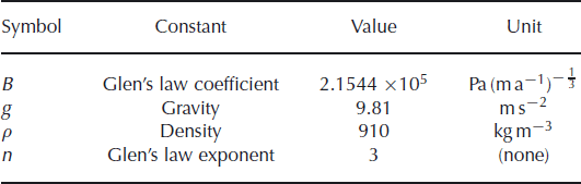
where Lx is the length of the domain. The surface is at an angle of 0.5° with the horizontal. Figure 1 shows the hybrid and BPFlow solutions for Experiment B for Lx = 10, 20, 40, 80 and 160 km. The BPFlow and hybrid solutions shown have meshes of 80 cells in the along-flow direction and 20 cells in the vertical. Surface velocities are compared with those of the ISMIP-HOM submissions that implement the first-order momentum balance (termed ‘LMLa’ according to Reference HindmarshHindmarsh, 2004). The mean over these submissions is plotted, as well as their range. In addition, the difference of velocities at depth between the hybrid and BPFlow models is shown (such information was not contained in the ISMIPHOM submissions).
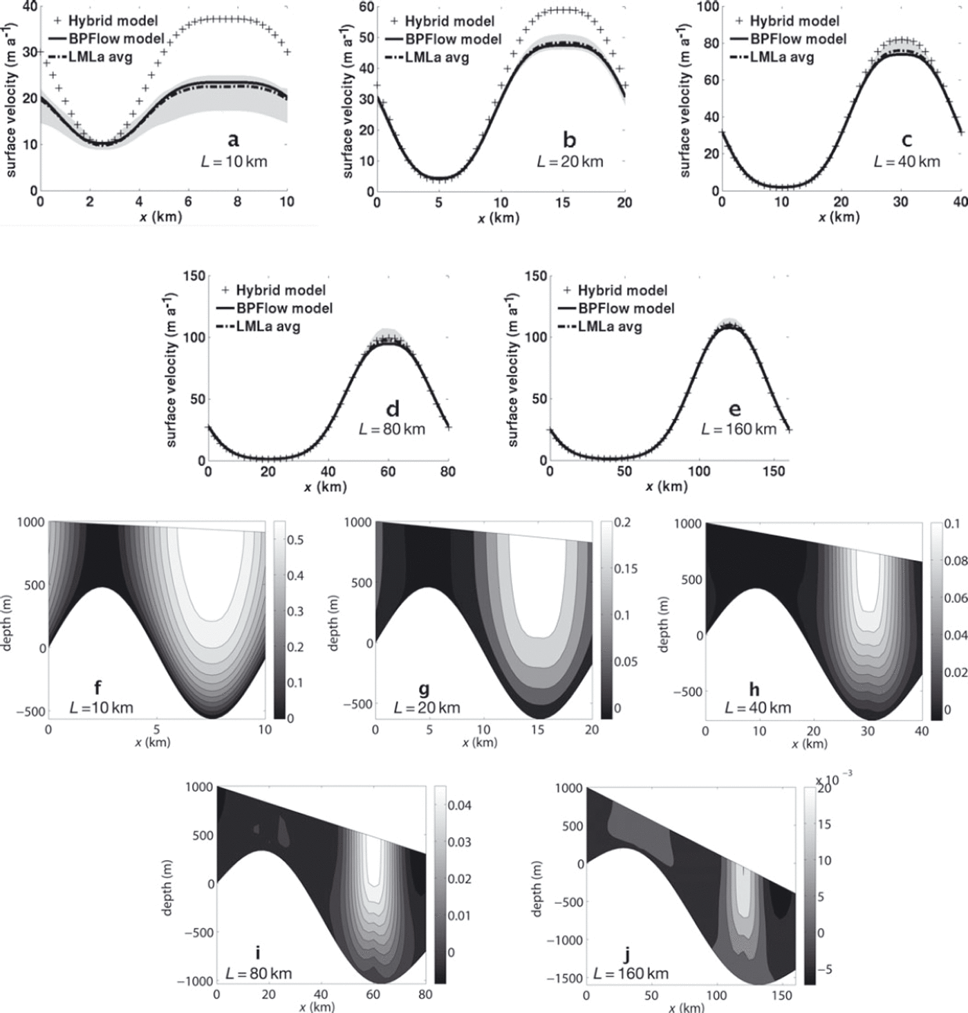
Fig. 1. ISMIP-HOM Experiment B. Flowline simulation over periodic topography. (a–e) compare surface velocities from the hybrid model with ISMIP-HOM results and with that of a first-order solver written for the purpose of this study (BPFlow). (f–j) are contour plots of velocity difference with said model at depth, normalized by the maximum surface first-order velocity (and positive where the hybrid model velocity is greater). Domain lengths are 10 km (a, f), 20 km (b, g), 40 km (c, h), 80 km (d, i) and 160 km (e, j). Note the differing scales in the contour plots.
Good agreement is seen between the BPFlow and the LMLa average. While the difference between BPFlow and the hybrid solution is substantial at short wavelengths (the solutions disagree by >50% when Lx = 10 km), disagreement is within 11% when Lx = 40 km, and <3% when Lx = 160 km. Note that the hybrid model predicts velocities too large over the topographic troughs, and the effect decreases with Lx .
For reference, the SIA surface velocity with such a surface slope and 1500 m thickness is ∼120 m a−1. This means that at Lx = 160 km, the solutions can be well approximated by SIA; i.e. longitudinal stresses are unimportant. At smaller scales, the longitudinal stresses come into play and decrease this surface velocity. Though the hybrid surface velocity is clearly too large at Lx = 10 km, horizontal stresses still clearly regulate the solution. This is explored further in the Discussion section below.
For the basal sliding experiment (ISMIP-HOM Experiment D), the thickness is held constant at 1000 m and the surface is at an angle of 0.1° with the horizontal. The basal sliding law is linear; in terms of Equation (7), this means f(u b) = β 2 u b, where the coefficient, β 2, is a scalar. In this experiment, β 2 has the spatial dependence

so that there is a ‘sticky spot’ near the left end of the domain and a nearly stress-free base toward the right, and gravitational driving stress in the latter region is mostly balanced by the transfer of basal stress from the former (through horizontal stress gradients). Figure 2 shows the results of this experiment for Lx = 10, 20, 40, 80 and 160 km. Fields plotted are the same as in Figure 1. Note from the figures on the right that while the pattern of disagreement changes with Lx , there is no strong trend in the magnitude of relative difference between the hybrid and first-order models, which is small for all length scales examined. This might be because at longer length scales, there is spatial separation between the regions where horizontal stresses dominate and those where vertical shear stresses are dominant. Regardless, at all length scales, the first-order velocity solution is very near plug flow, meaning that the hybrid momentum balance is still a good approximation. This point is explored further in the Discussion section below.
Fig. 2. ISMIP-HOM Experiment D. Flowline simulation with basal sliding with varying bed strength. Output from hybrid model is again compared with ISMIP-HOM results and BPFlow. Fields plotted are the same as in Figure 1. The pattern of velocity difference at depth seems to change for longer wavelengths. Domain lengths are 10 km (a, f), 20 km (b, g), 40 km (c, h), 80 km (d, i) and 160 km (e, j). Note the differing scales in the contour plots.
An experiment with a different sliding law is also performed. Figure 3 shows the results of an experiment similar to that of Figure 2, except that the sliding law takes the form

which can be seen as a regularized Coulomb-plastic sliding law (Reference SchoofSchoof, 2006; Reference Bueler and BrownBueler and Brown, 2009), with the yield stress, τ c, having the spatial dependence

(This profile was designed so that the yield stress does not go to zero, but can be as small as 1.5 kPa.) This was not an ISMIP-HOM experiment, so no results from the intercomparison are shown, and only the BPFlow and hybrid results are compared. These results are somewhat different than in the case with a linear sliding law, especially at short length scales. Figure 3a, which shows surface velocity when Lx = 10 km, shows a local minimum in the hybrid results that is not seen in the ‘full’ model solution. It should be noted that high along-flow resolution was necessary for these experiments in order to see the same level of convergence of the nonlinear iteration as in previous experiments, for both the hybrid and first-order models. While the previous experiments used 80 gridcells in the horizontal, these experiments used 200. For these experiments, plots are only shown for Lx = 10, 40 and 160 km.

Fig. 3. Flowline experiment with basal sliding over Coulomb-plastic bed with varying yield stress. Output from hybrid model is again compared with output of BPFlow (no ISMIP-HOM results are available). Fields plotted are the same as in Figure 1. Domain lengths are 10 km (a, d), 40 km (b, e) and 160 km (c, f).
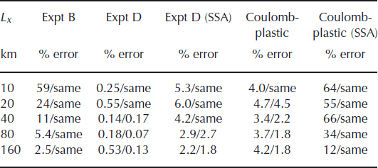
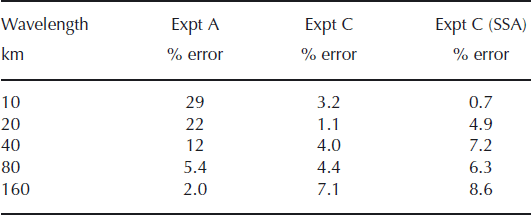
The main results of the experiments are summarized in Table 2. Percent error, defined as the maximum difference in surface velocity between the hybrid and the BPFlow model normalized by the maximum surface BPFlow velocity, is given for the above experiments at all length scales examined. Two values are given for each run; the second is the percent error when horizontal resolution is doubled (or ‘same’ if the value does not change). Also shown are the results when vertical shear effects are ‘switched off’ in the hybrid model and the balance solved is the SSA balance. Doubling the horizontal resolution does not change the percent error in the topographic experiments, nor in the short-length-scale sliding experiments, indicating that the error is a result of fundamental disagreement between the balances, and not numerical error. However, at long length scales higher resolution improves the agreement, suggesting the balances may be equivalent at those scales. Also note that SSA error in the sliding experiments, while small, is an order of magnitude larger than that of the hybrid model.
Table 2. Summary of 2-D experiments. Percent error is by comparison with the corresponding run with the in-house first-order solver (BPFlow). The second number given for each run is the value when along-flow resolution is doubled (or ‘same’ if the value does not change). SSA means the effects of vertical shear were ‘turned off’ in the hybrid model. The lower along-flow resolution for the Coulomb-plastic experiment was 200 cells, while for the others it was 80 cells
Three-dimensional experiments
For the 3-D experiments from ISMIP-HOM (Experiments A and C) a 3-D first-order solver was not created. Rather, hybrid model results are compared only with the results from submissions to the ISMIP-HOM intercomparison. In all experiments, 40 × 40 grids are used. The results of Experiment A are presented, which again involves flow over periodic topography. Again the surface slopes in the x-direction at an angle of 0.5° with the horizontal. (There is no surface slope in the y-direction.) The thickness has the form

where Lx is the length (and width) of the domain. Lateral boundary conditions are doubly periodic. Rates of convergence were similar to those seen in the corresponding flowline experiments. The results are shown in Figure 4 for Lx = 10, 20, 40, 80 and 160 km. Plotted in the figures are surface x-velocities along an x-flowline at approximately y = 0.25Lx . The ISMIP results are again averaged over all LMLa submissions, and their range is given. (These ISMIP submissions also included x-velocities along a y-transect; those figures are not shown but the patterns of agreement are similar.) It can be seen that, as in the flowline case, while the hybrid is a poor approximation at short length scales, the approximation improves at longer scales.

Fig. 4. ISMIP-HOM Experiment A: 3-D simulation over periodic topography. Plotted are along-flow velocities at the surface along a line in the along-flow direction at one-quarter of the transverse domain width. Results from the hybrid model are compared with the mean of the ISMIP-HOM LMLa submissions. The range of these submissions (shaded region) is also shown. Domain lengths (and widths) are 10 km (a, f), 20 km (b, g), 40 km (c, h), 80 km (d, i) and 160 km (e, j).
In the 3-D sliding experiment (ISMIP-HOM Experiment C), the sliding law is again linear and the parameter, β 2, has the spatial dependence

Figure 5 shows the results of this experiment. The plots are analogous to those from Experiment A, and the same length scales were examined. As with the flowline experiments, the agreement with the first-order balance at short length scales is better than in the topographic experiments. Note also that the range of the ISMIP-HOM results at longer length scales is greater than in the topographic experiments.
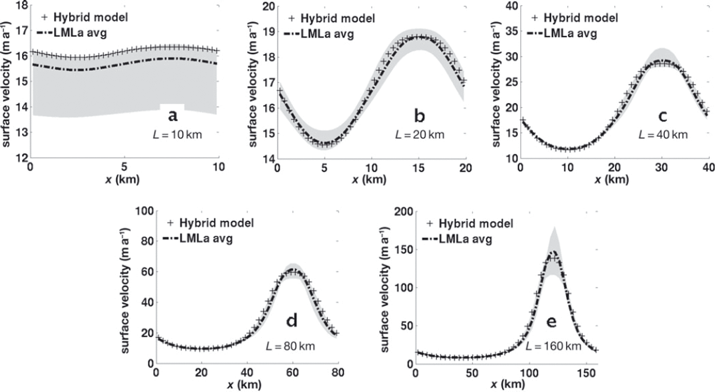
Fig. 5. ISMIP-HOM Experiment C: 3-D simulation with basal sliding with periodic traction. Results from the hybrid model are again compared with the results of the ISMIP-HOM LMLa submissions. Fields plotted are the same as in Figure 4. The range of the LMLa submissions is shown in gray. Domain lengths (and widths) are 10 km (a, f), 20 km (b, g), 40 km (c, h), 80 km (d, i) and 160 km (e, j).
In all 3-D experiments, 20 cells were used in the vertical. However, this should not be taken as indicative of the aspect ratio of vertical to horizontal resolution in an elliptic solve. Recall that the vertical mesh is for approximating the integrals in Equation (35) and diagnosing velocities at depth.
The results of these experiments are summarized in Table 3. Here percent error is assessed by comparison with the ISMIP-HOM LMLa submissions. Results are not broken down by model in the submissions, but rather the mean is taken over all submissions, so again these values should be regarded with caution. Nevertheless, it can be seen that, in the topographic experiments, agreement improves with length scale as in the flowline experiments. In the sliding experiment, the agreement is good (below 10%, and sometimes much lower) at all length scales. Again, a set of SSA experiments was also run for comparison.
Table 3. Summary of 3-D experiments. Percent error is by comparison with the ISMIP-HOM LMLa mean. 40 × 2 resolution was used in all cases
Timing performance
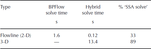
As mentioned previously, we expect the scheme for the hybrid model to be faster than a first-order solver, assuming comparable horizontal resolution. The reason is that the matrix that is inverted is smaller (by a factor of the number of gridcells in the vertical) and less dense. In the hybrid scheme this matrix has the same structure as that solved for the SSA balance. It is assumed, particularly in three dimensions, that the assembly and inversion of this matrix will be the bottleneck of the nonlinear iteration.
A timing comparison and breakdown of the hybrid scheme is shown in Table 4. The total solve times for the hybrid model and for BPFlow are given for the flowline sliding experiments (the value is averaged over all the experiments). For the 3-D sliding experiments, average solve time is given only for the hybrid model, as no first-order model was created. All experiments use 40 cells in the horizontal direction(s) and 20 cells in the vertical, and take 50 nonlinear iterations. Note the timing advantage of the flowline hybrid solver over BPFlow (roughly tenfold). Also given for the hybrid model is the percentage of the total iteration time spent assembling and solving the matrix (dubbed the ‘SSA solve’ component of the iteration), as opposed to column operations that are not part of the SSA (e.g. vertically integrating the depth-dependent viscosity). Note that for the flowline model this component takes less time than the column operations. In three dimensions, though, its relative cost is significantly higher. Also, while not done in this study, it will be far simpler to parallelize the column operations than the matrix solve.
Table 4. Timing comparison of first-order solver (BPFlow) with hybrid solve, and breakdown of hybrid solve, for flowline and 3-D experiments. Values are from averaging over all linear sliding experiments. The final column refers to the percentage of time in a single iteration spent performing the matrix assembly and solution, as in an SSA solver. All simulations had 40 cells in the x- (and y-) direction, 20 cells in the vertical and 50 nonlinear iterations
Making the individual nonlinear iterations faster, relative to a first-order scheme, is only valuable if the number of nonlinear iterations required remains roughly constant. Figure 6 compares rates of convergence between the hybrid and BPFlow models. The metric
where the norm is the sup-norm, is plotted against iteration count for ISMIP-HOM Experiment D, Lx = 40 km solves. The initial guess for both models is zero velocity, which is why the norm increases initially. It can be seen that the rates of convergence are nearly identical. Thus, provided the results of the models are similar, it can be seen that the hybrid momentum balance is a very computationally inexpensive alternative to the first-order momentum balance.
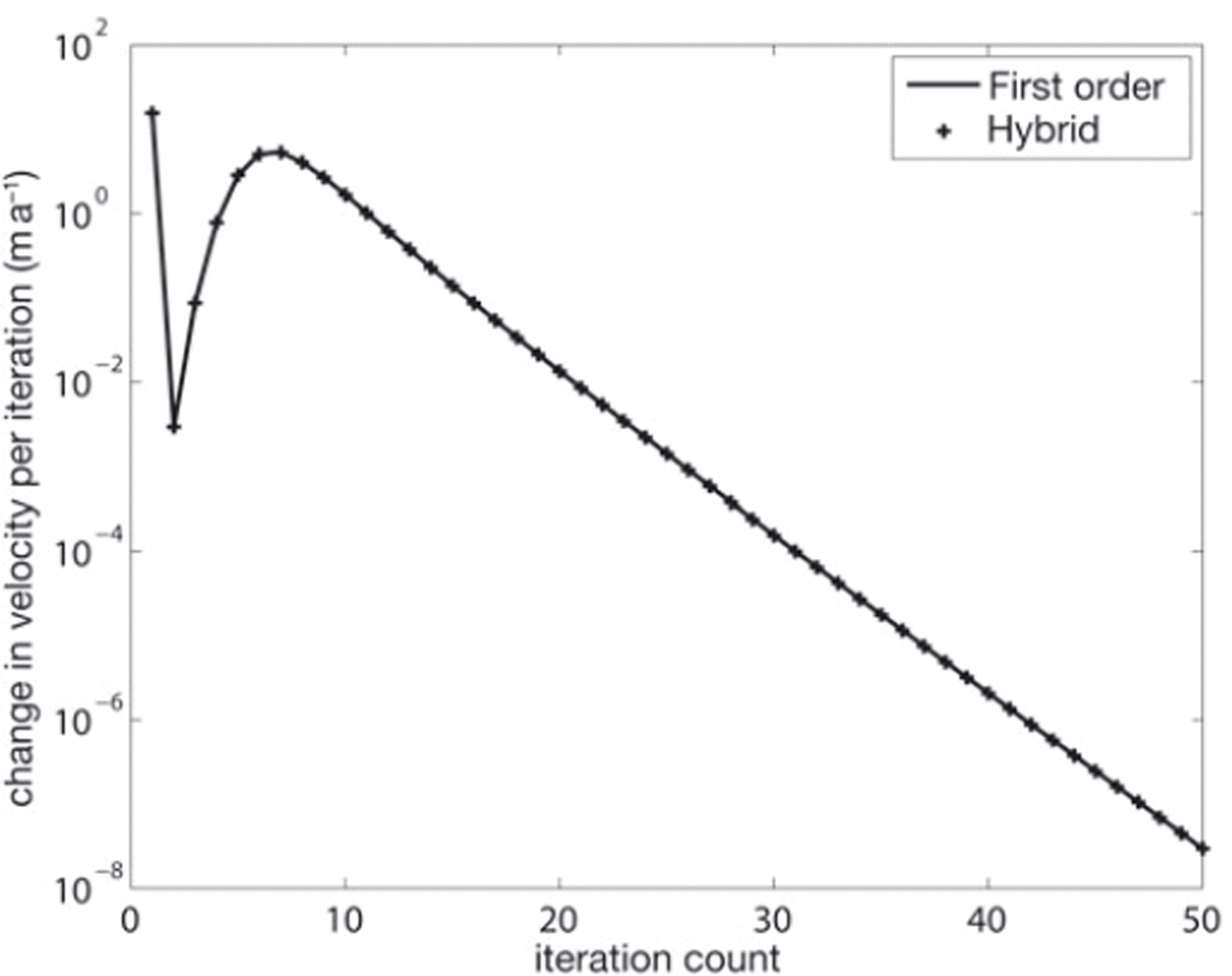
Fig. 6. A comparison of convergence rates for the hybrid model and the in-house first-order solver (BPFlow). Change in velocity per iteration is plotted against iteration count. This plot is from the sliding experiments with Lx = 40 km.
Discussion
Before discussing the results of the previous section, it is instructive to first examine the relationship between the hybrid model presented here and the depth-integrated, variationally derived model presented by Reference Schoof and HindmarshSchoof and Hindmarsh (2010; their section 4.1). Their study provides an asymptotic analysis of their model, which also applies to the hybrid model in this paper, as shown below. The behavior observed in the experiments in the previous section is then discussed in this context.
Comparison with another variationally derived model
A brief summary of the derivation of the depth-integrated model of Reference Schoof and HindmarshSchoof and Hindmarsh (2010) and their analysis is presented here for the purpose of comparison. They begin the derivation of their depth-integrated model by considering the rheology of the first-order balance in a flowline setting:
where the tensor, ![]() , is the deviatoric stress tensor. They then modify Equation (52) by replacing u with u|
z
= b
and τxz
with −ρgsx
(s − z). This approximation has an associated remainder term. The assumption that this term is uniformly small allows a depth-integrated model (their equation (4.4)), which has an associated variational principle, to be derived. The asymptotic behavior of their remainder term, and thus the accuracy of their depth-integrated model, are then investigated.
, is the deviatoric stress tensor. They then modify Equation (52) by replacing u with u|
z
= b
and τxz
with −ρgsx
(s − z). This approximation has an associated remainder term. The assumption that this term is uniformly small allows a depth-integrated model (their equation (4.4)), which has an associated variational principle, to be derived. The asymptotic behavior of their remainder term, and thus the accuracy of their depth-integrated model, are then investigated.
Proceeding analogously, Equation (52) is modified by replacing ux
by ![]() (τxz
is not replaced). This gives
(τxz
is not replaced). This gives
where
If r (hy) is assumed negligible, Equations (53) and (54) can be inverted to obtain stresses in terms of strain rates:


The first-order balance and its boundary conditions can be written in terms of ![]() :
:
By analogy with Reference Schoof and HindmarshSchoof and Hindmarsh (2010), and letting ![]() , Equation (58) is integrated in z from b to s using Equation (56), resulting in:
, Equation (58) is integrated in z from b to s using Equation (56), resulting in:
This is identical to Equations (26) and (28) in a flowline setting. Thus the hybrid model derived earlier can be obtained by assuming the remainder term, r (hy), is small.
Reference Schoof and HindmarshSchoof and Hindmarsh (2010) show that the agreement of their depth-integrated model with the first-order balance depends on the asymptotic order of their remainder term, and the same rationale can be used for the hybrid model. In their study the term corresponding to r (hy) is a sum of two terms, and the one of larger asymptotic order is (u(b) − u) x . This is a measure of the degree of velocity variation with depth, as is r (hy). And so r (hy) is of the same asymptotic order as their remainder term, and the asymptotic agreement of the hybrid model with first order (and with full Stokes) is the same as their depth-integrated model. They consider a parameter, λ, that is a scale ratio of τxz to τxx , as well as ε, the aspect ratio. In the asymptotic regime ε ≲ λ ≲ 1, which corresponds to fast sliding, their depth-integrated model is shown to agree with the first-order model with an error of O(ε 2). In the ‘slow-sliding’ regime 1 ≪ λ ∼ ε −1/n , the error is larger: O(ε 2 λn −2). Note that ‘slow-sliding’ also applies to ‘no sliding’, because λ is not infinite in this case.
Discussion of numerical results
In the flowline experiments with no-slip flow over periodic topography, it was seen that, at smaller length scales, velocity is overestimated by the hybrid model over topographic troughs. It is likely that the main reason for this is the fact that the expressions for horizontal stresses used for the viscosity (Equation (16)) are depth-independent. In Figure 7, viscosity at depth is shown for Lx = 10 km, the shortest length scale examined. (The logarithm of viscosity is what is actually shown, in order to more clearly show variability.) In both cases, there is a maximum at the surface above the trough, but in the first-order case it is considerably larger and more localized. Recall that as the second invariant of the strain rate decreases, viscosity increases (up to a maximum, determined by the regularizing coefficient used in the numerical solver). This is true for both the first-order and hybrid balances, but in the latter the longitudinal stress term in the viscosity must be constant over the entire column. In the hybrid model, the depth-averaged longitudinal stress cannot become as small as is required for this viscosity maximum at the surface. And so the viscosity maximum near the surface is less localized in the vertical as well as smaller in magnitude, giving rise to larger surface velocities.
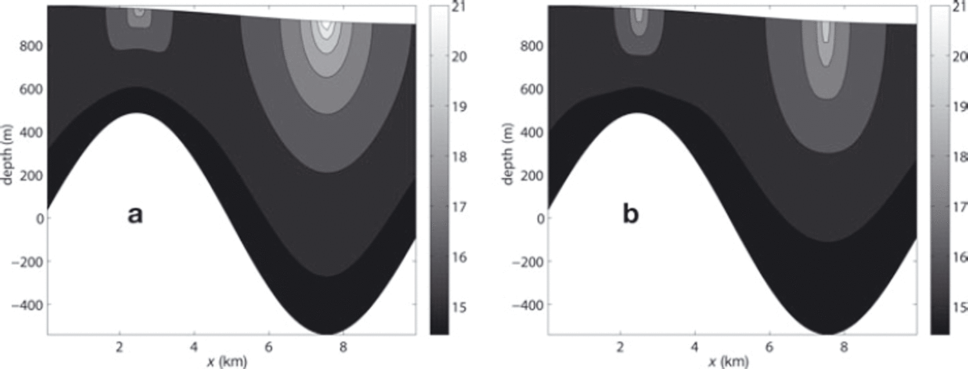
Fig. 7. Calculated viscosities (for Lx = 10 km) from (a) the in-house first-order solver (BPFlow) and (b) the hybrid model, both for flow over periodic topography. Units of viscosity are log(Pa s). (Values are plotted on a logarithmic scale so the variation can be viewed more clearly.)
The agreement of the hybrid and first-order models in the periodic topography experiments can be compared with the result of Reference Schoof and HindmarshSchoof and Hindmarsh (2010). According to their analysis, the error of approximation to the first-order balance for slow (or no) sliding is O(ε 2 λn −2). The parameter λ is calculated for these experiments and shown in Table 5, along with ε and ε −1/n . Comparison of λ with ε −1/n shows that this is indeed the ‘slow-sliding’ regime. But as shown in Figure 8, the error is closer to O(ε).
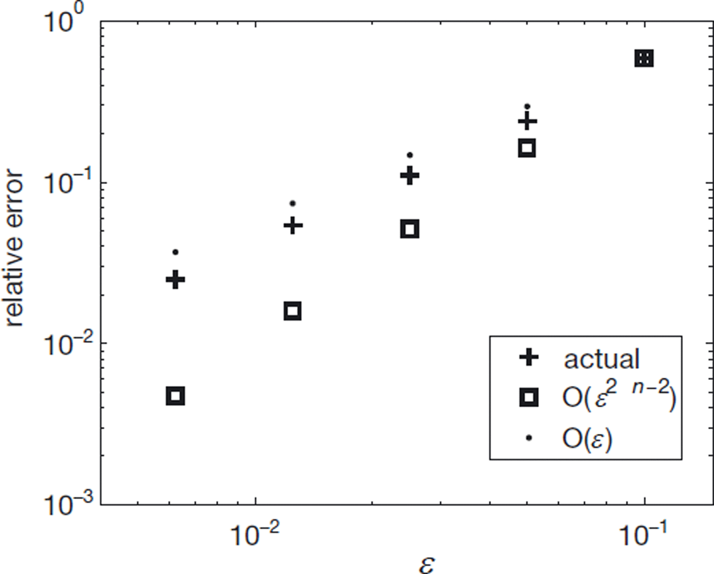
Fig. 8. Comparison of error in no-sliding experiments with that predicted by Reference Schoof and HindmarshSchoof and Hindmarsh (2010) (O(ε 2 λn −2)) and with first-order (O(ε)) error. ε is the aspect ratio and λ is a parameter related to the slip ratio.
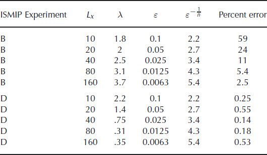
Table 5. Nondimensional parameters, ε (H/L) and λ, of the first-order solution in the flowline experiments. λ is a scale ratio of τxz to τxx . The scales of τxx and τxz were taken to be the largest values in the numerical solutions. Experiment B is no-slip flow over periodic topography and Experiment D is sliding flow with periodic basal traction. Percent error of the hybrid approximation is shown again for convenience
In the flowline experiments with sliding flow over periodic basal traction, the error of approximation with first order was uniformly small. The asymptotic analysis of Reference Schoof and HindmarshSchoof and Hindmarsh (2010) discussed above predicts good agreement in the fast-sliding regime, ε ≲ λ ≲ 1. This regime applies to these experiments, as seen from Table 5. However, the results of the analysis do not imply, a priori, that the agreement will be equally good at both large and small length scales. Rather, if the remainder term, r(hy), is examined, a posteriori, from the results of the first-order solver, BPFlow, we can see why the hybrid model is able to approximate first order so closely at small length scales. Figure 9 shows the deviation of velocity from its vertical mean along the flowline in the 10 and 160 km first-order solutions. It is not more than 7%. Examination of the velocity at depth in the 10 km experiment (not shown here) shows that the expression of variations in basal traction at the surface is very small, with most of the along-flow velocity variation very close to the base. Since r(hy) is small when ![]() is small, this suggests that the hybrid model is a very good approximation to first order at short length scales as well as long ones, where ε is small.
is small, this suggests that the hybrid model is a very good approximation to first order at short length scales as well as long ones, where ε is small.
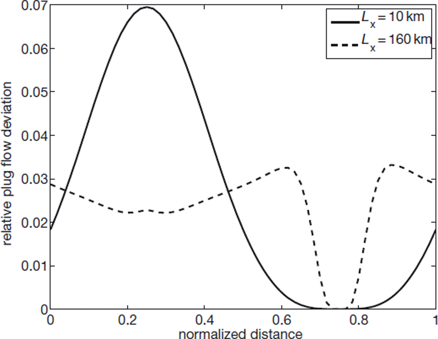
Fig. 9. Deviation of u from plug flow in the sliding experiments with the first-order solver (BPFlow). Values plotted are the maximum within a column of ![]() normalized by
normalized by ![]() . Distance is normalized by Lx
.
. Distance is normalized by Lx
.
Conclusion
A set of momentum balance equations for large-scale motion of ice sheets has been derived that approximates the first-order momentum equations. The balance was derived not by making approximations to the equations and boundary conditions directly, but rather by making approximations to a nonlinear functional from which the first-order momentum balance arises, and then using variational methods to derive the new set of equations. The balance treats horizontal stresses as depth-integrated, but includes the effect of nonzero vertical shearing strain rates on the nonlinear viscosity and the sliding law, and is termed a ‘hybrid’ model in this study. A numerical scheme was developed and implemented to solve the equations by means of ‘iterationon-viscosity’, which involves the solution of a 2-D (rather than a 3-D) elliptic equation when solving for 3-D flow, and a 1-D (rather than 2-D) equation when using a flowline model. This yields a significant computational advantage over the first-order balance in terms of the matrix inversion at each nonlinear iteration. Further, experiments with flowline models showed that the number of nonlinear iterations required to obtain a certain level of accuracy does not increase relative to a first-order solver.
Comparison of surface velocity output both with a flowline first-order solver written specifically for this study and with the results of the ISMIP-HOM intercomparison was encouraging, showing good agreement of the hybrid model output with the first-order solutions over a wide range of spatial forcing scales. In the experiments involving ice frozen to the bed and flowing over rough topography, agreement is poor at very short scales (10–20 km), but improves at longer scales. Comparison of stress terms at depth with the flowline first-order solver written for this study indicates that this is because longitudinal strain rates can become highly depth-dependent in such a setting, something not allowed for by the hybrid set of equations. The error is approximately first-order in the aspect ratio, which is slightly larger than that predicted by the asymptotic analysis of Reference Schoof and HindmarshSchoof and Hindmarsh (2010).
The hybrid balance is therefore a potentially powerful tool for large-scale ice-sheet modeling, especially when looking at domains that are expected to contain fast-flowing ice streams and shelves, as well as slow-moving ice that is frozen to its bed. The similarity of its depth-integrated form to the SSA balance means that a model that solves the SSA balance could be modified to solve the hybrid balance without considerable effort.
Acknowledgements
The author acknowledges the careful and insightful reviews of R. Hindmarsh, S. Price, J. Dukowicz and scientific editor C. Schoof. Additionally, O. Sergienko and D. Pollard gave helpful and insightful comments on earlier versions. This work was supported by a Princeton AOS/GFDL fellowship.


