


Introduction
The ability to visualize biological samples such as purified proteins or cellular organisms in a near-native state is the hallmark of cryogenic electron microscopy (cryo-EM). This technique, popularized over the past 20 years, culminated in its recognition by Nature in 2015 and 2016 [single particle analysis (SPA), cryo-EM, 2016; cryo-electron tomography (cryo-ET), Doerr, Reference Doerr2017] and the Nobel Prize in Chemistry in 2017 (Press release, 2017). Cryo-EM was once thought to be available to only a subset of highly specialized laboratories that were able to prepare samples, collect the data, and provide the proper analysis to answer a specific biology question. However, in recent years, more and more laboratories are utilizing this technique, mainly due to the creation of regional and national facilities with experienced staff that help with the steps in the process (Stuart et al., Reference Stuart, Subramaniam and Abrescia2016; Alewijnse et al., Reference Alewijnse, Ashton, Chambers, Chen, Cheng, Ebrahim, Eng, Hagen, Koster, Lopez, Lukoyanova, Ortega, Renault, Reyntjens, Rice, Scapin, Schrijver, Siebert, Stagg, Grum-Tokars, Wright, Wu, Yu, Zhou, Carragher and Potter2017).
The sample preparation step is a key factor for successful cryo-EM experiments, and a growing arsenal of freezing devices is now available. The three most cited automated devices include the Thermo Fisher Scientific (TFS) Vitrobot, the Leica Microsystems EM GP/GP2, and the Gatan Cryoplunge 3 System. Each provides the user with a semi-automated and reproducible process for plunge freezing samples, including temperature and humidity control, adjustable blotting times, and plunging. The user remains responsible for loading the tweezers that hold the grid, applying the sample to the grid, and transferring the vitrified sample to a storage container. The next generation of automated plungers is now entering the market, offering improvements to the sample application and blotting steps, incorporating glow discharging of the grids, automated application of the sample, and/or a variety of other features (e.g., see Dandey et al., Reference Dandey, Wei, Zhang, Tan, Acharya, Eng, Rice, Kahn, Potter and Carragher2018; Rubinstein et al., Reference Rubinstein, Guo, Ripstein, Haydaroglu, Au, Yip, Di Triani, Benlekbir and Kwok2019). However, all these instruments are large, immobile, and/or expensive.
Even research groups who use cryo-EM as the primary technique may encounter problems in sample preparation when the sample cannot be transported to a fully equipped cryo-EM laboratory. This is the case, for example, when the biological samples need to be cultivated in other laboratories under highly specialized conditions or for biosafety reasons. In such cases, it is often advisable or required that the specimen be prepared on site at the collaborating laboratory.
Because of our own need to prepare samples abroad, our laboratory decided to embark on building a portable manual cryo-plunger (PMCP). The goal was to return to a simple, cost-effective, and sturdily designed instrument that can be easily transported between laboratories. With this device, the local/onsite items required for the plunge freezing step are liquid nitrogen for cooling the device and storage of the frozen samples, a cryogen (typically ethane) to freeze the sample, and the sample itself. Everything else can be transported with the device, including the container (a dry shipper) to ship the frozen samples back to the laboratory for processing. Onsite convenience items would be a screening microscope, such as a 120 kV transmission electron microscope (TEM) capable of evaluating the quality of the cryogenic samples to optimize sample preparation conditions and a glow discharge unit to negatively charge the grids. For the former item, this is not necessary if the group has a significant experience with a similar sample type, has access to a similar sample to optimize preparation in a cryo-EM laboratory, or a combination of both. For the latter, grids can be discharged prior to travel, but the user should determine how long the hydrophilicity will last for each specific combination of the grid type and sample buffer prior to travel.
We based our design on a published device designed to freeze samples in the field (Comolli et al., Reference Comolli, Duarte, Baum, Luef, Downing, Larson, Csencsits and Banfield2012). We used their designs as a guide for the development of our PMCP. Specifically, we adjusted the total height of the plunger and redesigned the liquid nitrogen container and insert that holds the cryogen container and the grid boxes. In addition, we added several new features, including a submerged storage space for temporary storage of filled grid boxes, the replacement of the single pole between the top and bottom plates with three adjustable rods that allow for precise centering of the tweezers, a more robust polycarbonate shielding surrounding the plunging chamber, and a baseplate that can be clamped to a counter top or surface to provide additional stability.
We tested our PMCP by plunge freezing samples of the bacterium, Vibrio cholerae, and evaluated the quality of the vitreous ice and cells to determine if the samples were suitable for cryo-ET. To demonstrate that the PMCP is equally capable for the specimen preparation of protein complexes for SPA, we also tested the performance of our device with equine apoferritin (molecular weight 443 kDa), a protein complex regularly used as a reference standard for SPA. The updated design was successful in plunge freezing both bacteria and protein complexes, producing thin, vitrified ice that is suitable for imaging with a TEM. This design will expand access to cryo-EM by promoting collaboration among cryo-EM and noncryo-EM laboratories and also invites laboratories that want to include cryo-EM in their research techniques for understanding the biological world without the need to purchase expensive commercial equipment.
Materials and Methods
Design and Engineering of a Manual Portable Cryo-Plunger
To begin, we obtained the original designs to the instrument described by Comolli et al. (Reference Comolli, Duarte, Baum, Luef, Downing, Larson, Csencsits and Banfield2012). However, we sought to optimize the design for our specific needs to travel extensively with the instrument and reduce the overall production cost. The final design schematics are outlined in Figure 1, and representative images of the final device are presented in Figure 2. A table of approximate costs can be found in Supplementary Table 1. Our first major change was to reduce the total height of the instrument by 150 mm to create a more portable footprint (Figs. 1a–1c, 2a–2c). This was accomplished by reducing the height of the plunging arm and enclosure. We retained the spring-loaded, piston-based, plunging arm from the original design, as this provides the necessary drop speed to minimize evaporation and ensure vitrification of biological samples. However, we found it necessary to add sorbothane (a hard rubber polymer) rings to provide dampening of the tweezers at the end of the fall.
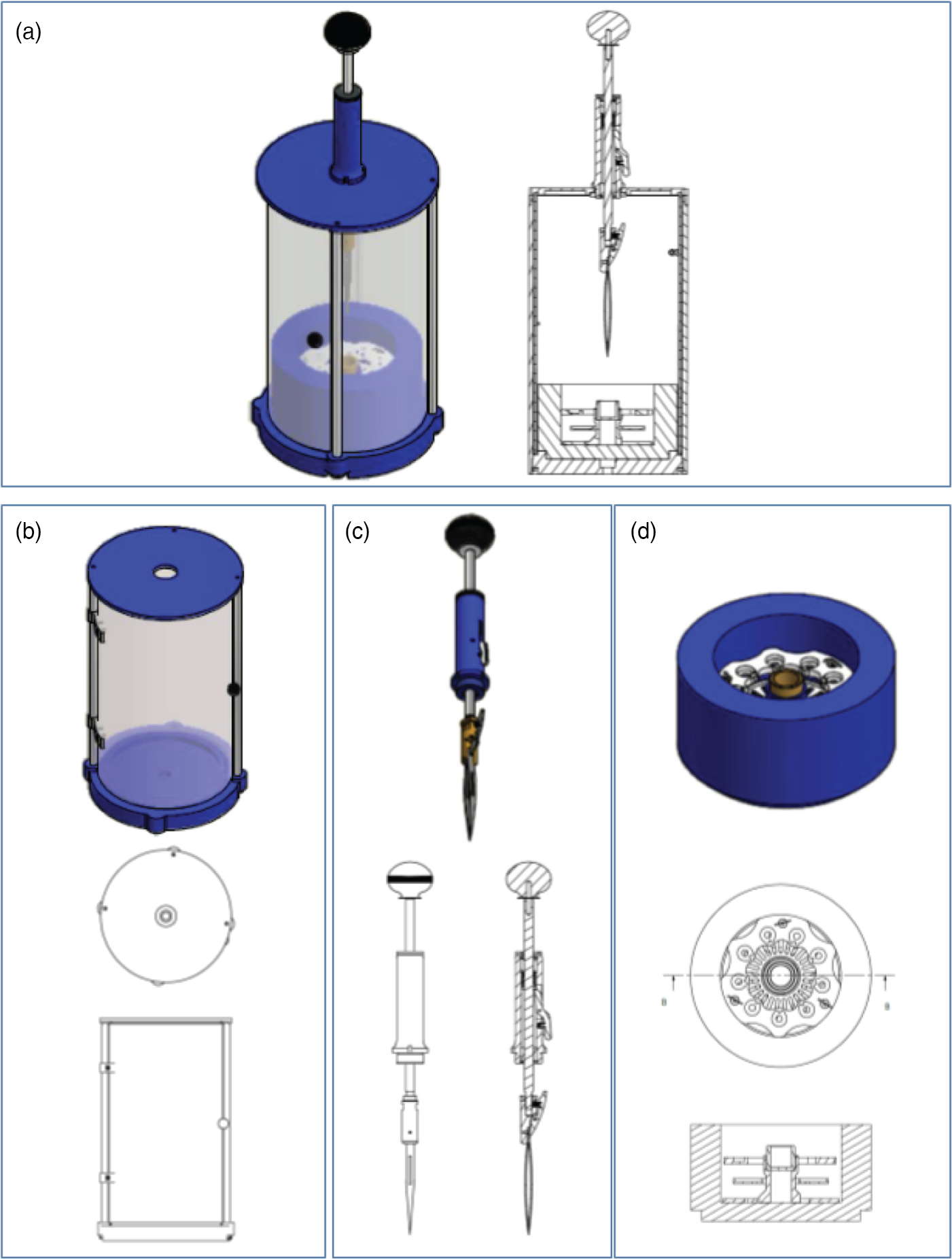
Fig. 1. Schematic overview for the components of the PMCP freezer. (a) The assembled PMCP. (b) The body of the PMCP with the top separate because of the need to incorporate the plunging arm and highlighting the door access to the sample area. (c) The spring-loaded plunging arm (spring contained within the blue cylinder) with release lever and tweezers. (d) The cryogen container, which contains three components: the dewar for liquid nitrogen (blue), the grid box storage insert (white), and the cryogen container (gold). Detailed designs are available from https://briegel-lab.org.
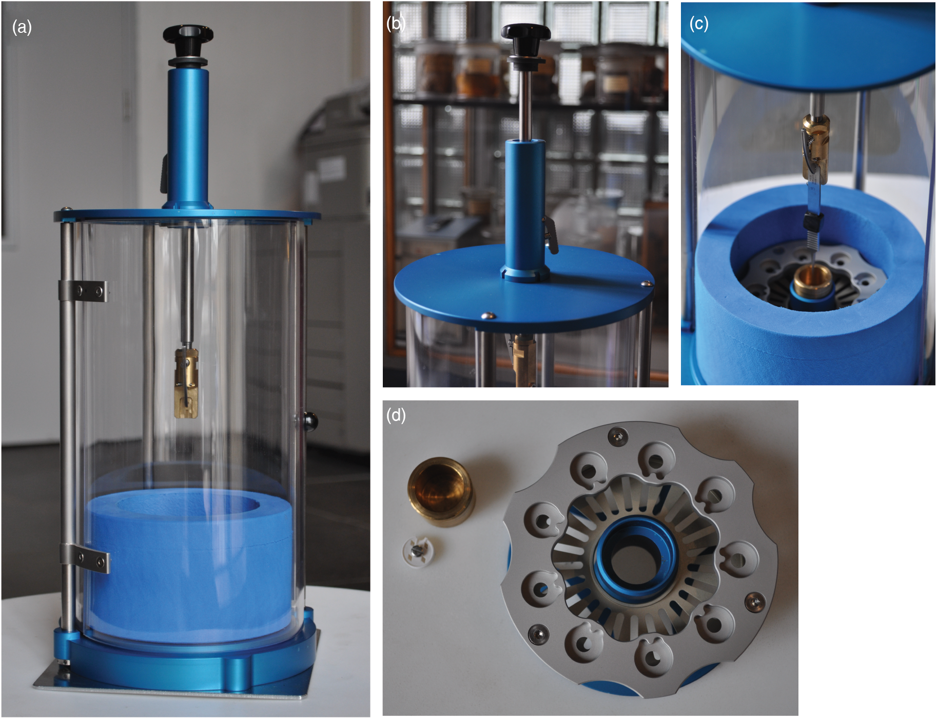
Fig. 2. Photographs highlighting different aspects of the PMCP. (a) The assembled PMCP with the plunging arm in the unloading/transport position, shielding door closed, and sitting on the stability plate. (b) The plunging arm in the loaded position, highlighting the release lever of the spring-based plunging mechanism. (c) The position of the tweezers following a press of the release lever, with the tweezers landing in the cryogen cup (gold) of the assembled cryogen container (blue/silver). (d) Top view of the grid box holder (silver/blue), cryogen container (gold), and representative grid box (white) for comparison.
Next, we replaced the Vitrobot-based cryogen vessel, grid box holder, and liquid nitrogen container (originally from TFS) with a less expensive, combination of commercially available and locally built alternatives (Figs. 1d, 2c, 2d). For the liquid nitrogen container, we chose a lightweight foam cryogenic container (Figs. 2a, 2c; Spearlabs Cryogenic Products). The dewar was customized to fit the base of the plunger. Instead of the “spider design” of the Vitrobot heat exchanger, we incorporated the grid box and a cryogen container holder into a single piece of aluminum (Fig. 2d). As a result, there was no need for multiple parts, while still maintaining the ability to remove the cryogen container from the device at the end of the plunge freezing (which allows for safe evaporation of the cryogen). Furthermore, an extra deep shelf was added to the insert so that the filled grid boxes can be stored completely covered in liquid nitrogen to prevent warming and ice contamination of the samples during lengthy freezing sessions (Figs. 1d, 2c, 2d).
We next decided to improve the stability of the plunger by exchanging the single arm attaching the top and bottom with three adjustable legs, as well as to increase sample protection around the plunger and to add a supporting plate to the bottom of the device (Fig. 2a). The three adjustable legs also allow the user to accurately center the tweezers with respect to the cryogen container. The shield surrounding the device is more user-friendly, as it includes a hinged door and it is made from a more robust polycarbonate material. The plate can be additionally secured by clamping it to the benchtop, increasing the overall stability of the instrument during freezing. As with the original design, the connection used to attach the plate can also be used to attach the device to a tripod for use in the field.
Lastly, we wanted the device to accommodate the same tweezers (Dumont medical tweezers, clamp style L5) that are used in the commercial devices so that we could exchange the tweezers between the instruments. We adapted the tweezers by drilling a hole in the handle, which is then used to secure the tweezers to the plunger arm.
Once the dimensions of the prototype were finalized, we ordered a custom, padded box to store and transport the instrument (Swanflight.com). We included a separate shelf that allowed for storage of two segmented boxes (Raaco) used for items, such as the tweezers, grid boxes (Molecular Dimensions, UK), and precut pieces of filter paper (Whatman 1) used for manual blotting. The second box is used for spare parts such as additional plunging tweezers, tweezers for transferring the grid boxes, and screwdrivers for tightening the lids of grid boxes.
Testing the Design and Improving the Design
Once we were satisfied with the design, we moved forward with testing of the PMCP. We started with the vitrification of a commonly used bacterium, V. cholerae. This curved bacterium is a frequently used sample in cryo-EM studies, as it is naturally thin (ranging from 0.25 to 0.5 µm in diameter and 1–2 µm in length), and it is easily imaged with a screening TEM microscope. In addition, the bacterium has many identifiable features that are apparent in well-prepared samples, such as chemoreceptor arrays, type VI secretion systems, and the flagellar apparatus (Chen et al., Reference Chen, Beeby, Murphy, Leadbetter, Hendrixson, Briegel, Li, Shi, Tocheva, Muller, Dobro and Jensen2011; Briegel et al., Reference Briegel, Ladinsky, Oikonomou, Jones, Harris, Fowler, Chang, Thompson, Armitage and Jensen2014; Wang et al., Reference Wang, Brackmann, Castaño-Díez, Kudryashev, Goldie, Maier, Stahlberg and Basler2017).
A typical plunge freezing workflow is as follows: the preparation of the sample to obtain an appropriate concentration in a compatible buffer ready to be pipetted onto the EM grid, cooling of the instrument and cryogen, the application of the sample to a glow discharged grid, incubation, blotting away excess liquid, and plunging the sample loaded grid into the cryogen. Thus, we used a similar process for the PMCP (Supplementary Movie 1). Our sample preparation protocol was to grow a freshly streaked culture of wild-type V. cholerae strain A1552 in liquid LB medium overnight at 30°C with shaking at 180 rpm. Once the culture was at an OD600 > 1.3 (typically 12–16 h), 20 µL culture was mixed with 1 µL of 15 nm protein A-treated gold beads (Cell Microscopy Core, Utrecht University, Utrecht, The Netherlands) to produce the sample for freezing. 3 µL of the sample was applied to a glow discharged (25 mA for 60 s, Quorum Q150RS, Electron Microscopy Services) Quantifoil R2/2 Cu 200 mesh grid with extra thick carbon (Quantifoil Micro Tools, GmbH), followed by manual blotting. With manual blotting, it is important to have sufficient lighting to judge the rate of liquid removal. We positioned a light source directly behind the sample to monitor the blotting. Once the liquid halo on the blotting paper stopped spreading, the blot paper was withdrawn within 1 or 2 s, and the lever was immediately depressed causing the sample to drop into the liquid ethane. Vitrified samples were transferred into grid boxes for storage until imaging. A movie demonstrating the blotting process under dry conditions can be found in Supplementary Movie 2.
For the SPA sample, equine apoferritin (Sigma) was diluted into gel filtration buffer [50 mM HEPES (pH 7.5), 150 nM NaCl, 2 mM DTT] and injected onto a Superdex 200 Increase (3.2/300) gel filtration column that was pre-equilibrated in gel filtration buffer. Peak fractions were collected with an OD280 of 1.7, corresponding to a concentration of 2.3 mg/mL. Following purification, 3 µL of the protein sample was applied to a glow discharged Quantifoil R2/2 Cu 200 mesh grid, excess liquid was removed by manual blotting, and the sample was immediately plunge frozen.
For sample screening, we used a Talos L120C (TFS) side entry electron microscope with extended cooling capacity. Samples were inserted into the microscope using a Gatan 626 side entry holder, and images were acquired with a Ceta CMOS camera. For the tomography sample, nominal magnification ranged from 1,200× to 22,000×, corresponding to a pixel size of 7.97–0.465 nm/pixel (FOV 31.88–1.947 µm2), respectively. At the highest magnification, defocus used for imaging was −6 µm. For the SPA sample, nominal magnifications used for screening ranged from 380× to 92,000×, corresponding to a pixel size of 26.4–0.111 nm/pixel (FOV 105–0.444 µm2), respectively. The apoferritin sample was imaged with settings similar to those that would be used on a Titan Krios: a total dose of 40–50 e−/A, defocus of −2 µm, and a pixel size of 1.1 Å/pixel.
Results
Figure 3 provides representative images from our sample testing of the PMCP. For these samples, we repeated the standard protocol that we used with our automated plunger but substituted automated blotting for manual blotting as described. For the bacterial sample (Figs. 3a–3c), the ice was clearly vitreous, as demonstrated by a consistent, visually smooth layer across most parts of the grid. On occasion, contamination did occur either from crystalline water or residual frozen ethane. However, most grids had sufficient, similar areas for imaging, and they compared well to our grids prepared by the automated plunger. A progressive zoom in series on the sample supports these conclusions (Fig. 3).

Fig. 3. Representative images demonstrating the quality of samples prepared using the PMCP by imaging with a 120 kV TEM. V. cholerae sample shows quality of vitrious ice (a-c), the distribution of cells (a) and 15 nm gold beads (b,c), and an example of a single cell suitable for cryo-ET. The chromatography-purified equine apoferritin sample shows the quality of vitreous ice at low (d) and mediate (e) magnifications and the particle distribution (f). (c) and (e) were imaged with a defocus of −6 and −2 μm, respectively.
We next demonstrated that the PMCP was suitable for preparing samples for SPA. For this, we used a sample that is well known in the single particle community, apoferritin. Many adjacent squares on the grid have an ideal area of vitreous ice within the square. Here, the edge of a square's corners appear round, and the edges of the hole on the supporting film are clearly visible (Fig. 3d). A zoom-in within a square shows that the ice thinning within the hole is homogenous, which shows as a concentric gradient in the background intensity from the edge to the center in all holes in the view (Fig. 3e). The thin region in the center of the hole provides a sufficiently large field of view for high magnification imaging of the particles, which appear evenly distributed without excessive contaminants (Fig. 3f). The thin ice also provides good contrast while preserving the sample, providing the necessary balance that is critical for successful SPA projects.
Discussion
Building on the published work, we have optimized the design of a previously reported manual plunger, and we demonstrated that it can prepare samples suitable for both cryo-ET and SPA. With our device, we successfully vitrified samples of V. cholerae and apoferritin. Detailed designs are freely available to the academic community, with the hopes of enabling, in cryo-EM laboratories, the flexibility to prepare samples anywhere, or, for non-cryo-EM laboratories, to incorporate this technique into their experimental toolbox at a low cost. We see this as an important step in the larger community goal of democratizing cryo-EM (Hand, Reference Hand2020).
During the course of the design, we encountered several challenges. First, we found that the ethane level in the cryogen container directly impacted the amount of residual ethane on the grid after freezing. Though this was not a significant issue because it can be evaporated off or physically removed before imaging, some ethane contamination can sometimes be seen on the grids. Our initial path to resolving this issue was to allow the ethane to evaporate by holding the grid just above the liquid nitrogen layer for several seconds (duration depended on the thickness of ethane) before transferring to a grid box for storage. Alternatively, a piece of filter paper was cooled and suspended just above the liquid nitrogen level allowing the excess ethane to be wicked away by carefully side blotting after plunging. This issue became most prevalent following the melting of the frozen ethane using ethane gas, which subsequently increases the total volume of ethane, and causes the tweezers to also retain some liquid ethane. Being very near the freezing point of ethane, which is ideal for sample preservation, also makes the ethane more viscous. This led us to change our method of thawing the frozen ethane. Instead of introducing additional gaseous ethane during the freezing session, we used a thick metal object such as the back end of a clean tweezer or scalpel handle to melt the ethane. Either technique allows liquid ethane in the cryogen holder to maintain a suitable temperature range for generating vitreous samples but reduces excess ethane being retained by the tweezers or spilling over into the cryogen container. One additional option to avoid issues with contaminating ethane is the use of an ethane/propane mix instead of pure ethane, as the mix remains liquid at liquid nitrogen temperatures (Tivol et al., Reference Tivol, Briegel and Jensen2008).
A known challenge inherent to manual plunging is how to precisely and reproducibly control how much sample is wicked off from the grid. Thus, we provide a video demonstrating the process as a supplement (Supplementary Movie 2). Typically, this experience depends on an accumulated practice on a trial-and-error base. To assist the development of some visual assessment of the blotting process, we placed a light source positioned directly behind the grid. The additional lighting allowed for better monitoring of the wicking and easier determination when blotting was optimal. Additionally, a careful retraction of the blotting paper prevents the breaking of the carbon layer on the grid. For the entire blotting procedure, practice was the best method for obtaining suitable, reproducible samples.
Another issue that could present itself is identifying a local site for glow discharging the support grid. This is critical because carbon-coated grids are hydrophobic and thus when an aqueous sample is applied, the liquid will not distribute evenly across the grid. Glow discharging allows one to create a negatively charged surface that is more suitable for aqueous samples. In our hands, using the grid type and glow discharge protocol noted in the methods, we have had a sufficient number of squares with suitable ice thickness from grids that were several days post discharge. Thus, if it is not possible to glow discharge grids on site, then doing so prior to departure, may be a successful alternative. Here, the accumulated experience for judging when optimal wicking has occurred makes adjusting for slightly different hydrophilicities straightforward.
Lastly, our initial goal was to build a device that could be easily transported and conform to airline restrictions for cabin luggage. While the device itself is quite portable, the case that was made for the final design turned out to be slightly bigger than the standard overhead compartment in an airplane. This challenge could be overcome by a significant reduction in the diameter of the instrument and carrying case, but this may come at a cost of its performance, its stability, and unhindered working space. This should be a goal for future iterations. In addition, certain items are restricted from carry-on luggage, such as the sharp tweezers, scissors, and any of the required gases, which would prevent the device being placed in the overhead bin.
In this communication, we share the designs for an economical, portable manual cryogenic plunger device that allows for the proper freezing of samples for cryo-ET and SPA. In addition to being able to prepare multiple sample types, this device is quite portable enabling the preparation of samples at sites generally not equipped specifically for cryo-EM. Our hope is that this device will expand this technique well beyond the local experts and contribute to the basic understanding of the microscopic biological world.
Supplementary material
To view supplementary material for this article, please visit https://doi.org/10.1017/S1431927620001385.
Acknowledgments
We are grateful to Melanie Blokesch for providing the V. cholerae A1552 strain, to Meindert Lamers for providing the purified apoferritin, and to Stuart Howes for valuable feedback. This work was funded by the Building Blocks of Life Grant 737.016.004 (Briegel) from the Netherlands Organization for Scientific Research.


 Open access