


Introduction
Multiband antennas are designed to operate over a wide range of frequencies. They are often used in applications where it is necessary to communicate on several frequency bands, such as in a cellular or satellite mobile communication system. Multiband antennas also allow the communication system to support various standards, which can differ from country to country.
Many microstrip and coplanar waveguide multiband antennas are developed in the literature to include different standards in one patch. Some antennas are designed to include both 2.4 and 5 GHz WLAN (wireless local area network) and WiMAX (Worldwide Interoperability for Microwave Access) communications [Reference Song, Jiao, Zhao and Zhang1]. Some have been specially designed for mobile devices to support GSM (Global System for Mobile Communications), LTE (Long-Term Evolution), and UMTS (Universal Mobile Telecommunications System) cellular protocols in addition to WLAN/WiMAX bands [Reference Cui, Yang, Liu and Li2]. We can also develop others for Internet of Things (IoT) applications, including WLAN, WiMAX, and C-band communications [Reference Singh, Goswami, Sharma and Goswami3].
Multiband antennas can be designed using many different techniques [Reference Gao, Luo and Zhu4]. The multilayer PIFA (planar inverted-F antenna) configuration is often used for cellular mobiles to achieve multiband operation in the ISM (Industrial, Scientific, and Medical) band [Reference Byndas, Hossa, Bialkowski and Kabacik5]. Another promising technique is based on the use of frequency selective surface to provide selectivity in the frequency response of the antenna [Reference Fernandes, da Silva, da Silva Briggs, de Siqueira Campos, de Araújo, Casella, Capovilla, Souza and de Matos6]. We can also mention the metamaterials, which can be used for this purpose [Reference Christydass and Gunavathi7, Reference Rajkumar and Usha Kiran8].
Another alternative that has caught the attention of researchers is that based on fractal geometries because of its self-similarity and space-filling properties [Reference Karmakar9]. Self-similarity is to multiplying the copies of the original shape with different scaling factors and space-filling consists of diminishing the antenna size. Concerning this fractal technique, the antenna can operate on multiple frequencies by resolving the spacing problem [Reference Bhatia and Singh Sivia10]. Many articles have been published in this context. In paper [Reference Liu, Liang and Zhensen11], the tree-like fractal structure is used for a dual-band microstrip RFID (radio Frequency identification) antenna. In [Reference Yadav, Jain, Osman Sid Ahmed, Saad Hamad, Dhiman and Alotaibi12] Koch curve fractal is used for IoT (radio frequency identification) applications, while the Minkowski fractal is used in paper [Reference Rengasamy, Dhanasekaran, Chakraborty and Ponnan13] for WLAN/WiMAX communications. We can also cite the Hilbert curve fractal employed in paper [Reference Alibakhshi‐Kenari, Naser‐Moghadasi, Ali Sadeghzadeh, Virdee and Limiti14] for designing a dual-band RFID tag antenna for high frequency and ultra-high frequency applications. Further, the Koch snowflake fractal is employed in paper [Reference Sivasundarapandian and Suriyakala15] for a planar multiband antenna for cognitive radio.
In this work, we propose to design multiband antennas for 5 GHz WLAN communications. The full 5 GHz WLAN range covers frequencies from 5.15 to 5.85 GHz. It can be used in IEEE 802.11 a & n. The 5 GHz WLAN band is divided into three sub-bands named respectively UNII-1, UNII-2A, UNII-2C, and UNII-3, and the future bands UNII-2B and UNII-4 [Reference Moradi-Pari and Miucic16]. The 5 GHz band offers significantly more bandwidth than the 2.4 GHz band. All 5 GHz channels offered, support a channel width of at least 20 MHz without overlap and it can achieve 160 MHz of width.
To meet these specifications, Minkowski fractal geometries are combined with genetic algorithms (GAs). The Minkowski iteration will be used as chromosomes, resulting in a non-uniform fractal antenna, and allowing control over the allowed bands. For the Minkowski Island fractal, the initiator is a Euclidean square.
A GA is a heuristic optimization method inspired by the process of natural selection in biology [Reference Haupt and Ellen Haupt17]. A set of individuals, also called an initial population, is built from the chains of chromosomes or genes, coded in binary (0 and 1). The GA then uses different operators, such as selection, crossing, and mutation to evolve the population of individuals over several generations until convergence toward the optimal individual carrying the chromosomes/genes meeting the optimization goals. In recent years, the GA has become a very powerful optimizing tool in the field of antenna design [Reference Gulati, Siddharth, Vedi and Susila18]. Questions of miniaturization [Reference Lamsalli, El Hamichi, Boussouis, Touhami and Elhamadi19] and improved gain [Reference Kanni and Brinda20] were explored using this technique, in addition to addressing the challenges associated with optimizing multiband antennas [Reference Jayasinghe21, Reference Pérez‐Moroyoqui, Rodríguez‐Romo and Ibáñez‐Orozco22].
For the present optimization problem, the chromosomes will be the three-iteration Minkowski fractal generators. The GA will generate an initial population of antennas by a random set of chromosomes. This process will provide a wide range of possible configurations, unlike a standard fractal antenna, allowing for greater diversity and increasing the likelihood of having multiband antennas on the desired bands. The resulting antennas are therefore non-uniform fractals, three Minkowski generators coexist in the same individual.
To apply the GA operators, we will need to evaluate the individuals (antennas) at each generation. To meet this requirement, CST’s (Computer Simulation Technology) internal FDTD (Finite-Difference Time-Domain)-solver is used and automated from MATLAB. This process can take hours or even days if we evaluate one antenna at a time. To reduce the convergence time, parallel computing is highly essential [Reference Villegas, Cwik, Rahmat-Samii and Manteghi23]. Additionally, GPU (Graphics Processing Unit)-based acceleration is used in CST to further speed up the numerical method [Reference Chen, Zhang, Lin, Zhao and Jiang24].
This article will be organized as follows: in the “Methods” section, the design step will be exposed first, followed by the overall optimization procedure and the description of the main GA operators, namely selection, crossing, and mutation. In the “Results and discussion” section, the three antennas designed and prototyped to validate the proposed optimization procedure are presented, while specifying the choices of the fitness function and the GA parameters set for each example. The results obtained in terms of return losses and radiation patterns are then presented and discussed.
Methods
Antenna design
The started antenna illustrated in Fig. 1 is a simple square microstrip patch. The antenna is fed by a  $50\;\Omega $ coax probe. The radiating element of the patch antenna is constructed by splitting a square patch into nine elements known as chromosomes. There are three types of chromosomes noted ${{\bf{\it{C}}}_1}$, ${{\bf{\it{C}}}_2}$, and ${{\bf{\it{C}}}_3}$ which represent, respectively, the initiator, the first and the second iterations of the Minkowski Island fractal. The process of generating the first three iterations is shown in Fig. 2 [Reference Liu, Liu, Yeh, Liu, Zeng and Chen25]. Equation (1) gives the square dimension at the $n^{th}$ iteration.
 \begin{equation}
{{L_n} = {{\left( {{1 \over 3}} \right)}^n} \times {L_0} }
\end{equation}
\begin{equation}
{{L_n} = {{\left( {{1 \over 3}} \right)}^n} \times {L_0} }
\end{equation}
Figure 1. Started antenna structure. (a) Top view, (b) Side view, (c) Bottom view.

Figure 2. First three iterations of Minkowski Island fractal generation.
Figure 3 shows how to generate a Minkowski fractal with the corresponding binary arrays. An example of a possible antenna configuration based on the three chromosomes is shown in Fig. 4. The Minkowski initiator (chromosome  ${{\bf{\it{C}}}_1}$) is a ${{\bf{\it{L}}}_0} = {{\bf{\it{L}}}_{\bf{\it{p}}}}/3$ side square, while the dimension of ${{\bf{\it{C}}}_2}$ and ${{\bf{\it{C}}}_3}$ chromosomes are obtained by applying equation (1) mentioned in the introduction section. For ${{\bf{\it{C}}}_2}$, each element is a ${{\bf{\it{L}}}_{\bf{\it{p}}}}/3$ side square, while for ${{\bf{\it{C}}}_3}$ the smallest element is a ${{\bf{\it{L}}}_0}/9$ side square.

Figure 3. Generation procedure of a Minkowski fractal with the corresponding binary arrays.

Figure 4. Example of a possible antenna configuration based on the three chromosomes.
The coaxial fed position is chosen randomly, making sure that the chosen position matches well with a type  ${{\bf{\it{C}}}_1}$ chromosome to ensure electrical contact.
To respect the vocabulary of the GA, we can also define what we call in GA the genes which indeed represent the bricks with which we could build the chromosomes. Table 1 summarized the GA vocabulary and its match for antenna design.
Table 1. Summary of genetic algorithm vocabulary and its match for antenna design

Figure 5 shows how electrical contact can be ensured by adding overlaps at the corners between two cells (bits). The width of the overlaps is adjusted in a way that does not influence the response of the original antenna. This is also limited by the precision of the manufacturing machine. For this design, the width of the overlaps is fixed at  $0.1\;{\textrm{mm}}$.

Figure 5. Overlaps added to ensure electrical contact.
GA-based optimization procedure
The optimization process is mainly executed in the MATLAB environment. The numerical analysis is automated using the FDTD-based internal solver of CST Microwave Studio. Using a parallel calculation, a lot (batch) of antennas can be analyzed simultaneously. Each antenna is assigned to one of the CPU (central processing unit) workers dedicated to this issue. The GA-based optimization procedure will take the following steps (see Fig. 6):
- Step 1: Initial population generation

Figure 6. GA-based optimization flowchart.
An initial population generation is based on a random set of chromosomes. The  ${C_1}$ chromosome type is imposed on the center of all individuals (see Fig. 4).
- Step 2: Numerical analysis of individuals using parallel computing in CST.
The population set of individuals (antennas) is designed and analyzed by using the FDTD-based internal solver of CST Microwave Studio. Each antenna (individual) is assigned to one of the CPU cores (worker). If the number of individuals exceeds the max CPU cores, the population is divided into several batches.
- Step 3: Data export:
The S-parameters resulting from the CST analysis are exported to MATLAB for further operation of the GA.
- Step 4: Fitness function Evaluation.
The fitness function (F) is given for this multi-objective optimization problem as follows:
 \begin{equation}
F = \mathop \sum \limits_1^M {\alpha_i}{{\left[ {{1 \over N}\mathop \sum \limits ^{{f_k}} \left| {S_{11}^k\left( {dB} \right)} \right|} \right]}}
\end{equation}
\begin{equation}
F = \mathop \sum \limits_1^M {\alpha_i}{{\left[ {{1 \over N}\mathop \sum \limits ^{{f_k}} \left| {S_{11}^k\left( {dB} \right)} \right|} \right]}}
\end{equation}where  $M$ represents the frequency operating band number, ${N_{\ }}$ represent the sample number, and ${\alpha _i}$ is a ponderation weight for multi-objective optimization control verifying: ${\ }0{\ } \lt {\alpha _i}{\ } \lt 1$ and $\mathop \sum \limits_1^N {\alpha _i} = 1$
If the convergence criteria are reached, End. Otherwise, go to step 5.
- Step 5: New population generation (Offspring)
- The genetic operators of reproduction, namely selection, crossover, and mutation are then applied to obtain a new generation of individuals. The coaxial fed positions are updated at this stage using real crossover operation.
- Go to step 2
Authors of articles published in the journal assign copyright to Cambridge University Press and the European Microwave Association (with certain rights reserved), and a copyright assignment form must be completed on acceptance of your paper.
GA operators
Selection operator
At this stage, two parents are selected from a set of individuals using the roulette selection method. The selection rate is set at  $0.33$ ( $33{\textrm{%}}$ of the population). The selection of parents is redone as many times as the size of the population to generate all the offspring’s using different parents for each offspring. Figure 7 shows the Roulette Wheel selection principle, while the pseudo-code is given below:

Figure 7. Roulette wheel selection.

Crossover operator
The crossover operator is used to generate a new individual (offspring) from two selected parents. The new individual is obtained by random selection of chromosomes alternately among the two parents (uniform crossing). Figure 8a shows the generation of an offspring by applying the crossover operator.

Figure 8. (a) Offspring generation by applying the crossover operator. (b) Example of coaxial fed position crossover.
The crossover operator is also used to generate the new coaxial fed positions for the newly generated individuals. The new position is obtained as a linear combination of the parent positions as shown in the following equation:
 \begin{equation}{x_{{\textrm{Offspring}}}} = \alpha .{x_{{\textrm{parent}}1}} + \left( {1 - \alpha}\right).{x_{{\textrm{parent}}2}}\end{equation}
 \begin{equation}{y_{{\textrm{Offspring}}}} = \beta .{y_{{\textrm{parent}}1}} + \left( {1 - \beta } \right).{y_{{\textrm{parent}}2}}\end{equation} $\alpha ,\beta $ are real numbers between $0$ and $1$ randomly generated until the new position matches a metallic area on the patch to ensure electrical contact on the top side. An example is shown in Fig. 8b.
Mutation operator
This operator is usually used optionally to introduce a small change or perturbation in the population with a very low probability. For the current problem  $1-5\text{%}$ of the total genes. With individuals having $81$ genes, the mutation operation can be applied to $3$ randomly selected genes. Figure 9 shows an example of a mutation operation.

Figure 9. Mutation operation.
Results and discussion
Fitness functions definition
The optimization process detailed in the previous section will be applied to design antennas for the WIFI-IEEE-802.11a standard, known also as WiFi  $5{\ }$(wireless networking technology). This standard provides high-through put WLANs on the $5\;{\textrm{GHz}}$ band. The $5\;{\textrm{GHz}}$ WLAN band is divided into three sub-bands named respectively UNII-1, UNII-2A, UNII-2C, and UNII-3, in addition to the future bands UNII-2B and UNII-4 as shown in Fig. 10a [Reference Moradi-Pari and Miucic16]. The $5\;{\textrm{GHz}}$ band offers significantly more bandwidth than the $2.4\;{\textrm{GHz}}$ band. All $5\;{\textrm{GHz}}$ channels offered, support a channel width of at least $20\;{\textrm{MHz}}$ without overlap and it can achieve $160\;{\textrm{MHz}}$ of width (Fig. 10b).

Figure 10. (a)  $5\;{\textrm{GHz}}$ bandplan. (b) Current and proposed $5\;{\textrm{GHz}}$ channels.
Three different configurations will be tested to validate the efficiency and power of the proposed process optimization algorithm. Therefore, the design of a wide-band, dual-band, and tri-band antenna will be discussed in detail.
The starting antenna selected for this optimization problem is a simple square patch microstrip antenna of  $24 \times 24\;{\textrm{m}}{{\textrm{m}}^2}$ printed on a $30 \times 30\;{\textrm{m}}{{\textrm{m}}^2}$ FR4 epoxy substrate with a relative dielectric constant of $4.8$ The antenna is fed by a $50\;\Omega$ coax probe. The started antenna parameters are summarized in Table 2.
Table 2. Structure parameters

The usable frequencies in the IEEE (Institute of Electrical and Electronics Engineers) 802.11a standards occupy  $2$ wide sub-bands ranging respectively from $5.150$ to $5.350\;{\textrm{GHz}}$ and from $5.470$ to $5.850\;{\textrm{GHz}}$.
The first antenna will be designed as a wide band to cover the UNII-2C ranging from  $5.470$ to $5.725\;{\textrm{GHz}}$. Thus, it will cover $12$ channels from $100$ to $144$. The optimization problem is a mono-objective, and it can be expressed by:
 \begin{equation}
{F = {1 \over N}\mathop \sum \limits ^{{f_k}} \left| {S_{11}^k\left( {dB} \right)} \right| }
\end{equation}
\begin{equation}
{F = {1 \over N}\mathop \sum \limits ^{{f_k}} \left| {S_{11}^k\left( {dB} \right)} \right| }
\end{equation}where  ${N_{\ }}$ represents the number of simple frequencies ${f_k}$ satisfying $5.470 \text{GH}z \lt f_k \lt 5.725 \text{GH}z$.
While the second antenna is a narrow bi-band which will be designed to cover the UNII-2A band ranging from  $5.250$ to $5.350\;{\textrm{GHz}}$ (4 channels from $52$ to $64$), and a part of the UNII-2C band ranging from $5.470$ to $5.725\;{\textrm{GHz}}$. The optimization problem is a double-objective, and it can be expressed as follows
 \begin{equation}
{F = {{ {\alpha _1}} \over {{N_1}}}\mathop \sum \limits ^{{f_k}} \left| {S_{11}^k\left( {dB} \right)} \right| + {{{\alpha _2}} \over {{N_2}}}\mathop \sum \limits ^{{f_k}} \left| {S_{11}^k\left( {dB} \right)} \right|\;} \end{equation}
\begin{equation}
{F = {{ {\alpha _1}} \over {{N_1}}}\mathop \sum \limits ^{{f_k}} \left| {S_{11}^k\left( {dB} \right)} \right| + {{{\alpha _2}} \over {{N_2}}}\mathop \sum \limits ^{{f_k}} \left| {S_{11}^k\left( {dB} \right)} \right|\;} \end{equation}where  ${N_1}$ represents the number of simple frequencies ${f_k}$ satisfying $5.250\;{rm{GHz}} \lt {f_k} \lt 5.350\;{\rm{GHz}}$ ${N_2}$ represents the number of simple frequencies ${f_k}$ satisfying $5.470\;{\rm{GHz}} \lt {f_k} \lt 5.725\;{\rm{GHz}}$
The ponderation weights are fixed as follows:  ${\ }{\alpha _1} = {\ }{\alpha _2} = 0.5$.
For the third antenna will be designed as a narrow tri-band to cover the UNII-2A, a part of the UNII-2C, and the UNII-3 bands ranging from  $5.725$ to $5.835\;{\textrm{GHz}}$. The optimization problem is a multiobjective, and it can be expressed as follows:
 \begin{equation}
{F = {{ {\alpha _1}} \over {{N_1}}}\mathop \sum \limits ^{{f_k}} \left| {S_{11}^k\left( {dB} \right)} \right| + {{{\alpha _2}} \over {{N_2}}}\mathop \sum \limits ^{{f_k}} \left| {S_{11}^k\left( {dB} \right)} \right| + {{{\alpha _3}} \over {{N_3}}}\mathop \sum \limits ^{{f_k}} \left| {S_{11}^k\left( {dB} \right)} \right| }\end{equation}
\begin{equation}
{F = {{ {\alpha _1}} \over {{N_1}}}\mathop \sum \limits ^{{f_k}} \left| {S_{11}^k\left( {dB} \right)} \right| + {{{\alpha _2}} \over {{N_2}}}\mathop \sum \limits ^{{f_k}} \left| {S_{11}^k\left( {dB} \right)} \right| + {{{\alpha _3}} \over {{N_3}}}\mathop \sum \limits ^{{f_k}} \left| {S_{11}^k\left( {dB} \right)} \right| }\end{equation}where  ${N_1}$ represents the number of simple frequencies ${f_k}$ satisfying $5.250\;{\rm{GH}}z \lt {f_k} \lt 5.350\;{\rm{GHz}}$ ${N_2}$ represents the number of simple frequencies ${f_k}$ satisfying $5.470\;{\rm{GHz}} \lt {f_k} \lt 5.7250\;{\rm{GHz}}$ ${N_3}$ represents the number of simple frequencies ${f_k}$ satisfying $5.7250\;{\rm{GHz}} \lt {f_k} \lt 5.835\;{\rm{GHz}}$
The ponderation weights are fixed as follows:  ${\ }{\alpha _1} = {\ }{\alpha _2} = {\ }{\alpha _3} = 0.33$.
GA parameters
The optimization procedure convergence is controlled by several parameters, namely, the size of the initial population, the selection method, the crossover type, as well of the probabilities of crossover and mutation. The GA parameters used for each antenna are summarized in Table 3. Normally, the complexity increases with multi-objective optimization problems. Therefore, the size of the initial population increases from  $16$ to $24$ for antennas $2$ and $3$. More generations will be necessary for multi-objective optimization problems.
Table 3. GA parameters set

The optimization processes were run on a  $2.10\;{\textrm{GHz}}$ Intel Xeon E5-2620 processor with 8 cores ( $16$ threads) and $32\;{\textrm{GB}}$ of RAM. This configuration makes it possible to evaluate $8$ individuals (batch = $8$) in parallel by attaching the CST FDTD solver to the eight workers (cores). Additionally, the numerical computation in CST is accelerated by using an NVIDIA Quadro K2200 GPU. Table 4 shows the average time required for individuals evaluating and for convergence, as well as the reduction rate obtained by parallel computing and GPU acceleration.
Table 4. Average time required for individuals evaluating and for convergence

Experimental results
The optimized antennas shown in Fig. 11 were made using a ProtoMat LPKF S63 rapid printed circuit board prototyping machine. The prototypes are shown in Fig. 12a and b. The prototypes are characterized by their reflection coefficients, which are made by using the Rohde & Schwarz ZVB20 vector network analyzer. Figure 13 shows the measured reflection coefficients  $\textstyle S_{11}\left(dB\right)$ respectively of the wide-band antenna, the bi-band, and the tri-band antennas. The measured reflection coefficients are compared to the results obtained by electromagnetic (EM) simulation in the CST environment. A good match is observed.

Figure 11. Geometry of the three designed antenna. (a) First, (b) second, (c) and third antenna.

Figure 12. (a) Realized prototype antenna. (a) First, (b) second, (c) and third antenna. (b) Realized prototype antenna with the coax probe.

Figure 13. Simulated vs measured reflection coefficient of the (a) first, (b) second, (c) and third antenna.
Table 5 summarizes the operating band of the designed antennas concerning the objectives (targets) defined during the GA-based optimization. The first antenna occupies a wide band ranging from  $5.49$ to $5.78\;{\textrm{GHz}}$. Therefore, it allows occupancy of $92\text{%}$ of the UNII-2C band with $11$ channels. The second antenna is a dual-band antenna. It allows $53\text{%}$ occupancy of the UNII-2C band with $11$ channels with $7$ channels and $80\text{%}$ of the UNII-2A band with $3$ channels. While the third is a tri-band antenna. It allows $\text{}80\text{%}$ occupancy of the UNII-2A band with $3$ channels, $47\text{%}$ of the UNII-2C band with $6$ channels, and $100\text{%}$ of the UNII-3 band with $5$ channels. Table 5 summarizes the realized band and occupied channels for the three designed antennas.
Table 5. Summary of the realized bands and occupied channels for the three designed antennas

In addition, and to obtain the 2D radiation pattern figure of the realized antennas, we opt for the “Antenna Measurement Systems” from Geozondas Ltd which allows it possible to measure 2D radiation pattern over a wide range of frequencies ranging from  $0.1$ to $40\;{\textrm{GHz}}$. The measurements are made in the pulsed time domain. This method remains very effective to avoid multiple parasitic reflections on walls and metal obstacles, and this is by an appropriate selection of delay and width of the measurement window.
Figures 14–16 show the measured 2D radiation patterns of the three designed antennas obtained in the E and H planes at different frequencies. Compared to the EM simulation results, a good agreement is obtained.

Figure 14. Simulated and measured 2D radiation patterns for the wide-band antenna at  $5.56\;{\textrm{GHz}}$ and $5.70\;{\textrm{GHz}}$.

Figure 15. Simulated and measured radiation patterns for the dual-band antenna at both narrowband centers:  $5.32$ and $5.66\;{\textrm{GHz}}$.

Figure 16. Simulated and measured radiation patterns for the tri-band antenna at the three narrowband centers:  $5.32$, $5.60$, and $5.785\;{\textrm{GHz}}$.
The methodology presented in this paper can quickly be adapted to other bands as needed by updating the fitness function. The GSM/UMTS/LTE bands can be added to replace the PIFA antennas widely used in mobile applications. PIFA antennas suffer from the problem that they are much thicker  $( \gt \;5\;{\textrm{mm}}$) in comparison to patch antennas ( $ \lt \;1\;{\textrm{mm}}$) due to their multilayer aspect. In Table 6, the size and operating bands of the tri-band designed antenna are compared to some PIFA topologies. The designed tri-band antenna is a
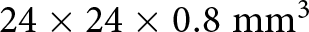
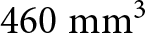
  $24 \times 24 \times 0.8\;{\textrm{m}}{{\textrm{m}}^3}$ ( $460\;{\textrm{m}}{{\textrm{m}}^3}$) while the PIFA antenna presented in paper [Reference Jayasinghe and Uduwawala26] is $30 \times 7 \times 5.8\;{\textrm{m}}{{\textrm{m}}^3}$ ( $1218\;{\textrm{m}}{{\textrm{m}}^3}$) and $37 \times 24 \times 4\;{\textrm{m}}{{\textrm{m}}^3}$ (3 $552\;{\textrm{m}}{{\textrm{m}}^3}$) for the PIFA presented in paper [Reference Wakrim, Ibnyaich and Hassani27]. The methodology presented can then be very effective in terms of size reduction.
Table 6. Performance comparison of this work to PIFA multiband antenna

Conclusion
A GA with multi-objective fitness functions and parallel computing is applied to design three Minkowski Island fractal antennas for the WiFi-5 standard. The optimization process is accelerated by using the CST Application Programming Interface which allows all genetic operators to be performed in MATLAB while the numerical calculations are running the internal CST FDTD-solver using parallel computing and with GPU acceleration. This method allowed us to considerably reduce the convergence time. The whole process was then  $9$ times faster than normal. With single-objective GA-based optimization, a wideband antenna can be designed with high occupancy of the targeted band ( $92\text{%}$ for the first antenna). While the optimization based on the multi-objective fitness function allows the designing of a multiband antenna with narrow bands and with many channels ( $14$ channels for the braided band antenna).
Competing interests
The authors report no conflict of interest.

Bouchra Ezzahry was born in Fnideq, Morocco, in 1991. She received her License degree in 2013. She obtained her master’s degree in Electronics and Telecommunications in 2015 from the Abdelmalek Essaadi University Tetouan, Morocco. She follows her research in the laboratory of information systems and telecommunications. She is currently pursuing her Ph.D. research in the field of optimization of fractal microstrip antennas using the genetic algorithm (GA).

Tajeddin Elhamadi was born in Alhoceima, Morocco, in 1982. He obtained his master’s degree in Electronics and Telecommunications in 2013 from Abdelmalek Essaadi University. In 2017, he obtained his Ph.D. degree in Physics from Abdelmalek Essaadi University, Tetouan, Morocco. Currently, Elhamadi is a researcher at the Faculty of Sciences at Abdelmalek Essaadi University. He directs his research in the information systems and telecommunications laboratory. His research work focuses on the characterization and modeling of microwave devices using neural networks, as well as the design of microwave circuits in GaAs and GaN MMIC technology. His research interests also include the optimization of planar circuits using evolutionary algorithms. In particular, the optimization of planar antennas by the genetic algorithm and the particle swarm optimization algorithm. Recently, he was introduced to the field of artificial intelligence and machine learning and their applications in the field of robotics and self-driving.

Mohammed Lamsalli was born in Kenitra, Morocco, in 1980. He received his bachelor’s degree in 2006 from the Univ. Ibn Tofail (Science FS – Kenitra). In 2010, he took his master’s degree from the University Abdelmalek Essaâdi (Science FS – Tetouan). He completed his Ph.D. in 2019 at Abdelmalek Essaadi University (Faculty of Sciences – Tetouan) in the field of electronics and telecommunications. His research focused on optimizing passive and active structures through the utilization of genetic algorithms. He received DESA in Instrumentation and Electronics and Ph.D. degree in Electronics and Telecommunication from the University of Abdelmalek Essaadi in 2002 and 2009, respectively. He received the AECID scholarship from the Spanish Ministry of Foreign Affairs (2005–2008) and participated in several research projects. He is an associate professor of electronics and telecommunications at the University of Abdelmalek Essaadi and a member of EIRT.

Naima Amar Touhami received DESA in Instrumentation and Electronics and Ph.D. degree in Electronics and Telecommunication from the University of Abdelmalek Essaadi in 2002 and 2009, respectively. She received the AECID scholarship from the Spanish Ministry of Foreign Affairs (2005–2008) and participated in several research projects. She is an associate professor of electronics and telecommunications at the University of Abdelmalek Essaadi and a member of EIRT. She has supervised master’s and bachelor’s degree students. She has more than 40 journal papers and 40 conference papers. She has participated in the organization of some conferences and events for Ph.D. students. Her research interests include synthesis of advanced high-performance active and passive circuits such as antennas, filters, diplexer, amplifier, and mixer.


