


Introduction
A reverberation chamber (RC) is an electrically large room with metallic walls. When the equipment under test (EUT) is transmitting in the RC, statistically uniform field strength distributions can be created through stirring. The uniform field strength distribution is equivalent to an environment of statistically uniform multipath illumination where each point is equally likely to be illuminated from all directions [Reference Hill1, Reference Andrie2]. RCs are extensively used for wireless equipment measurements, e.g., to measure the total radiated power (TRP) from wireless devices [Reference Furht and Ahson3]. RCs are also used as exposure systems for in vivo bioassays due to their ability to generate uniform fields [Reference Andrie2]. Dosimetric whole-body specific absorption rate (WBSAR) measurements with uniform illumination from all directions (multipath) have been performed in RCs at 1, 1.5, and 2 GHz [Reference Wang, Suzuki, Fujiwara and Hariama4]. However, the multipath propagation environment that characterizes the RC might seem, at a first glance, unsuitable to evaluate WBSAR for electromagnetic field (EMF) product compliance of a base station (BS), which is usually evaluated in free space conditions. At frequencies below 6 GHz, Kvarnstrand et al. [Reference Kvarnstrand, Schilliger Kildal, Skårbratt and Schilliger Kildal5] and Gifuni et al. [Reference Gifuni, Adil, Grassini, Buono, Nunziata, Micheli and Migliaccio6] proposed a solution to isolate the contribution to the absorbed power in a phantom caused by direct illumination from a mobile phone from the power absorbed in the phantom due to the multipath illumination in the RC. In paper [Reference Eilers Bischoff7], a similar method was initially developed to assess WBSAR for BSs at millimeter-wave (mmWave) frequencies. In this paper, the method proposed in paper [Reference Eilers Bischoff7] is employed to study the exposure from an mmWave BS. Moreover, an important scenario for mmWave BS, namely beam steering, is considered in this paper. That is, for the first time, the WBSAR is evaluated, both experimentally and numerically, for different beam steering states. A part of this work was presented at the Swedish Microwave Days 2023.
Background
EMF compliance assessments of BS
When placed on the market, BS products must comply with regulatory requirements and applicable limits on human exposure to radio frequency EMFs, such as those specified by the International Commission on Non-Ionizing Radiation Protection (ICNIRP) [8]. In the ICNIRP 2020 guidelines [8], two sets of EMF exposure limits are provided, the so-called basic restrictions and reference levels. The basic restrictions relate to physical quantities in the body, e.g., the specific absorption rate (SAR), which is defined as follows:
 \begin{equation}\begin{array}{*{20}{c}}
{SAR = \frac{{\boldsymbol{d}}}{{{\boldsymbol{dt}}}}\left( {\frac{{{\boldsymbol{dW}}}}{{{\boldsymbol{dm}}}}} \right)\,}
\end{array}\end{equation}
\begin{equation}\begin{array}{*{20}{c}}
{SAR = \frac{{\boldsymbol{d}}}{{{\boldsymbol{dt}}}}\left( {\frac{{{\boldsymbol{dW}}}}{{{\boldsymbol{dm}}}}} \right)\,}
\end{array}\end{equation} where  $t$ [s] is time, $W\,$[J] is the energy absorbed in the tissue, and $m$ [kg] is the mass of tissue [8]. SAR can also be expressed equivalently as follows:
 \begin{equation}\begin{array}{*{20}{c}}
{SAR = \frac{{\boldsymbol{\sigma }}}{{\boldsymbol{\rho }}}{{\left| {\boldsymbol{E}} \right|}^2}}
\end{array}\end{equation}
\begin{equation}\begin{array}{*{20}{c}}
{SAR = \frac{{\boldsymbol{\sigma }}}{{\boldsymbol{\rho }}}{{\left| {\boldsymbol{E}} \right|}^2}}
\end{array}\end{equation} where  $\sigma $ [S/m] is the conductivity of tissue, $\rho $ [kg/m3] is the density of tissue, and $E$ [V/m] is the root-mean-square of the induced electric field (E-field) [8]. For local exposure assessments, $SAR$ is intended to be averaged over a cubical mass of 10 g tissue. For whole-body exposure assessment, SAR can be calculated as the total power absorbed in the body ${P_{abs}}$ [W] averaged over the body mass ${m_{wb}}$ [kg] [8]:
 \begin{equation}\begin{array}{*{20}{c}}
{WBSAR = \frac{{{{\boldsymbol{P}}_{{\boldsymbol{abs}}}}}}{{{{\boldsymbol{m}}_{{\boldsymbol{wb}}}}}}\,.}
\end{array}\end{equation}
\begin{equation}\begin{array}{*{20}{c}}
{WBSAR = \frac{{{{\boldsymbol{P}}_{{\boldsymbol{abs}}}}}}{{{{\boldsymbol{m}}_{{\boldsymbol{wb}}}}}}\,.}
\end{array}\end{equation}WBSAR is intended to be averaged over 30 minutes. The 2020 ICNIRP [8] guidelines extended the applicability of WBSAR up to 300 GHz compared with the previous version of the guidelines [9], while the usage of local SAR is limited to 6 GHz [8]. Reference levels, on the other hand, are defined in terms of external physical quantities, e.g., incident power density [W/m2] [8], and the limits are derived from the basic restrictions to provide a more-practical means of demonstrating compliance [8]. While compliance of mmWave BSs can be assessed by means of the reference levels [Reference Colombi, Xu, Anguiano Sanjurjo, Joshi, Ghasemifard, Di Paola and Törnevik10], the availability of an efficient and accurate WBSAR measurement method is complementary to assess compliance directly with the whole-body basic restrictions introduced by ICNIRP.
Generally, the product compliance evaluation process consists of determining the BS compliance boundaries (exclusion zones) outside of which exposure is below the EMF limits (reference levels or basic restrictions). BSs are subsequently installed to prevent access to the compliance boundary. The EMF product compliance assessment of a BS is done in free space (excluding any possible impact from ambient sources and scatterers that need to be considered in an installation assessment) except for the human phantom when the evaluation is based on basic restrictions [11]. The phantoms’ characteristics as well as the evaluation methods are specified in international standards, such as IEC 62232 [11]. IEC 62232 provides WBSAR measurement methods, which are generally based on scanning of the phantom with an E-field probe, applicable below 6 GHz. The same method is not directly applicable at mmWave frequencies due to the shallow field penetration depth in the phantom (of few millimeters or less) that poses substantial challenges on sensitivity and dimension of the probe. Furthermore, E-field scanning with a sub-wavelength step size requires hundreds of points to be measured, making the measurement times untenable at mmWave frequencies [11].
Measuring the TRP in an RC
To perform a TRP measurement of a EUT, the RC must be well stirred, and the RC should contain a reference antenna with known radiation efficiency and a receiving antenna. The first step is to determine the chamber transfer function  $G$, which is defined as [Reference Furht and Ahson3] follows:
 \begin{equation}\begin{array}{*{20}{c}}
{G = \frac{{{{\boldsymbol{P}}_{{\boldsymbol{Rx}}}}}}{{{{\boldsymbol{P}}_{{\boldsymbol{Tx}}}}}}\,}
\end{array}\end{equation}
\begin{equation}\begin{array}{*{20}{c}}
{G = \frac{{{{\boldsymbol{P}}_{{\boldsymbol{Rx}}}}}}{{{{\boldsymbol{P}}_{{\boldsymbol{Tx}}}}}}\,}
\end{array}\end{equation} where  ${P_{Rx}}$ is the power received by the receiving antenna, ${P_{Tx}}$ is the TRP of a source (the reference antenna or the EUT), and 〈 〉 is the mean value over time. A vector network analyzer (VNA), with Port 1 connected to the reference antenna and Port 2 connected to the receiving antenna, as illustrated in Fig. 1, is used to determine G using the following equation [Reference Furht and Ahson3]:
 \begin{equation}\begin{array}{*{20}{c}}
{G = \frac{{{{\left| {{{\boldsymbol{S}}_{21}}} \right|}^2}}}{{\left( {1 - {{\left| {{{\boldsymbol{S}}_{11}}} \right|}^2}} \right){{\boldsymbol{\eta }}_{{\boldsymbol{ref\,}}}}}}\,}
\end{array}\end{equation}
\begin{equation}\begin{array}{*{20}{c}}
{G = \frac{{{{\left| {{{\boldsymbol{S}}_{21}}} \right|}^2}}}{{\left( {1 - {{\left| {{{\boldsymbol{S}}_{11}}} \right|}^2}} \right){{\boldsymbol{\eta }}_{{\boldsymbol{ref\,}}}}}}\,}
\end{array}\end{equation}
Figure 1. Illustration of the chamber transfer function measurements and the S parameters.
where  ${S_{21}}$ is the transmission coefficient between the reference and receiving antennas, ${S_{11}}$ is the reflection coefficient of the reference antenna, and ${\eta _{ref}}$ is the known radiation efficiency of the reference antenna. Thus, ${\left| {{S_{21}}} \right|^2}$ is the average net power transmission from the receiving antenna to the reference antenna, and $\left( {1 - {{\left| {{S_{11}}} \right|}^2}} \right)\,$accounts for the power loss due to reflections in the reference antenna. In a well-stirred chamber, G is independent off the source and antenna position (as long as the separation distance from the antenna to the chamber walls is larger than the reactive near-field distance [Reference Hill1]). As such, $G$ is the normalized average net power transmission from any EUT to the receiving antenna [Reference Furht and Ahson3]. Using $G$ the TRP of a EUT is then calculated as follows [Reference Furht and Ahson3]:
 \begin{equation}\begin{array}{*{20}{c}}
{{{\boldsymbol{P}}_{{\boldsymbol{Tx}}}} = \frac{{{{\boldsymbol{P}}_{\boldsymbol{r}}}}}{{{\boldsymbol{GL}}}}}
\end{array}\end{equation}
\begin{equation}\begin{array}{*{20}{c}}
{{{\boldsymbol{P}}_{{\boldsymbol{Tx}}}} = \frac{{{{\boldsymbol{P}}_{\boldsymbol{r}}}}}{{{\boldsymbol{GL}}}}}
\end{array}\end{equation} where  ${P_r} = L \cdot {P_{Rx}}\,$is the received power measured by a spectrum analyzer and $L$ is the losses in the cable from the receiving antenna to signal analyzer not accounted for in $G$ in accordance with the S parameters definition in Fig. 1.
Method
Measuring WBSAR using TRP measurements
The method of measuring the TRP was extended to measure WBSAR. The chamber transfer function  ${G_u}$ without the phantom, i.e., the unloaded RC, was measured with a VNA and applying Equation (5), as can be seen in Fig. 2a. The received power for the EUT transmitting in the unloaded RC ${P_{r{\text{|u}}}}$ was measured with a signal analyzer (Fig. 2b), and the TRP of the EUT ${P_{Tx{\text{|u}}}}$ was calculated using Equation (6) and ${G_u}$. The phantom was then placed in the RC directly in front of the EUT and the chamber transfer function for the loaded RC, ${G_l}$, was measured with a VNA using the reference antenna and Equation (5) (Fig. 2c). The reference antenna was positioned to avoid direct illumination on the phantom, so ${G_l}$ only accounted for the multipath losses including power absorbed in the phantom due to multipath illumination. Then, the received power for the EUT transmitting in the loaded RC ${P_{r|{\text{l}}}}$ was measured as described in Fig. 2d. Applying Equation (6) with ${G_l}$ and ${P_{r{\text{|l}}}}$ gives ${P_{Tx|{\text{l}}}}$. As such, ${P_{Tx{\text{|l}}}}$ provided the net EUT TRP including absorption due to direct illumination on the phantom. The absorbed power ${P_{Abs|Dir}}$ excluding the effect of the chamber multipath reflections is therefore calculated as follows:
 \begin{equation}\begin{array}{*{20}{c}}
{{{\boldsymbol{P}}_{{\boldsymbol{Abs}}|{\boldsymbol{Dir}}}} = {{\boldsymbol{P}}_{{\boldsymbol{Tx}}{\text{|u}}}} - {{\boldsymbol{P}}_{{\boldsymbol{Tx}}{\text{|l}}}}.}
\end{array}\end{equation}
\begin{equation}\begin{array}{*{20}{c}}
{{{\boldsymbol{P}}_{{\boldsymbol{Abs}}|{\boldsymbol{Dir}}}} = {{\boldsymbol{P}}_{{\boldsymbol{Tx}}{\text{|u}}}} - {{\boldsymbol{P}}_{{\boldsymbol{Tx}}{\text{|l}}}}.}
\end{array}\end{equation}
Figure 2. Diagrams of the four steps to measure WBSAR in an RC. (a) Measurement of the unloaded chamber transfer function. (b) Measurement of the EUT TRP. (c) Measurement of the loaded chamber transfer function, with the reference antenna facing away from the phantom. (d) Measurement of the net EUT TRP when the EUT is directly illuminating the phantom.
WBSAR was then obtained by using Equation (3). The body mass  ${m_{WB}}$ was conservatively chosen as the whole-body child mass of 12.5 kg specified in IEC 62232 [11]. The steps in Fig. 2(a) and (c) to characterize the chamber transfer functions ${G_u}$ and ${G_l}$ were conducted once for a specific EUT. The measurements of ${P_{Tx{\text{|u}}}}\,$(Fig. 2(b)) depend on the EUT configurations (in terms of the selected frequency band, channel, or operating beam) and were repeated for each EUT configuration. ${P_{Abs|Dir}}$ is additionally dependent on the distance and orientation of the EUT with respect to the phantom. Hence, for each EUT-phantom distance, the step described in Fig. 2(d) was repeated.
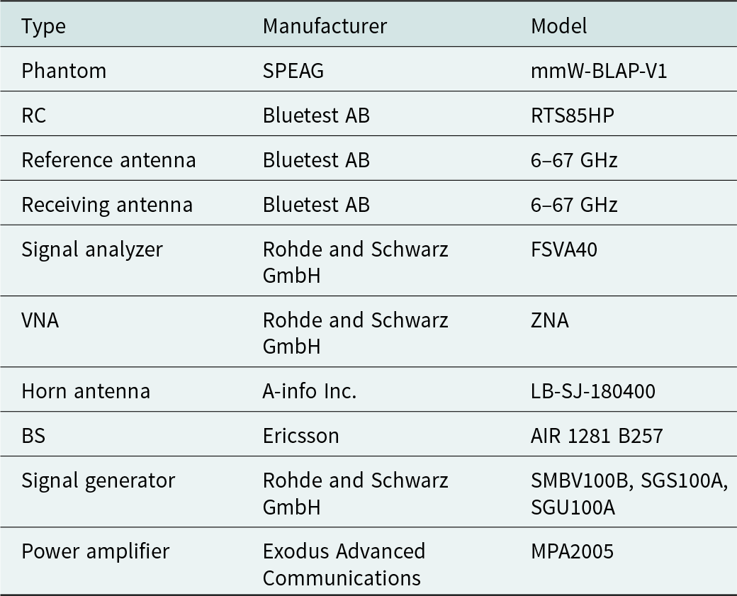
Equipment
The measurement setup inside the Bluetest RTS85HP RC is shown in Fig. 3. The dimension of Bluetest RTS85HP is 2260 mm × 2360 mm × 2480 mm. The RC can operate from 450 MHz to 67 GHz. A list of equipment is presented in Table A1. Mechanical stirring, source moving stirring, and frequency stirring were used for the chamber transfer function measurements; mechanical stirring together with source moving stirring were used for the TRP measurement. Two EUTs including an A-INFO horn antenna and an Ericsson AIR 1281 B257 mmWave BS were measured in the RC. The maximum gain, measured TRP, and half power beam width (HPBW) of the EUTs are presented in Table 1. A signal generator and a power amplifier were used to feed the horn antenna. The AIR 1281 has beam steering and was set to operate constantly at the maximum rated TRP with a fixed beam for each measurement. Two beams were selected for the measurements, the boresight beam and a steered beam. The steered beam was steered  $ - {60^ \circ }\,\,$vertically and $ - {15^ \circ }\,\,$horizontally from boresight. Both EUTs were set up to transmit a 5G test signal (3GPP conformance test model TM 3.1 [12]) at a center frequency of 28 GHz with a bandwidth of 100 MHz.
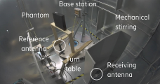
Figure 3. Measurement setup inside of the RC.
Table 1. Horn antenna and AIR 1281 max gain, TRP, horizontal and vertical HPBW

Currently, no phantom for evaluating WBSAR above 6 GHz has been standardized. The SPEAG mmW-BLAP-V1 rectangular-shaped phantom (375 mm × 325 mm × 75 mm) was used in this study. The phantoms bulk material has relative permittivity of  $18.6$ and conductivity of $6.24$ S/m at 28 GHz [13]. The phantom also has a coating with a maximum thickness of 0.2 mm, permittivity of 3.5, and conductivity of 1 S/m. This cuboid-shaped phantom was not explicitly designed for the purpose of characterizing WBSAR at mmWave frequencies, but its dielectric parameters are of relevance for the investigated band. A wooden cart was used to position the phantom in front of the transmitting antenna as can be seen in Fig. 3. ${G_l}$ and ${G_u}$ consider the losses in the wooden cart. In this study, the separation distance from the EUT to the phantom was varied from 1 to 70 cm.
Simulation
The WBSAR simulations with the phantom and EUTs were performed in CST Studio Suite 2022, using the integral solver based on the multilevel fast multipole method. Simplified models of the horn and the AIR 1281 were used. The horn antenna was made from perfect electric conductor (PEC) and a waveguide port. The AIR 1281 antenna array was simulated using the time-domain solver, a maximum cell size of 15 cells per wavelength, to produce an equivalent field source, which was imported into the integral solver, as can be seen in Fig. 4. The main body of the AIR 1281 was approximated by a PEC backplate placed on the back of the field source, which was used to model the reflections between the BS and the phantom.

Figure 4. Illustration of the simulation of AIR 1281 and phantom.
The difference of the maximum gain and HPBW of the simplified antenna models were within 2% of the values in Table 1. The phantom was modeled as a PEC with coating that has the same surface properties as the mmW-BLAP-V1 phantom. The thickness of the coating was five times that of the skin depth to ensure all transmission into the phantom is absorbed, and the integral solver computes the total absorbed power inside the phantom by summing up the surface impedance loss while not computing the field inside the phantom to greatly reduce computational resource demands. The maximum cell size in the integral solver was 7 cells per wavelength for the horn and 10 cells per wavelength for the AIR 1281. In order to compare numerical and experimental data, the transmitted power in the simulation was set equal to the antenna TRP as measured in the chamber.
Results
The WBSAR simulations and measurement results for the AIR 1281 and horn antenna are presented in Fig. 5. The WBSAR measurements were performed at nine separation distances between the EUT and phantom from 1 to 70 cm. Simulations and measurements are in very good agreement with an average difference in WBSAR of 2% for the AIR 1281 boresight beam and 11% for the horn antenna. The corresponding maximum difference is 4% and 13% for the AIR 1281 and the horn antenna, respectively. The average and maximum difference for the steered beam of the AIR 1281, for separation distances from 1 to 10 cm is 18% and 34%, respectively. The difference between measurements and simulations is due to the measurement uncertainty as well as to the approximation in the numerical models. WBSAR decreases with the increasing EUT-phantom separation distance, since the phantom becomes smaller compared to the beam size at increasing separation distances. For distances larger than 10 cm, almost no energy from the steered beam of AIR 1281 intercepts the phantom, and WBSAR for this configuration is almost zero (due to the uncertainty, when  ${P_{Tx{\text{|l}}}}$ approaches ${P_{Tx{\text{|u}}}}\,$, the calculated ${P_{Abs|Dir}}$ can be negative; in this case, the measured WBSAR was set to zero).

Figure 5. WBSAR measurement and simulation results for the AIR 1281 mmWave massive MIMO BS and the horn antenna.
The smallest EUT-phantom separation distance of 1 cm gave the largest WBSAR at 0.035 W/kg for AIR 1281 boresight beam (with TRP of 440 mW), 0.025 W/kg for AIR 1281 steered beam (with TRP of 330 mW) and 0.009 W/kg for the horn antenna (with TRP of 160 mW). All the measurements are well below the 0.08 W/kg WBSAR limit specified in ICNIRP 2020 and applicable for the general public.
Discussion
The results show good agreement between measurements and simulations. The method provides an innovative and efficient way to measure WBSAR at mmWave frequencies, in accordance with the ICNIRP 2020 guidelines. When  ${G_{u\,}}{\text{and }}{G_l}$ are established, a WBSAR measurement can be done in 3 minutes (with the measurements of ${P_{Tx|u}}\,{\text{and }}{P_{Tx|l}}$ taking 1.5 minutes each). The measurements of the chamber transfer functions are performed only once with ${G_{u\,}}{\text{and }}{G_l}$ taking 15 minutes each.
Future studies will be needed to characterize the uncertainty of the measurement method. For instance, a limitation with the proposed methodology is that the phantom, when in proximity of the EUT, could induce an antenna mismatch which cannot be experimentally evaluated if the antenna ports are not accessible. With the given methodology, the power which is reflected at the antenna port is assumed absorbed by the phantom, possibly leading to an overestimate of WBSAR, when measured at small EUT-phantom separation distances. The frequency range of the method should also be investigated since RCs can operate at frequencies lower and higher than 28 GHz; the method could potentially help with reducing the measurement time at the lower frequencies compared with conventional methods applicable below 6 GHz.
For transmitters operating below 1 W (or more, if the BS is installed at a minimum height of 2.2 m) compliance with the whole-body exposure limits can generally be shown by means of exclusion criteria [11] without requiring any further assessment. For higher power levels, WBSAR measurements in RC provides a solution for assessing product compliance of BSs directly with the ICNIRP basic restrictions and for separation distances of 1–2 m depending on the size of the RC.
Conclusions
An efficient method to measure WBSAR from mmWave BSs has been presented in this paper. The method is based on measuring the TRP of the EUT and the TRP from the EUT and phantom combined, whose difference results in the phantom total absorbed power. The contribution from absorption due to the EUT direct illumination of the phantom is distinguished from that caused by the multipath reflections in the RC, making this technique suitable for EMF product compliance assessment with ICNIRP 2020 whole-body basic restrictions of BSs for short separation distances (as limited by the dimension of the RC). Comparing simulations to measurements demonstrates good agreement at 28 GHz. For the beam configuration leading to maximum exposure, the difference between simulations and measurements for the Ericsson AIR 1281 massive multi-input–multi-output BS was on average 2% and at maximum 4%. For the horn antenna the average difference was below 13%. Furthermore, the measurements are fast, with each measurement taking 3 minutes once the chamber transfer functions have been established.
Competing interests
The author(s) declare none.
Appendix
Table A1. List of equipment

Jens Eilers Bischoff received the B.S. and M.S. degrees in electrical engineering from KTH Royal Institute of Technology in 2022. He is currently working with Ericsson Research, Stockholm, Sweden, with research related to radio frequency exposure from wireless communication equipment, specifically 5G.

Paramananda Joshi received the B.E. degree in electronics and communication from Tribhuvan University, Kathmandu, Nepal, in 2008, and the M.Sc. degree in wireless communication from Lund University, Lund, Sweden, in 2012. Since 2012, he has been with Ericsson Research, Stockholm, Sweden, where he is currently working as a Senior Researcher and also involved in research activities related to realistic radio frequency (RF) electromagnetic fields (EMF) exposure from radio base stations and user devices. Since 2016, he has been working as the Technical Manager of the Ericsson EMF Research Laboratory, Stockholm.

Davide Colombi received the M.Sc. degree (summa cum laude) in telecommunication engineering from the Politecnico di Milano, Milan, Italy, in 2009. Since 2009, he has been with Ericsson Research, Stockholm, Sweden, where he is currently working with research related to radio frequency exposure from wireless communication equipment, particularly for 5G. Mr. Colombi was a recipient of the 2018 IEC 1906 Award. He has contributed to the development of IEC, ITU, and the IEEE standards on the assessment of radio frequency exposure from wireless equipment as an Expert, an Editor, and a Convener.

Bo Xu received the B.E. degree in information engineering from Zhejiang University, Hangzhou, China, in 2010, and the Ph.D. degrees (joint doctoral program) in optical engineering and electrical engineering from Zhejiang University, Hangzhou, China, and from the KTH Royal Institute of Technology, Stockholm, Sweden, in 2017 and 2021, respectively. He has been with Ericsson Research, Ericsson AB, Stockholm, Sweden, since 2018, and currently is a Senior Specialist in EMF Compliance Solutions. His research interests include electromagnetic field health and safety, mobile communication technologies, and antenna measurements. Dr. Xu has been an expert in the IEC Technical Committee 106 Joint Maintenance Team 62209-3 since May 2021.

Christer Törnevik (Member, IEEE) received the M.Sc. degree in applied physics from the Linköping University, Linköping, Sweden, in 1986, and the Licentiate degree in materials science from the Royal Institute of Technology, Stockholm, Sweden, in 1991. He joined Ericsson in 1991. Since 1993, he has been involved in research activities related to radio frequency exposure from wireless communication equipment. He is currently a Senior Expert with responsibility for electromagnetic fields and health within the Ericsson Group. From 2003 to 2005, he was the Chairman of the Mobile and Wireless Forum, where he is currently the Secretary of the Board. Since 2006, he has been leading the Technical Committee on electromagnetic fields of the Swedish Electrotechnical Standardization Organization, SEK, and he has as an expert contributed to the development of several CENELEC, IEC, ITU, and IEEE standards on the assessment of RF exposure from wireless equipment.


