


1. Introduction
Most of the arm-type industrial robots currently operating in factories are based on the basic principle of “teaching and playback,” which is originated from George Devol’s patent “Programmed Article Transfer” [Reference Devol1] applied for in 1954 and granted in 1961. Industrial robots based on this traditional “teaching and playback” method have been improved in their performance such as speed and repeatability by improving sensor resolution and rigidity.
However, in order to derive such performances from those robots, peripheral devices such as jigsFootnote 1 are required, which push up the total cost needed for deploying robots to the manufacturing fields. This is the reason why the industrial robots are said to be “partially completed products” [2], resulting in that the industrial robot, which was originally supposed to function as a “programmable general-purpose machine,” had, in most cases, become an “inflexible special-purpose machine,” which is continuously used once integrated as a system. This is the main reason why robots have not spread in small- and medium-sized enterprises (SMEs) where the introduction cost was not worth the small production scale [Reference Perzylo, Rickert, Kahl, Somani, Lehmann, Kuss, Profanter, Beck, Haage, Hansen, Roa, Sornmo, Robertz, Thomas, Veiga, Topp, Kessler and Danzer3].
Nowadays, it is desired not only by SMEs but also by large enterprises that the robot system can be introduced at low cost and be easily reconfigured to a system that manufactures another product, to meet the demands for the variable-mix variable-volume production, due to the diversification of consumer needs and the shortening of product life cycles. In other words, the industrial robot should be reused as a truly “programmable general-purpose machine” [Reference Arai, Aiyama, Maeda, Sugi and Ota4–Reference Bi, Lang, Verner and Orban7].
For this reason, many attempts in hardware and software aimed at agile and lean robot systems have been conducted, especially for the product assembly phase [Reference Perzylo, Rickert, Kahl, Somani, Lehmann, Kuss, Profanter, Beck, Haage, Hansen, Roa, Sornmo, Robertz, Thomas, Veiga, Topp, Kessler and Danzer3, Reference Perzylo, Somani, Profanter, Kessler, Rickert and Knoll8–Reference Duan, Tan, Tong, Kato and Arai11] because it usually takes time and cost to prepare peripheral devices such as special-purpose grippers, jigs, parts feeders, etc. and careful teaching is required for precise parts fitting. Recently, the Assembly Challenge, a robotic competition of the World Robot Summit (WRS) sponsored by the Ministry of Economy, Trade and Industry (METI) and the New Energy and Industrial Technology Development Organization (NEDO), was held under the slogan, “Toward agile one-off manufacturing” [Reference Yokokohji, Kawai, Shibata, Aiyama, Kotosaka, Uemura, Noda, Dobashi, Sakaguchi and Yokoi12–Reference von Drigalski, Nakashima, Shibata, Konishi, Triyonoputro, Nie, Petit, Ueshiba, Takase, Domae, Yoshioka, Ijiri, Ramirez-Alpizar, Wan and Harada16].
There are several approaches for performing assembly work with precise fitting without jigs, such as the force-sensing-based approach and the position-control-based approach. A typical example of the force-sensing-based approach is searching and insertion with compliance control [Reference Wyk, Culleton, Falco and Kelly17]. However, such a force-based approach tends to need a certain time. A self-alignment method, which absorbs the initial position error in the process of grasping the target part, is a typical example of the position-control-based approach. Once the position uncertainty of the part is resolved in the grasping process before conducting the assembly work, it might be possible to be assembled with a conventional industrial robot with high repeatability. If so, it would be beneficial in speed and easiness of implementation compared to the force-based approach.
Needless to say, self-alignment methods have been already used at the production site as a low-cost and reliable alignment method. However, the shape of the target part is limited or hands with customized fingertips are required. In the research field, alignment methods can be traced back to the push operations [Reference Pingle, Paul and Bolles18–Reference Akella and Mason20] and “squeeze grasp” [Reference Brost21, Reference Goldberg22]. Since then, many works have been conducted [Reference Zhang and Goldberg23–Reference Nie, Wan and Harada28], but the shape of the target object is limited in most cases. Bruyninckx et al. [Reference Bruyninckx, Dutre and De Schutter29] and Takahashi et al. [Reference Takahashi, Fukukawa and Fukuda30] focused on the alignment process during the assembly phase, but they dealt with only specific insertion cases.
This paper also focuses on the method of assembling industrial products involving precise fitting without jigs and the development of a robot system that can actually perform jigless assembly, emphasizing the installation cost reduction and the reusability of the robot system rather than the cycle time. Figure 1 shows one scenario for assembling an industrial product without jigs. When performing jigless assembly, it is first necessary to pick up a part from the parts bin with a robotic hand as shown in Fig. 1(a). In Fig. 1(b), the position of the part that was temporarily placed on a work table is roughly recognized by a vision sensor, and the remaining sensing error is automatically corrected in the process of grasping the part (self-alignment) so that the part location with respect to the hand is accurate enough for subsequent assembly operations. Also, note that the counterparts (the shaft, the small gear, and the base plate in the case of Fig. 1(b)) should have also been precisely aligned.
Figure 1. Assumed sequence of jigless assembly.
In this paper, we use a gear unit as an example of industrial products and propose some alignment strategies each of which absorbs the initial position error of each part of the gear unit with a universal hand, which has four parallel stick fingers, mounted on a conventional industrial robot. We also propose some subsequent assembly strategies for shafts and gears, taking advantage of functional flexibility of the four parallel stick fingers and high repeatability of the industrial robot. Using those grasping and assembly strategies, it is shown that jigless assembly of the gear unit was successfully completed in the experiment. In literature [Reference Dobashi, Hiraoka, Fukao, Yokokohji, Noda, Nagano, Nagatani, Okuda and Tanaka31], we have already succeeded in assembling the puzzle called “Soma Cube” [32] by using appropriate alignment strategies. However, the accuracy required for assembling the wooden puzzle was at most $0.5\ \textrm{mm}$
, which is far beyond the accuracy required for assembling industrial products. In addition, since no vision sensor was introduced in ref. [Reference Dobashi, Hiraoka, Fukao, Yokokohji, Noda, Nagano, Nagatani, Okuda and Tanaka31], the information on the nominal positions of the parts should be given to the robot. Therefore, the developed robot system was not completed yet.
$0.5\ \textrm{mm}$
, which is far beyond the accuracy required for assembling industrial products. In addition, since no vision sensor was introduced in ref. [Reference Dobashi, Hiraoka, Fukao, Yokokohji, Noda, Nagano, Nagatani, Okuda and Tanaka31], the information on the nominal positions of the parts should be given to the robot. Therefore, the developed robot system was not completed yet.
The main contributions of this paper can be summarized as follows:
We have demonstrated that “completely-jigless” assembly of a model product that requires fitting accuracy at the level of industrial products is possible by using a universal hand with four parallel stick fingers mounted on a conventional position-control-based industrial robot.
The parts that make up the model product are classified into several groups from the viewpoint of symmetry and graspability of the parts, and the self-alignment strategy for each group is presented.
Then, subsequent position-controlled assembly strategies have been presented for each aligned part.
Although the target product is specific, the assembly elements in this product, such as shaft screwing, bearing insertion, and gear meshing, are also included in many other products. Therefore, the methods shown in this paper can be applied to other products.
The remainder of the paper is organized as follows. Section 2 shows the target product and the system components including the hand used in this paper. Section 3 proposes the alignment strategies and show their robustness, focusing on the parts that are difficult to align by a simple grasping method and the part that cannot be grasped by the hand. Section 4 describes some methods after alignment, such as regrasping the shaft for the subsequent assembly and how to fit the gears onto the shaft. Section 5 shows the experimental result of jigless assembly of the gear unit using an actual industrial robot and discusses the result. Finally, Section 6 summarizes this paper.
2. Target product and system components
2.1. Target product
In this paper, we will focus on the gear unit shown in Fig. 2 as the target product for assembly. This gear unit was the target product for Task 2 of the Manufacturing Track of IROS 2017 Robotic Grasping and Manipulation Competition [33]. The task was also treated as the trial competition of the Assembly Challenge of the WRS. As shown in Fig. 2(a), the gear unit consists of a base plate, shafts, spacers, large and small gears, washers, and nuts. There is no flexible part. The details of the specifications of this gear unit are shown in Appendix A.

Figure 2. Gear unit.
As shown in Appendix A, assembling this gear unit requires not only screw tightening but also precise fitting of the shaft and the bearing inside the gear, and the clearance is in the range of 3–16 µm.
When these parts are placed on the work table, they can be roughly divided into four groups as shown below. Note that even the same parts could be classified into different categories depending on how they are placed. In this paper, a part whose cross-sectional shape horizontal to the work table surface is not constant, i.e. the silhouette is not identical to all of the cross-sectional shapes, is defined as a three-dimensional (3D) shape part.
-
1. Parts in axisymmetric and graspable states
This group includes parts that are symmetrical with respect to the central axis, such as cylindrical parts, and their cross sections are small enough to be grasped by the hand. To be in this group, these parts must be in a state where the central axis is vertical so that its silhouette onto the work table is also axisymmetric. Among the parts of the target product, spacers, washers, nuts, and shafts in an upright position are in this group (Fig. 3(a)). The parts in this group can be grasped by a conventional chucking method.
-
2. Gears
Gears may be included in the previous group if for simply grasping them. However, precise alignment is difficult with the conventional chucking method because it is necessary to determine the position of the teeth when assembling. Therefore, gears are categorized into a different group (Fig. 3(b)).
-
3. Parts in axis asymmetrical and graspable states
This group includes parts that are axis asymmetrical but are small enough to be grasped from those states. Among the parts of the target product, the shafts laid on a work table are in this group (Fig. 3(c)). Parts in this group are difficult to be aligned and grasped stably by the conventional chucking method.
-
4. Parts in ungraspable states
This group includes parts that are larger than the size of the hand and cannot be grasped. Among the parts of the target product, the base plate is included in this group (Fig. 3(d)). Its cross-section is larger than the maximum opening width of the hand, and alignment is not possible with the conventional method. Note that graspable/ungraspable property is not associated with a part but its state. For example, even the base plate can be graspable if it is vertically standing with a supporting jig.
Figure 3. Grouping of the parts of the gear unit.
In Section 3, we propose new grasping strategies for Groups 2, 3, and 4, which are difficult to be aligned or grasped with the conventional method. Although this paper targets only a specific product (gear unit), the grouping strategy shown in this section can be applied to other products and it is expected that the basic concept of the proposed assembly strategies could also be applied to other products as well.
2.2. System components
2.2.1. Universal hand with parallel stick fingers
The universal hand used in this paper is a hand with four parallel stick fingers as shown in Figs. 4(a) and (b) [Reference Dobashi, Hiraoka, Fukao, Yokokohji, Noda, Nagano, Nagatani, Okuda and Tanaka31]. All fingers can move independently, and the total degree of freedom of the hand is four. As shown in Fig. 4(c), each stick finger is equipped with a passively rotating outer tube so that it equivalently makes friction-less contact with the target part in a plane perpendicular to the stick finger, enabling alignment operations with slippage between the finger and the target part. Since the outer tube does not move in the longitudinal direction, the target part can be lifted by applying an appropriate grasping force.
Figure 4. Universal hand with four parallel stick fingers (four fingers independently move linearly and each fingertip can be rotated passively).
The radius of the finger is $5.0\ \textrm{mm}$
, the maximum opening width of the finger is
$5.0\ \textrm{mm}$
, the maximum opening width of the finger is $129\ \textrm{mm}$
, and the minimum width is
$129\ \textrm{mm}$
, and the minimum width is $7\ \textrm{mm}$
.
$7\ \textrm{mm}$
.
As will be shown in Section 5.1, this hand is mounted on the end point of a conventional industrial robot.
2.2.2. Vision sensor
The vision sensor used in this paper is a 2-megapixel monochrome camera (Mitsubishi Electric, VS80M-202-E) shown later in Fig. 20, and the bundled software, “In-Sight Explorer for MELSENSOR Vision” is used to recognize parts. The vision sensor is installed $1100\ \textrm{mm}$
above the work table so that it can view the entire
$1100\ \textrm{mm}$
above the work table so that it can view the entire $640\times 480\ \textrm{mm}$
work table as shown later in Fig. 20. A ring light (Neewer, Model No. 10092440) is installed above for lighting. The ring light has an outer diameter of
$640\times 480\ \textrm{mm}$
work table as shown later in Fig. 20. A ring light (Neewer, Model No. 10092440) is installed above for lighting. The ring light has an outer diameter of $480\ \textrm{mm}$
and an inner diameter of
$480\ \textrm{mm}$
and an inner diameter of $360\ \textrm{mm}$
.
$360\ \textrm{mm}$
.
With this setting, the resolution of the vision sensor is $0.4\ \textrm{mm/px}$
. When parts were recognized at various locations on the work table under the above conditions, the minimum error was
$0.4\ \textrm{mm/px}$
. When parts were recognized at various locations on the work table under the above conditions, the minimum error was $0.7\ \textrm{mm}$
and the maximum error was
$0.7\ \textrm{mm}$
and the maximum error was $4.4\ \textrm{mm}$
. These errors were evaluated as the total errors including the errors of intrinsic and extrinsic camera parameters. Such errors are sufficiently small for the robotic hand to approach a part whose initial position is unknown in advance, but too large for precision parts fitting. Details for this error estimation are shown in Appendix B.
$4.4\ \textrm{mm}$
. These errors were evaluated as the total errors including the errors of intrinsic and extrinsic camera parameters. Such errors are sufficiently small for the robotic hand to approach a part whose initial position is unknown in advance, but too large for precision parts fitting. Details for this error estimation are shown in Appendix B.
3. Grasping strategies for jigless assembly
This section describes grasping strategies involving self-alignment of the target parts and subsequent assembly methods in order to realize jigless assembly of a gear unit by the universal hand with four parallel stick fingers hand mounted on a 6-DOF industrial robot.
3.1. Grasping strategy for shaft
In this subsection, we first propose a grasping strategy for the shaft laid on the work table. When the shaft is laid down on a horizontal plane (the work table), its axis is not parallel but slightly slanted with respect to the horizontal plane as shown in Fig. 5(a). Since the shaft laid down on the work table is a 3D-shaped part, the grasping strategy is planned using the silhouette projected on the work table surface. However, since this part is axially asymmetric in this state, self-alignment by simple chucking is not possible.

Figure 5. Shaft on a horizontal plane.
In the method proposed by Dobashi et al. [Reference Dobashi, Hiraoka, Fukao, Yokokohji, Noda, Nagano, Nagatani, Okuda and Tanaka31], the finger locations that make a form closure [Reference Reuleaux34] with four parallel stick fingers are obtained from the silhouette shape. Since each finger was moved linearly from its initial position to the final grasping position, the variation of the grasping strategy was limited. As a result, the margin of error that could be absorbed (permissible initial pose error region) was also limited. A two-step grasping [Reference Dobashi, Hiraoka, Fukao, Yokokohji, Noda, Nagano, Nagatani, Okuda and Tanaka31], where the hand regrasps a target part at another grasping point suitable for the subsequent assembly operation after alignment, has also been proposed, but the permissible region of initial pose errors is still limited.
In this paper, we consider expanding the variation of the movement of each finger by actively utilizing the sliding contact between the part and the finger. As mentioned in Section 2.2.1, the outer tube of the stick finger rotates freely with the bearing, so equivalent sliding contact can be easily realized. Therefore, for example, it is possible to achieve complete constraint by pinching the target part with two fingers while another finger pushes the part that is partially constrained by pinching.
A grasping strategy based on this idea is shown in Fig. 6. Here, the direction of the shaft axis when the alignment is completed (the vertical direction of the figure) is the $y$
direction, and the direction perpendicular to the shaft axis (the horizontal direction of the figure) is the
$y$
direction, and the direction perpendicular to the shaft axis (the horizontal direction of the figure) is the $x$
direction. In this proposed grasping strategy, grasping is divided into two steps. In the first step, as shown in Fig. 6(a), the initial orientation error of the shaft and the initial position error in the
$x$
direction. In this proposed grasping strategy, grasping is divided into two steps. In the first step, as shown in Fig. 6(a), the initial orientation error of the shaft and the initial position error in the $x$
direction are absorbed by moving two fingers along the
$x$
direction are absorbed by moving two fingers along the $x$
-axis. In the second step, as shown in Fig. 6(b), the position error in the
$x$
-axis. In the second step, as shown in Fig. 6(b), the position error in the $y$
direction is absorbed by moving the upper finger along the
$y$
direction is absorbed by moving the upper finger along the $y$
-axis. At this step, the shaft can move in the
$y$
-axis. At this step, the shaft can move in the $y$
direction by sliding the part against the fingers used for pinching in Step 1, while maintaining the constraint in the
$y$
direction by sliding the part against the fingers used for pinching in Step 1, while maintaining the constraint in the $x$
direction. When the grasp is completed, the shaft is contacted at one point on the upper part, two points on the side surface of the shaft and two points on the lower surface of the convex part, forming a form closure.
$x$
direction. When the grasp is completed, the shaft is contacted at one point on the upper part, two points on the side surface of the shaft and two points on the lower surface of the convex part, forming a form closure.

Figure 6. Proposed grasping strategy of the shaft.
Next, the robustness of the grasping strategy is analyzed. Here, robustness means the tolerance against uncertainties of the initial pose of the part. The quasi-static simulator developed by Dobashi et al. [Reference Dobashi, Hiraoka, Fukao, Yokokohji, Noda, Nagano, Nagatani, Okuda and Tanaka31] is used for robustness analysis. In this simulator, the permissible initial pose error region of the target part under the assumed grasping strategy can be obtained by performing the grasping simulation with various initial poses of the part by grid sampling in the pose space. Figure 5(b) shows the pressure distribution of the shaft on the work table surface, which is required for the grasping simulation on a horizontal plane, obtained by an FEA tool in a 3D CAD software.
For comparison, Fig. 7 shows an example of the grasping strategy that does not actively utilize slip contact like the ones shown in ref. [Reference Dobashi, Hiraoka, Fukao, Yokokohji, Noda, Nagano, Nagatani, Okuda and Tanaka31]. In this grasping strategy, all fingers move simultaneously and grasp the shaft as shown in Figs. 7(a) and (b).

Figure 7. Naive grasping strategy for comparison.
The obtained permissible initial pose error regions of the shaft under the proposed grasping strategy and the naive grasping strategy for comparison are shown in Figs. 8(a) and (b), respectively. Red points in Fig. 8 mean the initial poses where the grasping is successful. The permissible initial pose error region is a set of such red points, but the sampled points in this simulation are so sparse and difficult to evaluate the range of the region. Therefore, a convex hull of the sampled points that approximates the region is shown to make the range easier to understand. It can be said that the wider the range of the convex hull, the higher the robustness of the assumed grasping strategy. As shown in Fig. 8, the convex hull range for the proposed grasping strategy is wider in all components in $x$
,
$x$
, $y$
(translational errors) and
$y$
(translational errors) and $\theta$
(rotational error) directions than those for the naive strategy, meaning that the proposed grasping strategy is much more robust than the naive method for comparison.
$\theta$
(rotational error) directions than those for the naive strategy, meaning that the proposed grasping strategy is much more robust than the naive method for comparison.

Figure 8. Permissible initial pose error region (sampling intervals are $20\ \textrm{mm}$
,
$20\ \textrm{mm}$
, $5\ \textrm{mm}$
, and
$5\ \textrm{mm}$
, and $5^{\circ}$
in
$5^{\circ}$
in $x$
,
$x$
, $y$
, and
$y$
, and $\theta$
directions, respectively).
$\theta$
directions, respectively).
3.2. Grasping strategy for gears
3.2.1. For gears with even numbers of teeth
This section describes the grasping strategy for gears. In this paper, we will align gears accurately up to the level of gear tooth position. This makes the subsequent assembly easy, as will be described in Section 4.2.
We focused on the gap between the teeth of the gear for accurate alignment. The gear unit used in this paper has two gears (large and small ones), and both of them have even numbers of teeth (40 for the large gear and 30 for the small gear, respectively). So we will first discuss the grasping strategy for gears with even numbers of teeth.
As for the large gear, since the number of teeth is a multiple of 4, all fingers can go into the tooth gap by evenly narrowing the four fingers towards the center of the gear, and the gear pose is uniquely determined as shown in Fig. 9. Note that the initial position of the gear center can be obtained with the vision sensor, and its position accuracy is enough for this alignment operation.

Figure 9. Proposed grasping strategy of the large gear.
When the number of teeth is NOT a multiple of 4, like the small gear, we propose another grasping strategy, which is divided into three steps as shown in Fig. 10. In the first step, caging [Reference Makita and Wan35] is performed so that all fingers evenly come close to the gear so that the position error becomes sufficiently small. In the second step, only two opposing fingers are narrowed towards the center of the gear until they fit into the gap between the teeth. This makes it possible to uniquely determine the position of the teeth. Finally, the grasp is completed by closing the remaining two fingers in the third step until they hit the tooth tips.

Figure 10. Proposed grasping strategy of the small gear.
The robustness of the proposed grasping strategy is analyzed by the quasi-static grasping simulator. When the target part has a lot of uneven contours like a gear, the simulator used in this paper tends to cause the finger to penetrate into the part, and even if the alignment is actually successful in reality, it may be in failure in the simulation. To avoid this, we decided to derive the permissible initial pose error region by approximating the shape of the gear as a simple circle (the tooth tip circle).
The permissible initial pose error regions of the large and small gears can be obtained by assuming a certain initial finger position. Note that if we set the initial finger position wider, we could make the permissible initial pose error regions wider but the grasping process takes longer. Since it is sufficient for the permissible initial pose error region to cover the error of the vision sensor, we determined the initial hand position such that the permissible initial pose error region can be approximated by a rectangular $(x,\ y) = (\!\pm\! 10,\ \pm 10)\,[\textrm{mm}]$
. Figure 11 shows the obtained regions when each finger opened
$(x,\ y) = (\!\pm\! 10,\ \pm 10)\,[\textrm{mm}]$
. Figure 11 shows the obtained regions when each finger opened $58\ \textrm{mm}$
for the large gear and
$58\ \textrm{mm}$
for the large gear and $48\ \textrm{mm}$
for the small gear. The boundary of the region can be determined from several factors. In the case of the large gear, each of the four edges is a locus of the gear center while contacting one of the fingers at the initial finger position. In the case of the small gear, four sharp corners shown in the case of the large gear are rounded because the gear at the corresponding positions slips through between the fingers in the process of closing the fingers.
$48\ \textrm{mm}$
for the small gear. The boundary of the region can be determined from several factors. In the case of the large gear, each of the four edges is a locus of the gear center while contacting one of the fingers at the initial finger position. In the case of the small gear, four sharp corners shown in the case of the large gear are rounded because the gear at the corresponding positions slips through between the fingers in the process of closing the fingers.

Figure 11. Permissible initial pose error regions of the large and small gears.
3.2.2. For gears with odd numbers of teeth
In general, two adjacent gears are selected such that the numbers of teeth are relatively prime. Therefore, we sometimes need to use gears with odd numbers of teeth. For gears with odd numbers of teeth, we cannot close four fingers towards the center of the gear and thus need to prepare a different strategy from that for the gears with even numbers of teeth.
A possible strategy for gears with odd numbers of teeth is shown in Fig. 12.Footnote 2 First, the gear is placed vertically on a flat table, so that it stands stably with two contact points through two teeth at the bottom. Now the orientation of the gear is uniquely determined, and the gear can be grasped from the side with two fingers (not towards the center of the gear but with a certain offset obtained from the gear dimension information), and then from the top with one finger.

Figure 12. Proposed grasping strategy of a gear with an odd number of teeth.
If the vision sensor can recognize the teeth positions precisely enough, the gear need not be placed vertically, and the same grasping strategy shown in Fig. 12 can be applied on the horizontal plane.
3.3. Alignment of the base plate
Parts like the base plate are usually firmly fixed and accurately positioned with a special jig. In this paper, however, this base plate is also aligned by the hand without using a jig.
As described in Section 2.1, the base plate placed flat on the work table is not in the graspable state because the width of the plate is larger than the maximum opening width of the fingers. Since this base plate does not need to be lifted for assembly, we will take a pushing strategy for alignment like Akella and Mason [Reference Akella and Mason20] did. Specifically, the strategy is to open two adjacent stick fingers by an appropriate distance and push the sides of the base plate from four directions as shown in Fig. 13. Defining the long side direction of the base plate after correct alignment as $x$
-axis and the short side direction as
$x$
-axis and the short side direction as $y$
axis, the strategy begins to push the long side from the
$y$
axis, the strategy begins to push the long side from the $-y$
direction followed by pushing the next side in clockwise order.
$-y$
direction followed by pushing the next side in clockwise order.

Figure 13. Base plate alignment procedure (the opening width of the two fingers is $90$
,
$90$
, $30$
,
$30$
, $90$
, and
$90$
, and $70\ \textrm{mm}$
, respectively, from the first to the fourth pushing.
$70\ \textrm{mm}$
, respectively, from the first to the fourth pushing.
For the first and second push operations, the fingers push $10\ \textrm{mm}$
further than the target alignment position to secure a margin for the third and fourth push operations. In addition, although the alignment accuracy is improved when the distance between the two fingers is as large as possible, the finger distance for the second push operation is set a little narrower than that for the fourth push, considering the possibility that the initial error in the
$10\ \textrm{mm}$
further than the target alignment position to secure a margin for the third and fourth push operations. In addition, although the alignment accuracy is improved when the distance between the two fingers is as large as possible, the finger distance for the second push operation is set a little narrower than that for the fourth push, considering the possibility that the initial error in the $y$
direction has not been completely absorbed after the first push.
$y$
direction has not been completely absorbed after the first push.
Figure 14 shows the permissible initial pose error region obtained by the quasi-static simulator. From Fig. 14, one can see that the initial pose error of the base plate can be absorbed by the proposed strategy as long as it is within the range of $(x,\ y,\ \theta ) = (\!\pm\! 20\,[\textrm{mm}],\ \pm 20\,[\textrm{mm}],\ \pm 7.5\,[^{\circ}])$
, where
$(x,\ y,\ \theta ) = (\!\pm\! 20\,[\textrm{mm}],\ \pm 20\,[\textrm{mm}],\ \pm 7.5\,[^{\circ}])$
, where $\theta$
denotes rotation angle of the base plate around the vertical axis. This range can sufficiently cover the error range of pose recognition with a standard camera.
$\theta$
denotes rotation angle of the base plate around the vertical axis. This range can sufficiently cover the error range of pose recognition with a standard camera.

Figure 14. Permissible initial pose error region of the base plate.
3.4. Robustness of aligning cylindrical parts
So far, we have proposed alignment strategies for parts that are asymmetrical and difficult to align or too large and difficult to grasp, among the parts of the gear unit. In this section, we will confirm the permissible initial pose error region for spacers and washers that are graspable and symmetric and can be aligned by a simple chucking strategy, i.e. closing all fingers evenly. Figure 15 shows how the spacer and washer are aligned and grasped.

Figure 15. Grasping strategies for the spacer and washer.
As we did for grasping the large and small gears, we determined the initial hand position such that the permissible initial pose error regions can be approximated by a rectangular $(x,\ y) = (\!\pm\! 10,\ \pm 10)\,[\textrm{mm}]$
, which is wide enough for the pose errors caused by the vision sensor. Figure 16 shows the obtained regions when each finger opened
$(x,\ y) = (\!\pm\! 10,\ \pm 10)\,[\textrm{mm}]$
, which is wide enough for the pose errors caused by the vision sensor. Figure 16 shows the obtained regions when each finger opened $28\ \textrm{mm}$
for the spacer and washer.
$28\ \textrm{mm}$
for the spacer and washer.

Figure 16. Permissible initial pose error regions of the spacer and washer.
Although the nuts are not cylindrical, they were approximated by a circle and the permissible initial pose error region when each finger opened $28\ \textrm{mm}$
was obtained as shown in Fig. 17, due to the same reason for the gears, namely the quasi-static simulator cannot simulate the motion of the nut being pushed by the stick fingers correctly. In the actual experiment, the nuts will be grasped by the following steps, just like the small gear, (i) caging, (ii) pinching by two opposed fingers, (iii) aligning the nut so that it is grasped on the two opposite sides, and (iv) close the remaining two fingers.
$28\ \textrm{mm}$
was obtained as shown in Fig. 17, due to the same reason for the gears, namely the quasi-static simulator cannot simulate the motion of the nut being pushed by the stick fingers correctly. In the actual experiment, the nuts will be grasped by the following steps, just like the small gear, (i) caging, (ii) pinching by two opposed fingers, (iii) aligning the nut so that it is grasped on the two opposite sides, and (iv) close the remaining two fingers.

Figure 17. Permissible initial pose error region of the nut.
4. Regrasping and assembly of parts after alignment
4.1. Regrasping of shafts
If the pose of a grasped part is not suitable for the subsequent assembly even though the initial error has been absorbed by self-alignment, such as a shaft laid down on a work table, it is necessary to regrasp it so that the pose becomes suitable for assembly. In this subsection, we will consider how to regrasp the shaft.
In order to assemble the shaft to the base plate, the shaft must be stood up vertically and grasped from above. However, when the grasping strategy proposed in Section 3.1 is completed, the robot cannot stand up the shaft because one of the fingers is in contact with the end of the shaft which will be in contact with the work table in the standing-up pose as shown in Fig. 6(b). Therefore, it is necessary to regrasp the shaft in order to stand it up vertically.
The proposed regrasping method is shown in Fig. 18. Since the shaft has been precisely aligned already, it is possible to regrasp it accurately at different grasping points as shown in Fig. 18(a). When the regrasping is completed, the shaft can be stood up by tilting the hand $90+\alpha$
[°] as shown in Fig. 18(b), where
$90+\alpha$
[°] as shown in Fig. 18(b), where $\alpha$
denotes the slanted angle of the shaft when laid down on a table (Fig. 5(a)), and it can be assembled into the screw hole by regrasping the shaft again from above as shown in Fig. 18(c). In this method, as shown in Fig. 18, the shaft is aligned perpendicular to the work table in Step 2, and the axis of the shaft is aligned to the hand center by chucking in Step 3.
$\alpha$
denotes the slanted angle of the shaft when laid down on a table (Fig. 5(a)), and it can be assembled into the screw hole by regrasping the shaft again from above as shown in Fig. 18(c). In this method, as shown in Fig. 18, the shaft is aligned perpendicular to the work table in Step 2, and the axis of the shaft is aligned to the hand center by chucking in Step 3.

Figure 18. Regrasping method for standing up the shaft.
Note that when the universal hand described in Section 2.2.1 is used and tilted $90+\alpha \,[^{\circ}]$
in Step 2, the motor part that is radially extending from the top plate of the hand (Fig. 4(a)) will interfere with the table. Therefore, this regrasping operation must be performed at the edge of the table as shown in Fig. 18.
$90+\alpha \,[^{\circ}]$
in Step 2, the motor part that is radially extending from the top plate of the hand (Fig. 4(a)) will interfere with the table. Therefore, this regrasping operation must be performed at the edge of the table as shown in Fig. 18.
4.2. Assembly of the gears
In this subsection, we describe in detail how to assemble the gear to the shaft, which is already screwed on the base plate. As will be shown later in Section 5.2 in detail, the small gear is fitted to the first shaft first and then the large gear is fitted to the second shaft while making mesh to the small gear.
As shown in Section 2.1 and Appendix A, the inner diameter of the ball bearing embedded in the gear and the outer diameter of the shaft are $15\ \textrm{mm}$
. Considering the nominal tolerance of the diameters of the gear and shaft, the maximum fitting gap is 17 µm (clearance fit) and the minimum is −2 µm (interference fit). We purchased several parts and measured the actual distribution of diameters of the gear and shaft with a micrometer. As a result, it turned out that the minimum gap was 3 µm and the maximum was 16 µm and all of them are clearance fits.
$15\ \textrm{mm}$
. Considering the nominal tolerance of the diameters of the gear and shaft, the maximum fitting gap is 17 µm (clearance fit) and the minimum is −2 µm (interference fit). We purchased several parts and measured the actual distribution of diameters of the gear and shaft with a micrometer. As a result, it turned out that the minimum gap was 3 µm and the maximum was 16 µm and all of them are clearance fits.
Regarding the first gear (small gear), the hand can pick it up as it is after the alignment has been completed and fit it into the shaft directly. When a human fits this gear into the shaft, searching and compliant motions are inevitable, requiring a certain amount of time. If the initial pose error is sufficiently absorbed in the grasping process as with the proposed method, the subsequent insertion work can be performed quite easily and faster than humans by simply lowering the gear straight down from a point above the target position by an industrial robot. This assembly strategy is much faster than compliance control and unique to industrial robots that are capable of highly accurate position control.
Regarding the second gear (large gear), it is difficult to engage the teeth and fit the shaft simultaneously even if the gear has been aligned by the proposed method. Therefore, we will take the strategy of giving priority to the gear meshing. Since the small gear is inserted with an exact pose, the position of the teeth is known, and it is possible to perform meshing with the large gear, whose position of teeth is also known by a simple position control, because gears have a certain amount of backlash. In our case, the large gear was moved down until the gear meshing becomes approximately 5 mm wide. When the hand released the large gear after meshing, the large gear settles down to a state shown in Fig. 19(a).

Figure 19. Proposed assembly strategy of the large gear.
Next, as shown in Fig. 19(b), one can spread the four fingers evenly and move them vertically downward to push down and fit the large gear. Since the end points of each finger of the hand are all in the same horizontal plane, the large gear is horizontally aligned while maintaining the engagement with the small gear during the pushing process, and as a result, it is smoothly fitted into the shaft. The reason why we chose the large gear as the second gear is that we can push the gear stably by opening the fingers widely in this strategy.
Even at the manufacturing site, a searching operation is often performed to engage the gears, requiring a certain amount of time. With the proposed method, however, the gears are accurately aligned including the position of the teeth, and such a searching operation is not necessary. Furthermore, by pushing the gear vertically while accurately aligning it horizontally, precise fitting can be achieved without using compliance control, as with the case of the small gear. It has been confirmed that this method was possible for all combinations of the purchased bearings and shafts, where the clearance range spans 3–16 µm.
The gear assembly strategy proposed in this section,Footnote 3 which is confirmed to be possible to make fitting with a gap ranging from 3 to 16 µm, can be used for any industrial robots with high-precision position control capability as long as the pose of the grasped part is known with a certain accuracy. Although the alignment operation is required in advance, this fitting operation is more advantageous in terms of speed than using compliance control.
5. Experiment
5.1. Experimental setup
In order to verify the effectiveness of the grasping strategies and assembling strategies shown in Sections 3 and 4, an experiment was conducted where an actual gear unit was assembled without jigs by an actual robot system. An overview of the experimental setup is shown in Fig. 20. A vertical articulated 6-DOF robotic arm (Mitsubishi Electric, RV-7FL) is used and the universal hand with four parallel stick fingers shown in Section 2.2.1 is mounted on the end point of the robot. The vision sensor described in Section 2.2.2 was installed at a position $1100\ \textrm{mm}$
above the work table, and a ring light was installed around the vision sensor. Note that there are no jigs or other peripherals on the work table.
$1100\ \textrm{mm}$
above the work table, and a ring light was installed around the vision sensor. Note that there are no jigs or other peripherals on the work table.

Figure 20. Overview of the robot system.
5.2. Assembly sequence
The assembly sequence of the gear unit is shown in Fig. 21. First, all the parts are placed manually on the work table, mimicking the temporal placement from the parts bin. All parts except the base plate can be placed at arbitrary positions on the table. Only the location of the base plate is limited to the vicinity of the center of the work table because the series of movements of the robotic arm taught there, which is essentially recorded in the joint space, cannot be transformed to other places accurately enough for precise fitting due to the modeling errors of the arm kinematics. However, such a limitation is not a serious problem in practical use because the assembly will be performed in the same place even without jigs.

Figure 21. Procedure for assembling the gear unit.
When the placement is completed, the positions of all parts are recognized by the vision sensor mounted above the work table. When the recognition of all parts is completed, the assembly work begins with aligning the parts, where the nominal part pose is set to the recognized pose. First, the robot aligns the position of the base plate by the method described in Section 3.3, and then aligns one of the shafts as shown in Section 3.1 followed by the regrasping of it as shown in Section 4.1. After that, the robot screws it to the base plate. The same procedure is repeated for another shaft. Since the position of the base plate may shift during the shaft screwing, the base plate is aligned again after the shafts are assembled so that the subsequent precise fittings of gears and shafts are possible by position control.
Next, the robot inserts the spacer into the shaft for the small gear and fits the small gear into the shaft. Since the small gear is accurately aligned, it can be smoothly assembled to the shaft.
Next, the robot inserts another spacer into the other shaft and assembles the large gear. The large gear is assembled by the method shown in Section 3.2.1. After engaging the teeth, it is temporarily placed on the shaft as shown in Fig. 21(P6). Then, the robot pushes the large gear from above to complete the assembly of the large gear. The robot then inserts a washer into one of the shafts and then tightens a nut. The robot repeats this procedure for another shaft to complete the assembly.
5.3. Assembly experiment
An assembly experiment was performed according to the procedure shown in Section 5.2. Two examples of the initial arrangement of parts are shown in Fig. 22. Snapshots of the assembly experiment are shown in Fig. 23.

Figure 22. Two examples of initial poses of the parts in the assembly experiment.
Figure 23. Snapshots of the assembly sequence.
Figure 23(S1) is an overview of how the parts have been placed on the table before the assembly work. Figures 23(S2)–(S5) show that the four sides of the base plate are pushed for the alignment. Figures 23(S6)–(S9) show the process for the shaft starting from alignment until regrasping by the proposed grasping strategy. Figure 23(S10) shows the assembly of two shafts, and (S11) shows the alignment of the base plate for the second time. Figure 23(S12) shows a spacer being inserted to the shaft, and (S13) to (S14) show the small gear fitted to the shaft. After that, the second spacer is assembled in (S15), and the teeth of the two gears are engaged and fitted to the shaft in (S16)–(S18). Figures 23(S19) to (S20) show washers are fitted in, and (S21) to (S22) show the first nut is screwed in, and (S23) shows the second nut is screwed in, so that the assembly is completed. Figure 23(S24) shows an overview when the assembly is completed. The supplementary materialsFootnote 4 show a series of assembly process in the video at fast and normal speed.
The completion time is about 20 min, which is about 10 times the working time of 2 min manually performed by a human. The success rate was approximately 90% until the assembling of the small and large gears. After that, some failure modes were found in picking washers and nuts and tightening a nut. We will discuss the causes of those failures in the next subsection.
5.4. Discussions
In this section, we will discuss the results of the experiment. Regarding the total completion time, our system took 10 times longer than a human. One of the reason is that the maximum operating speed of the robot was considerably suppressed for safety. In addition, there is still plenty of room for shortening the operating time by removing some waiting periods in the robot motion program. Also, note that we do not claim the novelty or the effectiveness of the proposed grasping strategies in this paper. Rather, we would like to emphasize the fact that jigless assembly is actually possible with those self-alignment strategies. Actually, the proposed strategies could be improved. For example, we are now investigating a strategy as shown in Fig. 24 that uses pivoting operation. This new strategy would be faster than the regrasping sequence shown in Section 4.1, which needs several steps and takes time.

Figure 24. A new regrasping strategy for a shaft using pivoting operation.
One may argue why our robot could achieve the fit with a clearance smaller than 20 µm, while the repeatability of the industrial robot used in this study is nominally ±20 µm. The reason would be that the shaft and the inner race of the bearing are slightly chamfered. It would also be possible that the base plate moved slightly during fitting because the base plate was not fixed. A slight mechanical play of the parallel stick fingers may also contribute to absorbing the errors. Further investigations would be necessary to understand how the error-absorbing mechanism works in our approach and make the limitation of this approach clear.
Next, we discuss failure modes in this experiment. The success rate of the experiment until assembling the large and small gears was quite high (about 90%). This means, however, that there was a 10% chance of failure when meshing the two gears (Step 1 in Fig. 19). When tightening the shaft, it is tightened by a certain number of revolutions specified in the program; therefore, once the initial engagement fails, the shaft will not be tightened sufficiently. As a result, the shaft may slightly wobble, resulting in a small error in the position of the small gear assembled after that. This would be the reason why the large gear does not mesh well with the small gear. To solve this problem, we need to introduce a torque sensor so that we can monitor if the shaft has been tightened enough.
The success rate was significantly reduced in the subsequent assembly of the washers and nuts. The main reason was that the washers and nuts are relatively thin parts. Besides that, the work table was not perfectly horizontal. Therefore, depending on where a washer or a nut is placed, it was not possible to grasp it stably with the stick fingers. Figure 25(a) shows such a failure mode when grasping a nut. The problems of unstable grasping of the washer and nut could be solved by adjusting the horizontal level of the work table accurately and redesigning the stick finger such that the outer tube shown in Fig. 4(c) extends to the fingertip.

Figure 25. Two examples of failures in the assembly experiment.
In the process of tightening a nut, sometimes the screws did not mesh properly and the tightening failed (Fig. 25(b)). Regarding this nut tightening failure, there is a room for improving the tightening operation program itself.
In any case, the above failures are not caused by the insufficient alignment accuracy of the jigless assembly proposed in this paper, but can be dealt with by appropriate measures. Therefore, it was shown that even if there are recognition errors of the parts by the vision sensor, the gear unit can be assembled without jigs by absorbing the initial position error by the proposed grasping strategies.
However, considering the results of the experiment, including the above-mentioned failure modes, the following five points can be raised as future topics. The first is about tightening screws. In the robot system shown in this paper, all screwing operations, such as screwing the shafts into the base plate and tightening the nuts, were performed by using the rotation of the sixth joint of the robot. However, since the motion range of the 6th axis of the robot used in this paper is limited to $\pm 360^{\circ}$
, it is necessary to rewind the 6th axis and regrasp the part, taking a considerable amount of time to complete the screwing. In addition, it may not be possible for the stick fingers to apply a strong enough (recommended) tightening torque. Therefore, it would be necessary to introduce an appropriate tool for screwing rather than using the stick fingers alone.
$\pm 360^{\circ}$
, it is necessary to rewind the 6th axis and regrasp the part, taking a considerable amount of time to complete the screwing. In addition, it may not be possible for the stick fingers to apply a strong enough (recommended) tightening torque. Therefore, it would be necessary to introduce an appropriate tool for screwing rather than using the stick fingers alone.
The second problem is the reusability of elemental motions for assembly. In this paper, we have shown that, by aligning the parts in advance, an industrial product that includes precise fitting can be assembled without jigs by a conventional industrial robot based on the teaching and playback method. In fact, however, it takes a certain amount of time to teach the series of operations. In order to avoid having to perform a new teaching operation every time when the target product is changed, it is necessary to improve the reusability of the teaching data. The challenge is how to reuse the acquired elemental movements for assembly while making the best use of the characteristics of industrial robots with high repeatability.
The third problem is dealing with flexible parts. The target product of the Assembly Challenge of the WRS 2020 contains some flexible parts [37]. It would be challenging to achieve jigless assembly of flexible parts based on our approach shown in this paper.
The fourth issue is error detection and recovery. In our current implementation, there are no error detection methods, such as detecting an insufficient tightening toque, or recovery methods. Appropriate error detection and recovery should be implemented to increase the success rate.
The fifth and final problem is the accuracy of the pushing and grasping simulation for self-alignment. In this paper, the gears and the nut could not be simulated correctly by our quasi-static simulator. Since various dynamic simulators are available these days, we would like to consider using them in the future.
6. Conclusions
In this paper, we demonstrated that “completely-jigless” assembly of a model product which requires fitting accuracy at the level of industrial products is possible by using a universal hand with four parallel stick fingers mounted on a conventional position-control-based industrial robot.
Assuming that each part is taken out of the parts bin and temporarily placed on the work table, the position of the part is recognized by the vision sensor, but the recognition accuracy of the vision sensor (including the estimation error of the intrinsic and extrinsic parameters of the camera) is not enough for precise parts fitting. So, we proposed some alignment strategies each of which absorbs the initial position error of each part of the gear unit with the universal hand.
We also proposed some subsequent assembly strategies for shafts and gears, taking advantage of functional flexibility of the four parallel stick fingers and high repeatability of the industrial robot. It was shown that jigless assembly of the gear unit was successfully completed in the experiment. This completely-jig-less approach can eliminate the time and cost of preparing jigs and other peripherals, and assembly with the position control-based robot is faster than force control-based assembly. However, we still have some remaining problems learnt from the experimental results, and those problems should be solved in the future.
Although the target product in this paper is specific, the assembly elements in this product, such as shaft screwing, bearing insertion, and gear meshing, are also included in many other industrial products. Therefore, the methods shown in this paper can be applied to those other products. However, we have not yet understood the actual phenomenon in the jig-less assembly process. So, it is an important issue for the future.
Author contributions
Takahito Fukuda proposed grasping and assembly strategies, conducted the grasping simulations, analyzed the robustness of the grasping strategies, and performed the assembly experiment. Hiroki Dobashi prepared the grasping simulator and the robotic hand. Hikaru Nagano and Yuichi Tazaki contributed advice on the design of the experiment and the discussion of the results. Raita Katayama contributed to the preparation and adjustment of the experimental setup. Yasuyoshi Yokokohji conceived and designed the study. Takahito Fukuda and Yasuyoshi Yokokohji wrote the paper. Hiroki Dobashi reviewed and modified the manuscript as the corresponding author.
Financial support
This paper is based on results obtained from a project commissioned by the New Energy and Industrial Technology Development Organization (NEDO).
Conflicts of interest
The authors declare no conflicts of interest exist.
Ethical approval
Not applicable.
Appendix A. Specification of the Gear Unit
The gear unit used in this paper is basically the same as the target product for Task 2 of the Manufacturing Track of IROS 2017 Robotic Grasping and Manipulation Competition [33], but the base plate has been slightly modified. The number of parts of this gear unit is 11, and all parts are available from MISUMI Group Inc., which has sales sites around the world. Table I shows the parts list of the gear unit used in this paper including the MISUMI order numbers. Figure 26(a) shows the assembly drawing of the gear unit used in the IROS competition, and Fig. 26(b) shows the design drawing of the base plate after the modifications for this paper.
Table I. Part list of the gear unit.

*Special orders: (i) tolerance of center distance as $70.5+0.1/0\ \textrm{mm}$
; (ii) tapping of M12 threaded holes by machine work.
$70.5+0.1/0\ \textrm{mm}$
; (ii) tapping of M12 threaded holes by machine work.
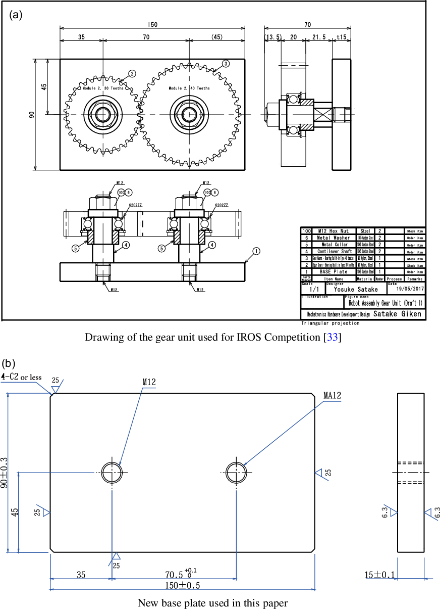
Figure 26. Drawings of the gear unit.
The changes in the base plate are to extend the distance between the two axes by $0.5\ \textrm{mm}$
with an appropriate tolerance specification and to improve the accuracy of the verticality of the screw holes by specifying the machine tapping. Those changes are introduced so that the engagement of the two gears is always smooth within the tolerance of the parts. Note that one should place special orders specifying the tolerance and machine tapping together with the MISUMI order number shown in Table I.
$0.5\ \textrm{mm}$
with an appropriate tolerance specification and to improve the accuracy of the verticality of the screw holes by specifying the machine tapping. Those changes are introduced so that the engagement of the two gears is always smooth within the tolerance of the parts. Note that one should place special orders specifying the tolerance and machine tapping together with the MISUMI order number shown in Table I.

Figure 27. Recognition of washers.
The tolerance of the outer diameter of the fitting part of the shaft is g6, with a minimum of $14.983\ \textrm{mm}$
and a maximum of
$14.983\ \textrm{mm}$
and a maximum of $14.994\ \textrm{mm}$
. The accuracy of the inner diameter of the radial bearings embedded in the two gears is JIS 0 class (equivalent to ISO 492 Normal Class), with a minimum of
$14.994\ \textrm{mm}$
. The accuracy of the inner diameter of the radial bearings embedded in the two gears is JIS 0 class (equivalent to ISO 492 Normal Class), with a minimum of $14.992\ \textrm{mm}$
and a maximum of
$14.992\ \textrm{mm}$
and a maximum of $15.000\ \textrm{mm}$
. Therefore, in theory, the maximum fitting gap is 17 µm (clearance fit) and the minimum is −2 µm (interference fit). When we purchased several parts and actually measured them with a micrometer, however, it turned out that the inner diameter of the bearing was distributed between
$15.000\ \textrm{mm}$
. Therefore, in theory, the maximum fitting gap is 17 µm (clearance fit) and the minimum is −2 µm (interference fit). When we purchased several parts and actually measured them with a micrometer, however, it turned out that the inner diameter of the bearing was distributed between $14.994$
and
$14.994$
and $15.000\ \textrm{mm}$
, and the shaft diameter was distributed between
$15.000\ \textrm{mm}$
, and the shaft diameter was distributed between $14.984$
and
$14.984$
and $14.991\ \textrm{mm}$
. Therefore, the minimum gap is 3 µm and the maximum is 16 µm.
$14.991\ \textrm{mm}$
. Therefore, the minimum gap is 3 µm and the maximum is 16 µm.
Appendix B. Estimation of the recognition error of the vision sensor
As mentioned in Section 2.2.2, the vision sensor used in this paper is a 2-megapixel monochrome camera, and part recognition is achieved using the bundled software (In-Sight Explorer for MELSENSOR Vision). For part recognition, a model for pattern matching is registered by capturing an image of each part in advance, and the coordinates of the part are output by looking for parts in the camera’s field of view whose degree of agreement with the registered patterns exceeds a preset threshold.
First, the target part was placed in the center of the camera’s field of view, and after registering the pattern, recognition of the part position was repeated 10 times without moving the part. The maximum deviation of the position recognition was found to be $0.40\ \textrm{mm}$
for the washer, and the maximum deviation of the orientation was
$0.40\ \textrm{mm}$
for the washer, and the maximum deviation of the orientation was $1.0^{\circ}$
for the nut, respectively. However, this is only an evaluation of the image-based object recognition error under the ideal condition that the model for recognition and the object to be recognized are in exactly the same position.
$1.0^{\circ}$
for the nut, respectively. However, this is only an evaluation of the image-based object recognition error under the ideal condition that the model for recognition and the object to be recognized are in exactly the same position.
Next, we evaluated the recognition error of parts placed at arbitrary positions on the work table, including the calibration error of the camera. First, we examined whether parts could be recognized in the entire area of the work table and confirmed that some parts such as washers failed to be recognized in the peripheral field of view of the camera. This is because the image of a part is distorted by various factors as the part is located further from the image center. For such parts, we solved this problem by registering multiple patterns for recognition as shown in Fig. 27.
Calibration between the camera coordinate system for the vision sensor and the robot coordinate system was performed using the calibration tool provided with the bundled software, according to the following procedure. First, a sheet with a checkerboard pattern for calibration is captured by the vision sensor to recognize the intersection points of the patterns. The center of the hand is moved to the intersection of the recognized patterns, and the pair of the intersection coordinates of the vision sensor and the coordinates of the center of the hand on the robot controller is given to the software. The above is repeated at 20 points on the checkerboard.
After completing the above calibration, the following experiments were conducted to evaluate the final recognition error including the calibration error. The experimental procedure is described below. The target part was the large gear, which needs the highest positioning accuracy for inserting to the shaft.
-
Step 1: Place the large gear at an arbitrary position on the work table;
-
Step 2: Recognize the large gear by vision sensor;
-
Step 3: Move the robot arm to the recognized position and align the large gear using the proposed method;
-
Step 4: The large gear is recognized again by the vision sensor after alignment;
-
Step 5: The difference in the positions of the large gear before and after alignment is used as the final error.
The above procedure was performed at five locations on the work table, resulting in a minimum error of $0.7\ \textrm{mm}$
and a maximum error of
$0.7\ \textrm{mm}$
and a maximum error of $4.4\ \textrm{mm}$
.
$4.4\ \textrm{mm}$
.


