


Introduction
Machine learning and computer vision algorithms are promising techniques to quantify and analyze the ever-increasing amount of scientific image data. Trained neural networks, in particular, have consistently outperformed traditional image analysis methods at a variety of transmission electron microscopy (TEM) image analysis tasks, including identifying clean graphene areas (Sadre et al., Reference Sadre, Ophus, Butko and Weber2021), denoising (Vincent et al., Reference Vincent, Manzorro, Mohan, Tang, Sheth, Simoncelli, Matteson, Fernandez-Granda and Crozier2021), and classifying crystal structures (Aguiar et al., Reference Aguiar, Gong, Unocic, Tasdizen and Miller2019). Neural networks can, in part, associate their high performance with their ability to take on any functional form. These effective functions are influenced by both the training data that dictate the learned features and the chosen neural network architecture.
One common TEM dataset type is an image of nanoparticles on a substrate. These nanoparticle TEM images are often analyzed to extract statistics on nanoparticle size, shape, and crystallinity as nanoparticle function is commonly tied to its structure. Additionally, in situ TEM videos create stacks of images that need to be accurately analyzed to quantify nanoscopic and atomic-scale nanoparticle changes under reaction conditions. Under high enough magnification, these TEM images provide insights into the atomic structure of a nanoparticle, but it becomes difficult to develop analytic methods that can reliably identify these nanoparticles because there are multiple factors that contribute to nanoparticle contrast. Neural networks, on the other hand, can accurately identify nanoparticles at both low and high magnification regimes (Groschner et al., Reference Groschner, Choi and Scott2021; Yildirim & Cole, Reference Yildirim and Cole2021). However, due to the variety of image features in TEM images that change depending on microscope magnification, neural networks often need to be trained to detect image features specific to a given TEM image dataset.
When choosing a neural network, it is unclear whether the same neural network architectures that work well for natural images (i.e. images of the natural world) are also ideal for TEM images. Large labeled datasets of natural images have been a key factor to the success of modern neural networks, allowing the traditional computer vision community to train large networks which can capture more complex behavior and deliver higher performance (Sun et al., Reference Sun, Shrivastava, Singh and Gupta2017). TEM and other scientific data streams, on the other hand, are often either much smaller or more expensive to label. These smaller datasets necessitate either networks with fewer trainable parameters and/or utilizing networks that are pre-trained on much larger datasets of natural images (Akers et al., Reference Akers, Kautz, Trevino-Gavito, Olszta, Matthews, Wang, Du and Spurgeon2021). Additionally, natural images and TEM images are inherently different in various image characteristics, including the number of channels, feature sizes, and feature complexity. Given these differences, it would benefit the microscopy community to build intuition as to how these TEM image features are reflected in neural network architecture and hyperparameter choices. Narrowing down potential network architectures for TEM images would also reduce development time and lower the barrier to entry for training neural networks on a custom TEM image analysis task.
Recent literature has shown that a neural network's receptive field is influential in improving network performance when extending to new datasets, particularly those different from natural images. The receptive field of a network is the theoretical maximal area of the input image that the network can use to make its final decision. The receptive field is affected by the number, order, and types of layers in a neural network as well as their hyperparameters like filter and stride size, and can be calculated by the following equation:
 $${\rm RF} = \sum_{\ell = 1}^{L}\left[( k_\ell -1) \prod_{\,j = 1}^{\ell-1}s_j \right] + 1,\; $$
where L is the number of layers, k ℓ is the filter size of the ℓth layer, and s j is the stride of the jth layer (Araujo et al., Reference Araujo, Norris and Sim2019). Modifying the receptive field to account for dataset-specific feature sizes has lead to increased performance in acoustic scene classification (Koutini et al., Reference Koutini, Eghbal-Zadeh, Dorfer and Widmer2019), ultrasound image segmentation (Behboodi et al., Reference Behboodi, Fortin, Belasso, Brooks and Rivaz2020), and high-resolution TEM image denoising (Vincent et al., Reference Vincent, Manzorro, Mohan, Tang, Sheth, Simoncelli, Matteson, Fernandez-Granda and Crozier2021). Specifically with TEM images, it has been suggested that the receptive field needs to account for the larger length scales of the features of interest (Horwath et al., Reference Horwath, Zakharov, Mégret and Stach2020), and by increasing the receptive field accordingly, researchers were able to achieve much better denoising performance (Vincent et al., Reference Vincent, Manzorro, Mohan, Tang, Sheth, Simoncelli, Matteson, Fernandez-Granda and Crozier2021). However, given the numerous factors that contribute to network performance and the “black-box” nature of neural networks, it is difficult to attribute exactly which neural network features, or even dataset features, affect performance the most.
In this paper, we systematically explore how both neural network architecture and training dataset features affect neural-network-based analysis of nanoparticle TEM images. On the architecture side, we study how performance changes as we independently vary network receptive field and complexity, both of which are hypothesized to affect network performance but are often coupled together. Using curated TEM image datasets with controlled acquisition and sample parameters, we evaluate the role of changing nanoparticle contrast conditions on neural network performance. By developing an understanding of how neural network architecture and dataset features interplay with one another, we can move toward informed decisions as to how to create neural networks that analyze TEM images.
As an example, we focus on the task of nanoparticle segmentation, or pixel-wise classification of the nanoparticle from the amorphous background. Segmentation is useful for unraveling network behavior as it naturally identifies image regions where the neural network incorrectly interprets the image. As each pixel is considered an independent decision and image areas can be used to train multiple pixels, segmentation also does not require a massive amount of acquired images to accurately train a deep neural network, given large-enough images. From an application standpoint, segmentation maps are also a useful first step for further size analysis (Yildirim & Cole, Reference Yildirim and Cole2021), nanoparticle tracking (Yao et al., Reference Yao, Ou, Luo, Xu and Chen2020), and nanoparticle classification (Groschner et al., Reference Groschner, Choi and Scott2021); therefore, our results have the potential to improve automated data analysis pipelines for high throughput and in situ TEM nanoparticle datasets.
Materials and Methods
Dataset Acquisition
2.2 nm Au nanoparticles with citrate ligands were purchased from Nanopartz. 5, 10, and 20 nm Au nanoparticles capped with tannic acid were purchased from TedPella. To create the TEM sample, 5 μL of the nanoparticle solution was dropcasted onto ultrathin carbon TEM grids from TedPella, allowed to rest for about 5 min, and then excess liquid was wicked off with a Kimwipe.
High-resolution TEM images of the 2.2, 5, and 10 nm Au nanoparticles were acquired using an aberration-corrected TEAM 0.5 TEM at 300 kV. High-resolution images were 4096 × 4096 pixels in size at an approximate dosage of 423 e/Å2. Low-resolution TEM images of 20 nm Au nanoparticles were taken with a non-aberration-corrected TitanX TEM at 300 kV. Low-resolution images were 2048 × 2048 pixels in size at an approximate dosage of 16 e/Å2.
Dataset Creation
Each image was manually segmented and labeled using LabelBox. For preprocessing, pixel outliers from x-rays were detected and removed, and then each image was standardized (mean set to 0 and standard deviation set to 1). Images were then split up into 512 × 512 pixel patches to reduce memory requirements during training. Patches that only consisted of amorphous background were removed from the dataset to avoid class imbalance issues during training. Dataset characteristics are summarized in Table 1, with dataset size referring to the number of unique patches.
Table 1. Datasets Used in this Paper.

Dataset size refers to the number of unique 512 × 512 pixel patches before augmentation.
The patches were then split 70-10-20 into training, validation, and test sets, ordered such that patches from the same image were not likely to be in both the training and test sets. Each set was then augmented with the 8 dihedral transformations, and then randomly shuffled.
Computational Framework
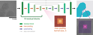
Our network architecture is a UNet structure constructed with residual blocks. The UNet architecture is commonly used in image segmentation, consisting of a contracting encoder arm and an expansive decoder arm, with the two arms mirroring each other in structure and connected to one another via skip connections (Fig. 1) (Ronneberger et al., Reference Ronneberger, Fischer and Brox2015). Each arm is composed of N residual blocks connected by max pooling layers which downsample the residual block output features. The residual block structure consists of a convolutional layer, followed by a batch norm layer, then a rectified linear unit (ReLU) layer, and then repeated. An additive skip connection connects the input of the residual block to the final ReLU layer, creating a structure where the first five layers are learning the “residual” between the input and the output (He et al., Reference He, Zhang, Ren and Sun2016). We set the number of filters in each convolutional layer to be constant for each residual block, starting with four filters and doubling with each new residual block. The size of each convolutional filter is kept constant at 3 × 3 pixels with a stride of 1 pixel.

Fig. 1. Overview of the UNet-based neural network architectures. We track segmentation performance as we vary the receptive field by either changing the number of residual blocks, N = 2, 3, 4, and/or the max pooling kernel size, k = 2, 4, 8. The purple shaded boxes show example receptive fields for a single pixel decision.
To change the receptive field without modifying the number of trainable parameters, we vary the max pooling filter size (and the corresponding upsampling filter size) to be either k = 2, 4, or 8 pixels. The max pooling operation outputs the maximum value in a k × k area and does not have any trainable parameters. Therefore, we can construct networks that share the same number of parameters (i.e. complexity) but have varying receptive fields. As the stride (s) of the max pooling layer scales with the filter size, this leads to a much wider range of receptive fields (see equation (1)) than simply modifying filter size. We restrict our study to architectures with receptive fields smaller than the total image size and have provided the calculated receptive fields for all network architectures in Supplementary Table S1. In this paper, we present the receptive field size in nanometers rather than pixels to better contextualize the receptive field size in relation to nanoparticle features.
To understand how network complexity affects our results, we utilize three architectures with different numbers of residual blocks from N = 2–4, with the total number of trainable network parameters shown in Table 2. More complex, or deeper, neural networks perform better as deeper architectures can better construct functions that capture nonlinear image features. By comparing a lightweight network (N = 2) against a more traditional deep UNet structure (N = 4) at similar receptive field values, we can identify to what extent more complexity is needed.
Table 2. Neural Network Architecture Details.

The three architectures used in this paper and their number of trainable parameters.
Network Training and Evaluation
We set all training hyperparameters to be constant between models, such that the only differences between networks are the architectural choices. The augmented training set, the order in which the network sees batches of images, and the initialized weights are also kept constant when comparing across different neural network architectures. The validation set is used to determine the number of training epochs for each dataset to prevent overfitting; networks are trained for either 100 or 150 epochs. Training using early stopping (see Supplementary Fig. S1) did not affect results.
Networks are trained with a cross-entropy loss function which pixel-wise penalizes the network for predictions far from ground truth, and with the Adam optimizer using a learning rate of 10−4. Each network is trained five times with different initialized weights, and the reported performance is the average and standard deviation of those five runs on the test set. Training was done either locally on a Nvidia RTX3090 GPU or on a cluster with a Nvidia K80 GPU.
Segmentation performance is evaluated by the dice score which measures the similarity between two images and quantifies it between 0 and 1, with 1 being a perfect replication of the ground truth label. We are primarily interested in the networks’ ability to identify nanoparticles, and so we treat this as a binary prediction, and calculate the dice score as follows:
 $$D = {2\vert X \cap Y\vert \over \vert X\vert + \vert Y\vert },\; $$
where X is the predicted segmentation, Y is the ground truth, and the | : | operation calculates the number of pixels classified to be a nanoparticle. Since there are only two classes (nanoparticle and background), the dice score penalizes undersegmentation or false negatives (missing an area that is labeled as nanoparticle) more than oversegmentation or false positives (classifying background as nanoparticle) (see Supplementary Material for proof). This makes the dice score a useful metric for nanoparticle segmentation because missing nanoparticle regions is a more dire consequence as false positives can be eliminated later on in an image analysis pipeline. The dice score can be calculated in two ways: either using the binary predictions (hard dice score) or using the predicted probabilities of each class (soft dice score). In this paper, we use the hard dice score to measure performance but also report the soft dice scores in the Supplementary Material (Figs. S2, S3, and S4), which give a better indication of how confident a network is in its prediction.
Fourier Filtering
Traditionally, nanoparticle segmentation in high-resolution TEM images is done via Fourier filtering, which then can be used as a benchmark for performance (Groschner et al., Reference Groschner, Choi and Scott2021). Fourier filtering identifies nanoparticle regions using the lattice fringes from the crystalline nanoparticles; these periodic image features result in a localized signal in Fourier space, which can be filtered and transformed back to real space to highlight nanoparticle regions. To Fourier filter the high-resolution TEM images, we fast Fourier transform (FFT) the image and then apply a bandpass filter to select the dominant Bragg peaks. The bandpass location and width are chosen such that they capture the dominant first-order Fourier peaks in the FFT. The masked FFT is then inverted to obtain an image that highlights the areas that corresponded to the Bragg peaks, then blurred with a Gaussian filter (9 pixel filter size) to smooth out the resulting lattice fringe. For each Fourier filtered image, all pixels above a threshold value determined by Otsu's method are classified as nanoparticle.
Dilated Convolution
Another strategy to increase receptive field without modifying network complexity is to dilate the convolution filters, which increases the filter size without changing the number of filter pixels. Dilation is quantified by a parameter α which sets the spacing between pixels within the convolution filter. As noted by Araujo et al. (Reference Araujo, Norris and Sim2019), to calculate the receptive field with dilated convolution layers, one just replaces the filter size k ℓ in equation (1) with α(k ℓ − 1) + 1. We set the dilation parameter to be constant within each residual block, and the exact architectural parameters are given in Supplementary Table S2.
Results
From an image analysis perspective, there are two regimes of TEM imaging: low-resolution and high-resolution. In low-resolution TEM images, nanoparticles are primarily identified using image contrast; because of amplitude contrast, nanoparticles appear dark against a bright background (Fig. 2a). On the other hand, in high-resolution TEM images, nanoparticle amplitude and phase contrast lead to slightly darker regions with visible lattice fringes; nanoparticles are then distinguished from the background using both image contrast and image texture (Fig. 2b). Low-resolution TEM images, then, require a network that can detect changes in image contrast, while high-resolution TEM images need a network that can both detect macroscopic changes in image contrast and distinguish between amorphous and crystalline textures. Therefore, networks trained for these distinct image tasks will likely behave differently and have distinct characteristics.

Fig. 2. Receptive field dependence on low-resolution and high-resolution TEM images. (a,b) Example images and ground truth labels from the (a) low-resolution TEM image dataset of 20 nm Au nanoparticles and (b) high-resolution TEM image dataset of 5 nm Au nanoparticles. (c,d) Segmentation performance as receptive field is increased for the (c) low-resolution dataset and (d) the high-resolution dataset. Results are plotted for three different network complexities.
We first examine how receptive field affects networks that are trained to segment low-resolution TEM images. We train three neural network architectures with different complexities (N = 2, 3, or 4) on a 20 nm Au nanoparticle dataset and vary the receptive field for each architecture. As the receptive field is increased, segmentation performance remains high, with only a slight decrease in performance at large receptive fields (Fig. 2c). For a simple 2-residual block network, the dice score is 0.974 ± 0.001 when the receptive field is 5.5 nm or a quarter of the nanoparticle diameter, and then becomes 0.963 ± 0.007 when the receptive field is 48.7 nm, or over twice the average nanoparticle size. Increasing complexity leads to a slight increase in performance, with the 3-residual block and 4-residual block networks outperforming the 2-residual block network at all receptive field values.
On the other hand, when we repeat the same training but with high-resolution TEM images of 5 nm nanoparticles, we notice a stronger dependence on receptive field (Fig. 2d). For this contrast and texture-based segmentation task, performance increases with larger receptive fields but then plateaus at a certain receptive field size. Again, for a 2-residual block network, the dice score starts at 0.727 ± 0.004 for networks with a small receptive field of 0.95 nm, but then increases to 0.783 ± 0.007 for networks with the same number of parameters but larger receptive field of 8.4 nm. This plateauing trend is seen in both the 2-residual block and 3-residual block networks, but not for the 4-residual block networks as it starts off with a receptive field around the plateau region. In contrast to the low-resolution TEM images, both complexity and receptive field influence segmentation performance in high-resolution TEM images. Given the same receptive field, a more complex network may perform better. However, a simpler network with a large-enough receptive field can outperform a more complex network with a smaller receptive field. This suggests that receptive field is an important consideration when working with high-resolution TEM images.
This receptive field dependence is seen in all high-resolution TEM images, regardless of nanoparticle size. We repeat the receptive field experiment on three new high-resolution TEM datasets taken at the same magnification, each of either 2.2, 5, or 10 nm Au nanoparticles on an ultrathin carbon substrate. In all three datasets, segmentation performance increases then plateaus with a larger receptive field, though the dependence becomes less noticeable as nanoparticle size increases (Fig. 3). Interestingly, the receptive field value at which performance starts to plateau is greatest for the small (2.2 nm) nanoparticles, requiring a receptive field much greater than the average diameter of the nanoparticles for peak performance. We hypothesize that the inverse relationship between nanoparticle size and necessary receptive field is due to the greater nanoparticle contrast as diameter (and, therefore, thickness) increases. By comparing the histograms of pixel values in the three datasets, we see that the contrast between nanoparticle and background increases with larger nanoparticle size. As receptive field is less important in high contrast images, as noted in Figure 2c, it is likely that as the nanoparticles become easier to identify, the network requires less spatial information to gauge changes in contrast, and therefore, there is less dependence on the receptive field.

Fig. 3. Receptive field dependence in high-resolution TEM datasets of 2.2, 5, and 10 nm Au nanoparticles. For each dataset, we show a sample image from the test set, the pixel value histograms of the training set separated by label, and the segmentation performance as a function of receptive field and network complexity. The vertical lines in the histograms denote median values.
In addition to modifying the pooling layers, there are multiple strategies that can modify receptive field, including changing hyperparameters like filter size, stride, and/or number of layers. To further demonstrate that our results are not limited to this pooling strategy, we repeat our receptive field investigation on the high-resolution TEM images of 5 nm Au nanoparticles but now vary the dilation parameter of our convolutional filters (Fig. 4a) instead of the max pooling kernel size. As seen in Figure 4b, as receptive field is increased using dilated convolution, we observe an increase in segmentation performance, followed by a plateau around 5 nm, similar to our results on the same dataset using max pooling (Fig. 2d). Quantitatively, both methods similarly saturate around 0.79 in the hard dice score. The similarities in behavior despite technical differences in the neural network architecture further cement that receptive field is influential to performance.

Fig. 4. Neural network performance when increasing the receptive field using dilated convolutions. (a) Schematic depicting how dilation changes the convolution filters. (b) Segmentation performance on high-resolution TEM images of 5 nm Au nanoparticles when receptive field is increased using dilated convolutions for three different network complexities.
Discussion
In contrast-based low-resolution TEM images, the receptive field does not seem to be an important factor in segmentation performance. The network does not show any increase in performance as it changes from a receptive field smaller than half of the nanoparticle diameter to much larger than the nanoparticle diameter. These results suggest that for these higher-contrast TEM images, neural networks do not need contextual information about nanoparticle size in order to perform well.
The slight decrease in performance with increasing receptive field can be attributed to aliasing effects from the larger max pooling filters. Since max pooling takes the maximal value in a k × k pixel area (and its corresponding upsampling procedure repeats the maximal value in a k × k area), we lose fine detail information as k increases. This can be qualitatively seen in Figure 5, which shows how three 2-residual-block networks, which only differ by their receptive fields, perform when segmenting three test images. We see that qualitatively, all three networks correctly segment the nanoparticles, but the results from the 48.7 nm receptive field network have rough, blockier edges, which we attribute to the large max pooling filter size. Note that in practice, when optimizing for high performance on a segmentation task, max pooling is often kept to k = 2 to avoid these blocky artifacts.

Fig. 5. Example segmentation results on low-resolution TEM images of 20 nm Au nanoparticles for a 2-residual-block network with different receptive fields, with the hard dice score values displayed in the upper right corner. Colored squares superimposed on the TEM image in (a) outline the relative size of the receptive fields of the three networks.
High-resolution TEM images, however, quantitatively and qualitatively show a significant difference as receptive field is increased. In Figure 6, we again compare segmentation results from three 2-residual-block networks of various receptive fields. For an ideal high-resolution TEM image in which the lattice fringes are visible for the entire nanoparticle (Fig. 6a), all three networks perform equally well at identifying the nanoparticle region. The network with the smallest receptive field occasionally misclassifies parts of the background region as nanoparticle, but the larger receptive field networks do not make the same mistake. The results from the 8.4 nm receptive field network also show the same blocky artifacts seen in the 48.7 nm receptive field network in Figure 5; since these two networks have the exact same architecture, we further confirm that these artifacts are from the max pooling filter size.

Fig. 6. Example segmentation results on high-resolution TEM images of 5 nm Au nanoparticles for a 2-residual-block network with different receptive fields, with the hard dice score values displayed in the upper right corner. Colored squares superimposed on the TEM image in (a) outline the relative size of the receptive fields of the three networks.
The small receptive field network also misclassifies nanoparticle regions where there are fainter or no visible lattice fringes, but larger receptive field networks are able to segment those same regions correctly (Figs. 6b, 6c). By human eye, these regions are still identified as part of the nanoparticle due to both the slight change in contrast from the background and contextual information about the nanoparticle shape (i.e. spherical and convex). This again supports our findings in Figure 3 that larger receptive fields enable the better segmentation of low-contrast nanoparticles.
These misclassified nanoparticle regions, denoted as false negatives, happen to be areas that Fourier filtering, a purely texture-only image segmentation technique for high-resolution TEM images, also miss. To compare, we manually Fourier filter the non-augmented test images and compare their false negative regions against the false negative regions from the 0.95, 2.6, and 8.4 nm receptive field networks (Figs. 7a, 7b). All segmentation techniques struggle with nanoparticle edges, but the false negative regions from Fourier filtering look more similar to the 0.95 nm receptive field results than the 8.4 nm receptive field results. For most of the test images, the smaller receptive field network has false negatives most similar to Fourier filtering (see Supplementary Fig. S8 for statistics), suggesting that smaller receptive field networks may be learning a function similar to Fourier filtering. We hypothesize that the spatial constraints force the neural network to learn the simplest way to segment with limited contextual clues—by identifying lattice fringes. Once that spatial constraint is expanded, the network learns to incorporate macroscopic contrast information and therefore improves performance.

Fig. 7. Comparing false negative regions in UNet segmentation results against false negative regions from Fourier filtering. (a,b) Example test images and their corresponding false negative maps after segmentation via Fourier filtering and three 2-residual-block networks with varying receptive fields.
If small receptive fields lead to trained neural networks with results similar to Fourier filtering, then we also have an alternative explanation as to why small receptive field networks still perform well on large (10 nm) Au nanoparticles. When using Fourier filtering to segment, the 10 nm nanoparticle dataset has the highest dice score (Supplementary Table S3), likely because it has more areas with visible lattice fringes. Therefore, we might see a smaller increase in performance with larger receptive fields because there are fewer areas with faint/no visible lattice fringes, which are often the areas that small receptive field networks misclassify.
Similar to prior denoising results, we also find that the receptive field needs to account for the larger (in pixel size) atomic image features in high-resolution TEM images (Vincent et al., Reference Vincent, Manzorro, Mohan, Tang, Sheth, Simoncelli, Matteson, Fernandez-Granda and Crozier2021). Given the differences in image task (denoising vs. segmentation) and network architecture but similar results with respect to receptive field, we conclude that receptive field is an important consideration when working with high-resolution TEM images. Our results suggest that receptive field may be limiting performance in lower complexity networks. We not only observe plateauing behavior when only increasing the receptive field, but also that the increase in performance by using a more complex network is mostly from differences in the receptive field, particularly in images with low nanoparticle contrast. As seen in Figures 2d and 3, the 3-residual-block networks can reach similar performances to 4-residual-block networks once their receptive fields are about the same. However, receptive field is not the sole determinant of network performance. As seen in Figure 3, increasing the receptive field of the 2-residual-block network does not reach equal performance to that of the 3- and 4-residual-block networks. Additionally, our results suggest that the ideal receptive field size is related to the degree of nanoparticle contrast, not the number of atoms in the receptive field nor the nanoparticle size. Taken together, our findings suggest that the receptive field should be considered in addition to network complexity, especially for high-resolution TEM images with a low nanoparticle contrast.
In practice, the choice of how to increase receptive field will depend on the image analysis task and the acceptable types of image artifacts. By qualitatively comparing performance between a neural network with increased receptive field using max pooling versus dilated convolution, we see that these different strategies lead to similar segmentation results but different image artifacts at the nanoparticle edges (Fig. 8). Both networks misclassify similar regions, as seen in the bottom right of the test image in Figure 8a and bottom left of the test image in Figure 8b, suggesting that the two networks are identifying similar features. If we zoom in (Fig. 8c), the larger max pooling kernel size leads to blocky edges, as noted before, while dilation leads to gridding artifacts near the nanoparticle edges which make it difficult to identify the exact location of the edge. Therefore, for a dense image analysis task like nanoparticle segmentation where informations about the edges are important, one would likely avoid using max pooling or dilation to increase receptive field but instead utilize average pooling/bilinear upsampling, larger convolution filters, more layers, or other novel ideas being proposed in computer vision (Wang & Ji, Reference Wang and Ji2021). On the other hand, for a classification task which associates an entire image with a label, the choice in strategy may not matter as much.

Fig. 8. Comparison of segmentation results for a ~2.6 nm receptive field using either max pooling or dilation. (a,b) Two test images from the high-resolution dataset of 5 nm Au nanoparticles and their respective segmentation results. (c) A zoom-in of the test image in (b) highlights the edge artifacts from both max pooling and dilation.
Finally, we note that the receptive field reported here is the theoretical maximal area that contributes to the final decision. In reality, the receptive field is not equally weighted and the effective receptive field, or the area that significantly influences the decision, is smaller (Luo et al., Reference Luo, Li, Urtasun and Zemel2016). The effective receptive fields of our trained UNets are dominated by pixels nearby the decision pixel due to skip connections, even as the maximal receptive field is increased (Supplementary Fig. S9). Further examination shows that the edges of the larger receptive field networks still contribute, and we hypothesize that these large receptive field networks maintain their high performance because they incorporate both local and global information.
Summary
In summary, by systematically modifying the receptive field for various combinations of neural network complexities and TEM image datasets, we have identified how neural network constraints affect nanoparticle segmentation. Our results suggest that while low-resolution, contrast-based nanoparticle TEM images seem to be insensitive to the size of a neural network's receptive field, high-resolution contrast- and texture-based nanoparticle TEM images require neural networks with a large-enough receptive field in order to perform well. Receptive field is especially important when segmenting small and/or low-contrast nanoparticle regions, as only large-enough receptive fields can detect the subtle change in contrast. Our results provide intuition as to how neural network architecture choices affect TEM image analysis and guidance for microscopists interested in customizing neural network architectures for their datasets.
Availability of data and materials
All datasets and ground truth labels acquired for this paper are available on Zenodo: https://doi.org/10.5281/zenodo.6419024. Code and Jupyter notebooks are available at https://github.com/ScottLabUCB/HRTEM-Receptive-Field.
Supplementary material
To view supplementary material for this article, please visit https://doi.org/10.1017/S1431927622012466.
Acknowledgments
This work was primarily funded by the U.S. Department of Energy in the program “4D Camera Distillery: From Massive Electron Microscopy Scattering Data to Useful Information with AI/ML.” Imaging was done at the Molecular Foundry, which is supported by the Office of Science, Office of Basic Energy Sciences, of the U.S. Department of Energy under Contract No. DE-AC02-05CH11231. Part of this research used the Savio computational cluster provided by the Berkeley Research Computing program at the University of California, Berkeley (supported by the UC Berkeley Chancellor, Vice Chancellor for Research, and Chief Information Officer).
Competing interests
The authors declare that they have no competing interest.


 Open access