


1. Introduction
Common vortical wake flows as generated by aircraft, submarines, and flying and swimming animals are dominated by coherent vortical structures with tube- or ring-like geometries. The evolution of these vortices determines the overall wake dynamics, which affects ambient mixing (Crowe, Chung & Troutt Reference Crowe, Chung and Troutt1988; Miake-Lye et al. Reference Miake-Lye, Martinez-Sanchez, Brown and Kolb1993), sound generation (Powell Reference Powell1964; Bridges & Hussain Reference Bridges and Hussain1987), the behaviour of trailing bodies (Nelson & Jumper Reference Nelson and Jumper2001), and the phenomenon of cavitation (Arndt Reference Arndt2002; Chang et al. Reference Chang, Choi, Yakushiji and Ceccio2012; Agarwal et al. Reference Agarwal, Ram, Lu and Katz2023). Given the high Reynolds number of these vortices, they are susceptible to instabilities arising from small perturbations (Ash & Khorrami Reference Ash and Khorrami1995). Typical perturbations arise from the presence of ambient or self-induced strain fields (Moore & Saffman Reference Moore and Saffman1975; Widnall & Tsai Reference Widnall and Tsai1977; Arendt & Fritts Reference Arendt and Fritts1998), as well as variations in the internal shape and structure of the vortex when it is shed from a surface in motion (Leweke et al. Reference Leweke, Quaranta, Bolnot, Blanco-Rodríguez and Le Dizés2014; Abraham, Castillo-Castellanos & Leweke Reference Abraham, Castillo-Castellanos and Leweke2023). The flow response to such perturbations depends on various features including perturbation wavelength, amplitude, shape of the vortex, and the circulation-based Reynolds number.
Though the stability of vortical structures to centreline perturbations and ambient strain fields has been assessed for many decades using linear and nonlinear stability analyses, numerical simulations and experiments, the effect of core size perturbations has not received as much attention. For rectilinear vortices, such perturbations can be understood as  $m=0$ Kelvin waves (Thomson Reference Thomson1880), and previous work has found that variations in the core size lead to the generation of twist waves that propagate along the vortex core (Melander & Hussain Reference Melander and Hussain1994; Arendt, Fritts & Andreassen Reference Arendt, Fritts and Andreassen1997; Samuels Reference Samuels1998; Moet et al. Reference Moet, Laporte, Chevalier and Poinsot2005). In Moet et al. (Reference Moet, Laporte, Chevalier and Poinsot2005), it was shown numerically that at sufficiently high Reynolds number, the collision of such twist waves of opposite signs leads to a drastic local increase of the vortex core, a process denoted as vortex bursting. These simulation results qualitatively match experimental observations on aircraft trailing wakes reported in Spalart (Reference Spalart1998). In van Rees (Reference van Rees2020) and Ji & van Rees (Reference Ji and van Rees2022), we investigated the mechanics of vortex bursting more carefully using direct numerical simulations of vortex tubes with varying initial core perturbation amplitudes at Reynolds numbers up to $10^4$. The analysis showed that the dynamics and features of vortex bursting initially resemble the head-on collision of two swirling vortex rings, but that the topological constraints of the vortex lines arrest, and eventually reverse the radial expansion of the core. Long-time simulations showed that repeated bursting events lead to significant increase in energy dissipation in the wake, compared to the purely viscous decay of an unperturbed Lamb–Oseen vortex tube (Ji & van Rees Reference Ji and van Rees2022).
The previous results highlighted the dynamics of vortex bursting on ‘idealized’ vortices with no intrinsic centreline dynamics, as the centreline remains straight for all time. In these results, the flows remained largely axisymmetric during the bursting process. However, real wake vortices are commonly characterized by curved centrelines because the generating surface undergoes small transient motions due to fluid–structure interaction or external actuation, or because the vortex itself deforms dynamically in the presence of an ambient strain field. It is therefore of interest to assess how the fundamental mechanisms and consequences of vortex bursting, as discussed in earlier research, change when the centrelines of vortices deviate from the idealized straight-line scenario. This assessment can be used to understand the ubiquity and importance of vortex bursting in the type of flows described above.
From a vortex dynamics perspective, curvature and torsion of vortex lines lead to a self-induced strain field that can substantially change the dynamic evolution and stability of the flow compared to straight vortices (Betchov Reference Betchov1965; Widnall Reference Widnall1972). Starting with helical vortices, existing studies on their stability concentrate mainly on the effects of centreline displacements for helical geometries where the core size is much smaller than the radius of the helix. Under these circumstances, instabilities are characterized as either long-wave or short-wave instabilities, depending on whether the wavelength of perturbation is large or small compared with the core size. The former leads to local pairing or leap-frogging of neighbouring turns of the helix (Widnall Reference Widnall1972; Leweke et al. Reference Leweke, Quaranta, Bolnot, Blanco-Rodríguez and Le Dizés2014). The latter manifests as short-wavelength displacement of the vortex centreline, in a sinusoidal or helical shape (Leweke et al. Reference Leweke, Quaranta, Bolnot, Blanco-Rodríguez and Le Dizés2014). The evolution of helical vortices can also be framed from the perspective of helicity. Thin vortex bundles, in isolation, consist of vortex lines winding around some common centreline. The total helicity of the bundle can be decomposed geometrically into a component attributable to the writhe of the centreline, and one to the twist of the vortex lines around the centreline (Moffat & Ricca Reference Moffat and Ricca1992). Though the evolution of twist and writhe have been considered in the presence of an external strain field (Scheeler et al. Reference Scheeler, van Rees, Kedia, Kleckner and Irvine2017), the helicity evolution of helical vortex tubes undergoing core instabilities has not been studied extensively.
Similar to helical vortices, the vortex ring is an archetypal vortical structure that arises in a variety of fluid flows. The curvature of the ring has a significant effect on the stability to small perturbations of the centreline (Maxworthy Reference Maxworthy1972; Widnall & Sullivan Reference Widnall and Sullivan1973; Widnall, Bliss & Tsai Reference Widnall, Bliss and Tsai1974). Both theoretical and numerical analyses show that curvature can lead to deformation of vortex cores resulting in short-wave instabilities, such as the elliptic instability and curvature instability for vortex rings without swirl (Hattori & Fukumoto Reference Hattori and Fukumoto2003; Fukumoto & Hattori Reference Fukumoto and Hattori2005) and with swirl (Blanco-Rodríguez & Le Dizés Reference Blanco-Rodríguez and Le Dizés2016, Reference Blanco-Rodríguez and Le Dizés2017; Hattori, Blanco-Rodríguez & Le Dizés Reference Hattori, Blanco-Rodríguez and Le Dizés2019). Besides these previous studies on the effect of centreline perturbations, recently Shen et al. (Reference Shen, Yao, Hussain and Yang2023) numerically studied vortex rings with initial differential twist distributions at a circulation-based Reynolds number  $2000$. Their work shows that the twist waves propagate consistent with a Burger's-like equation involving the local twist rates. They further show that bursting takes place when the two peaks of the local twist get close and develop into a shock-like discontinuity, and that bursting can similarly be triggered from initial core size perturbations on the rings. However, their work does not analyse the bursting mechanics and long-time flow evolution in detail.
In this work, we investigate numerically the bursting process and the stability of helical vortices and vortex rings with initial core size variations. We confine ourselves to cases that can be considered small variations of straight-line vortices. For helical vortices, this means considering centrelines with small radius-to-pitch ratios, where no mutual induction instabilities between the adjacent helical turns are expected (Widnall Reference Widnall1972; Fukumoto & Miyazaki Reference Fukumoto and Miyazaki1991; Leweke et al. Reference Leweke, Quaranta, Bolnot, Blanco-Rodríguez and Le Dizés2014). For vortex rings, our focus is on rings with a large radius-to-core ratio. For all cases, the Reynolds number is  $5000$, which is sufficiently large to trigger bursting from reasonably small initial core size perturbation amplitudes. The main aim is to investigate how curved vortex centrelines affect the propagation of twist waves and the bursting events, and how bursting in turn influences the long-time behaviour and stability of the vortex tubes. Although the present study remains an idealized scenario of curved vortex lines with regular pitch and core thickness variations, it considers for the first time the robustness of bursting to the self-induced ambient strain fields associated with curvature and torsion of the vortex. Consequently, it offers insights into the potential impact of vortex bursting in the evolution of common wake flows.
The remainder of this work is structured as follows. First, we explain the numerical method and set-up of helical vortex tubes and vortex rings with initial core size variations in § 2. In § 3, we discuss the results on helical vortices, including the overall evolution, twist wave propagation, bursting process, helicity dynamics, and long-time flow diagnostics. In § 4, we analyse the results on vortex rings with initial core size variations, including the overall flow evolution, bursting process and long-time diagnostics. Finally, we provide our conclusions and outlook in § 5.
2. Numerical method and set-up
2.1. Numerical method
We simulate the three-dimensional (3-D) incompressible Navier–Stokes equations in vorticity–velocity form
 $$\begin{gather} \frac{\partial \boldsymbol{\omega}}{\partial t} + (\boldsymbol{u} \boldsymbol{\cdot} \boldsymbol{\nabla}) \boldsymbol{\omega} = (\boldsymbol{\omega}\boldsymbol{\cdot} \boldsymbol{\nabla})\boldsymbol{u} + \nu\,\nabla^2 \boldsymbol{\omega}, \end{gather}$$
 $$\begin{gather}\nabla^2\boldsymbol{u} =- \boldsymbol{\nabla} \times \boldsymbol{\omega}, \end{gather}$$
where  $\boldsymbol {\omega } = \boldsymbol {\nabla } \times \boldsymbol {u}$ is the vorticity vector, $\boldsymbol {u}$ is the velocity vector, and $\nu$ is the kinematic viscosity. The equations are discretized and evolved using a remeshed vortex method (Koumoutsakos & Leonard Reference Koumoutsakos and Leonard1995; Cottet & Koumoutsakos Reference Cottet and Koumoutsakos2000). The right-hand side of the vorticity equation is discretized on a uniform Cartesian grid with a finite-difference method. Vorticity transport is handled using a set of Lagrangian particles, which are initialized from the grid points at the beginning of each time step, and are advected with the flow. At the end of each time step, the weights of the particles are redistributed back onto the grid using a high-order, moment-preserving interpolation kernel. In this work, we use the sixth-order $M^*_6$ kernel for interpolation between the mesh and particles (Bergdorf Reference Bergdorf2007; van Rees et al. Reference van Rees, Leonard, Pullin and Koumoutsakos2011), together with fourth-order centred finite-difference stencils for the stretching and diffusion terms. The Poisson equation for the velocity field is solved on the Cartesian grid using a fast Fourier transform, where the careful treatment of the Green's function and transformation domain enables the use of arbitrary combinations of free-space and periodic boundary conditions (Hockney & Eastwood Reference Hockney and Eastwood1981; Chatelain & Koumoutsakos Reference Chatelain and Koumoutsakos2010). The equations are integrated in time using a fourth-order Runge–Kutta scheme. The time step is controlled through the Lagrangian CFL criterion that sets the time step inversely proportional to the norm of the velocity gradient tensor. To mitigate the accumulation of discretization errors that could violate the solenoidal nature of the vorticity field, a spectral solenoidal reprojection is performed every ten time steps. The solver is implemented in the Parallel Particle-Mesh library designed for massively parallel computing (Sbalzarini et al. Reference Sbalzarini, Walther, Bergdorf, Hieber, Kotsalis and Koumoutsakos2006). The accuracy of this method has been shown previously by comparing with the pseudo-spectral methods in van Rees et al. (Reference van Rees, Leonard, Pullin and Koumoutsakos2011), and to date the method has been used successfully for a variety of studies on 3-D vortical flows (Bergdorf, Koumoutsakos & Leonard Reference Bergdorf, Koumoutsakos and Leonard2007; van Rees, Hussain & Koumoutsakos Reference van Rees, Hussain and Koumoutsakos2012; Scheeler et al. Reference Scheeler, van Rees, Kedia, Kleckner and Irvine2017), including our previous studies of vortex bursting (van Rees Reference van Rees2020; Ji & van Rees Reference Ji and van Rees2022).
2.2. Set-up
Below, we discuss the initial condition and simulation settings, first for the helical vortex tube and subsequently for the vortex ring.
2.2.1. Set-up for helical vortex tubes with varying core size
The centreline of the vortex tube is defined as a right-handed circular helix with radius  $R$ and pitch $p$ (distance of one complete helical turn), winding around the $z$-axis. The centreline is parametrized using arc length $s$, so that its definition in Cartesian coordinates becomes
 \begin{equation} \boldsymbol{c}(s) = R \cos(\theta(s))\,\hat{\boldsymbol{e}}_x + R \sin(\theta(s))\, \hat{\boldsymbol{e}}_y + p\,\frac{\theta(s)}{2{\rm \pi}}\,\hat{\boldsymbol{e}}_z, \end{equation}
with
 \begin{equation} \theta(s) = \frac{s}{\sqrt{R^2+\left(\dfrac{p}{2{\rm \pi}}\right)^2}} \end{equation}
the angular coordinate varying along the helix.
We construct a helical vortex tube around the centreline using a Gaussian core vorticity profile, where the vortex lines are initially untwisted, and the core size is allowed to vary with  $s$. To do so, we define the unit tangent vector at a point $\boldsymbol {c}(s)$ along the centreline as $\hat {\boldsymbol {e}}_s \equiv {{\rm d}\boldsymbol {c}}/{{\rm d}s}$. The point $\boldsymbol {c}(s)$ and vector $\hat {\boldsymbol {e}}_s$ uniquely define a plane $\mathcal {P}(s)$ normal to the centreline. Each location $\boldsymbol {x}$ in the computational domain lies in one or more of these planes. We identify the closest plane to $\boldsymbol {x}$ by the arc length parameter $\hat {s}{(\boldsymbol {x})}$, defined as $\hat {s}{(\boldsymbol {x})} = \min _{s}|\boldsymbol {x}-\boldsymbol {c}(s)|$, and solved for numerically in practice. Then for each point $\boldsymbol {x}$, we can form a local cylindrical coordinate system $(\hat {\boldsymbol {e}}_s, \hat {\boldsymbol {e}}_{\rho }, \hat {\boldsymbol {e}}_{\phi })$ where $\hat {\boldsymbol {e}}_{\rho } \equiv ({\boldsymbol {x}-\boldsymbol {c}(\hat {s}{(\boldsymbol {x})})})/{|\boldsymbol {x}-\boldsymbol {c}(\hat {s}{(\boldsymbol {x})})|}$ and $\hat {\boldsymbol {e}}_{\phi } \equiv \hat {\boldsymbol {e}}_{s} \times \hat {\boldsymbol {e}}_{\rho }$. The vorticity components are defined in this local orthonormal coordinate system as
 \begin{equation} \boldsymbol{\omega}(\boldsymbol{x}) = \frac{\varGamma_0}{{\rm \pi} \sigma(\hat{s}{(\boldsymbol{x})})^2}\exp\left( -\frac{\rho(\boldsymbol{x})^2}{\sigma(\hat{s}{(\boldsymbol{x})})^2}\right) \left[\frac{\rho(\boldsymbol{x})}{\sigma(\hat{s}{(\boldsymbol{x})})}\left.\frac{{\rm d}\sigma}{{\rm d}s}\right|_{s=\hat{s}{(\boldsymbol{x})}}\hat{\boldsymbol{e}}_{\rho} + \hat{\boldsymbol{e}}_s\right]\!, \end{equation}
where  $\rho (\boldsymbol {x}) = |\boldsymbol {x} - \boldsymbol {c}(\hat {s}{(\boldsymbol {x})})|$, $\varGamma _0$ is the circulation of the vortex tube, and $\sigma (s)$ is a function controlling the size of the vortex core.
Here, we choose  $\sigma (s)$ so that the core exhibits an isolated, sinusoidal bump of wavelength $\lambda$ where the core size increases smoothly from $\sigma _{min}$ to $\sigma _{max}$ and back. The remainder of the vortex tube, spanning a distance $p - \lambda$ along the $z$-axis, has constant core size $\sigma _{min}$. We define the non-dimensional initial core size variation as $A = \sigma _{max}/\sigma _{min}$, and the average core size parameter as $\sigma _0 = \frac {1}{2}(\sigma _{max} + \sigma _{min})$. A schematic of the helical vortex tube is shown in figure 1.

Figure 1. Sketch of the projection of the initial helical vortex tube on the  $r\unicode{x2013}z$ plane.
In this work, we consider helical vortex tubes with small radius-to-pitch ratios  $0.02 \leq R/p \leq 0.0625$ and core size ratios $1 \leq A \leq 4.3$. For all cases, we fix $p = 20 \sigma _0$ and $\lambda = 10\sigma _0$. The circulation-based Reynolds number is fixed to be $Re_{\varGamma } = {\varGamma _0}/{\nu } = 5000$ for all cases considered. The rectangular computational domain has size $L_x \times L_y \times L_z$ and has periodic boundary conditions in the $z$ direction, and is unbounded in the $x$ and $y$ directions (Chatelain & Koumoutsakos Reference Chatelain and Koumoutsakos2010). There is one complete helical turn inside the domain, i.e. $p = L_z$, and the transverse extent of the domain $L_x = L_y$ varies with the radius of the helical tube. The parameters for all the cases are summarized in table 1. To ensure the accuracy of each simulation, we calculate the instantaneous errors in the effective viscosity for each simulation (van Rees et al. Reference van Rees, Leonard, Pullin and Koumoutsakos2011), which peaks at $1.7\,\%$ across all cases. Based on our previous experience, this bound is consistent with well-resolved direct numerical simulations (van Rees et al. Reference van Rees, Leonard, Pullin and Koumoutsakos2011). In all the results shown below, time is non-dimensionalized with the circulation $\varGamma _0$ and the average core size, i.e. $t^* = t ({\varGamma _0}/{\sigma _0^2})$.
Table 1. List of straight and helical vortex tube cases and associated identifiers considered in this work. For the case denoted by  ${{\dagger}}$, $\sigma _0/h = 57.6$; for the rest of the cases, $\sigma _0/h = 38.4$. For the cases denoted by $\star$, $L_x = L_y = 0.625 L_z$; for the other cases, $L_x = L_y =0.5L_z$.

2.2.2. Set-up for vortex rings with varying core size
To construct the initial condition for vortex rings with varying core size around their circumference, we start from the map  $\boldsymbol {f} : \mathbb {R}^3 \to \mathbb {R}^3$ defined as
 \begin{equation} \boldsymbol{f}(\tilde{\boldsymbol{x}}) = (R+\tilde{x})\cos\left(\frac{\tilde{z}}{R}\right)\hat{\boldsymbol{e}}_x + (R+\tilde{x})\sin\left(\frac{\tilde{z}}{R}\right)\hat{\boldsymbol{e}}_y - \tilde{y}\,\hat{\boldsymbol{e}}_z. \end{equation}
This transformation maps a circular cylindrical surface of radius  $|\tilde {x}|$, centred around the origin and aligned with $\hat {\boldsymbol {e}}_z$, to the surface of a torus with major radius $R$ and minor radius $|\tilde {x}|$, centred at the origin, and lying in the plane with normal $\hat {\boldsymbol {e}}_z$. In cylindrical coordinates, this becomes
 \begin{equation} \boldsymbol{f}(\tilde{\boldsymbol{x}}) = (R+\tilde{r} \cos(\tilde{\theta})) \cos\left(\frac{\tilde{z}}{R}\right)\hat{\boldsymbol{e}}_x + (R+\tilde{r} \cos(\tilde{\theta})) \sin\left(\frac{\tilde{z}}{R}\right)\hat{\boldsymbol{e}}_y - \tilde{r} \sin(\tilde{\theta})\,\hat{\boldsymbol{e}}_z, \end{equation}
where  $\tilde {r} = \sqrt {\tilde {x}^2 + \tilde {y}^2}$ and $\tilde {\theta } = \arctan (\kern0.7pt \tilde {y}/\tilde {x})$. A sketch of the mapping is shown in figure 2.

Figure 2. Sketch showing the mapping  $\boldsymbol {f}$ from a straight tube to a circular ring.
We then define our vorticity field prior to mapping as
 \begin{equation} \tilde{\boldsymbol{\omega}}(\tilde{\boldsymbol{x}}) = \frac{\varGamma_0}{{\rm \pi}\, \sigma(\tilde{z})^2}\exp\left(-\frac{\tilde{r}^2}{\sigma(\tilde{z})^2}\right)\left(\frac{\tilde{r}\, \sigma'(\tilde{z})}{\sigma(\tilde{z})}\,\hat{\boldsymbol{e}}_{r} +\hat{\boldsymbol{e}}_{z}\right)\!, \end{equation}
where  $\hat {\boldsymbol {e}}_{r}$ and $\hat {\boldsymbol {e}}_{z}$ are the radial and axial unit vectors in cylindrical coordinates, $\varGamma _0$ is the circulation of the vortex tube, and $\sigma (\tilde {z})$ is the core size function. This vorticity field is identical to the one used to investigate bursting on straight-line vortex tubes in Ji & van Rees (Reference Ji and van Rees2022), and coincides with the vorticity field of the helical tube when $R \to 0$.
Finally, the transformed vorticity field  $\boldsymbol {\omega }(\boldsymbol {x})$ associated with the vortex ring initial condition is obtained as
 \begin{equation} \boldsymbol{\omega}(\boldsymbol{x}) = J^{-1}(\tilde{\boldsymbol{x}})\,\boldsymbol{F}(\tilde{\boldsymbol{x}})\,\tilde{\boldsymbol{\omega}}(\tilde{\boldsymbol{x}}), \end{equation}
where  $\boldsymbol {F} = {{\rm d}\boldsymbol {f}}/{{\rm d}\kern0.7pt \tilde {\boldsymbol {x}}}$ is the Jacobian of the transformation $\boldsymbol {f}$, $J = \det ( \boldsymbol {F} )$ is the determinant of the Jacobian, and $\tilde {\boldsymbol {x}}$ in all terms on the right-hand side depends on $\boldsymbol {x}$ through the inverse map $\tilde {\boldsymbol {x}} = \boldsymbol {f}^{-1}(\boldsymbol {x})$. This transformation ensures $\boldsymbol {\nabla }_{\boldsymbol {x}} \boldsymbol {\cdot } \boldsymbol {\omega }(\boldsymbol {x}) = \boldsymbol {\nabla }_{\tilde {\boldsymbol {x}}} \boldsymbol {\cdot } \tilde {\boldsymbol {\omega }}(\tilde {\boldsymbol {x}})$, so that the transformed vorticity field is divergence-free. We can find closed-form expressions for all quantities related to this mapping, so an explicit expression for (2.9) is immediately available:
 $$\begin{gather} \omega_r = \frac{\varGamma}{{\rm \pi} r \left(\sigma(R\theta)\right)^3} \exp\left({-\frac{(r-R)^2+z^2}{\left(\sigma(R\theta)\right)^2}} \right)(r-R)R\,\sigma'(R\theta), \end{gather}$$
 $$\begin{gather}\omega_{\theta} =\frac{\varGamma}{{\rm \pi} \left(\sigma(R\theta)\right)^2} \exp\left({-\frac{(r-R)^2+z^2}{\left(\sigma(R\theta)\right)^2}}\right)\!, \end{gather}$$
 $$\begin{gather}\omega_z = \frac{\varGamma}{{\rm \pi} r \left(\sigma(R\theta)\right)^3} \exp\left({-\frac{(r-R)^2+z^2}{\left(\sigma(R\theta)\right)^2}}\right)Rz\,\sigma'(R\theta), \end{gather}$$
where  $\sigma '(z) = {{\rm d} \sigma (z)}/{{\rm d}z}$. In the absence of core size perturbations, the core profile reduces to that of a standard Gaussian vortex ring.
The core size function  $\sigma (\tilde {z})$ is chosen of a similar functional form as for the helical vortex tubes described above, with a perturbed section on the ring initially centred at $\theta =0$ with arc length $\lambda = {\rm \pi}R = 10 {\rm \pi}\sigma _0$, where the average core size is $\sigma _0 = \frac {1}{2}(\sigma _{min} + \sigma _{max}) = 0.1R$. The ratio between the maximum and the minimum core size is denoted as $A$, as before. We consider two different core size ratios, $A=3$ (denoted case $A3$) and $A=4.3$ (denoted case $A4$). For all simulations, the rectangular computational domain is a cube with side length $L = 3R$ and unbounded boundary conditions on all faces. The rings are centred at the $x$–
$x$– $y$ plane with normal $\hat {\boldsymbol {e}}_z$, and initial vertical position at $\frac {1}{6}L_z$. The spatial resolution of case $A3$ is $512^3$ ( $\sigma _0/h=19.2$), and for $A4$ we use $768^3$ ( $\sigma _0/h=25.6$), so that the effective viscosity for each simulation remains below $5.0\,\%$. As for the helical tubes, time is non-dimensionalized with the circulation $\varGamma _0$ and the average core size, i.e. $t^* = t ({\varGamma _0}/{\sigma _0^2})$.
3. Bursting on helical vortices
For all radius-to-pitch ratios considered, the helical vortex tubes with no core size variations ( $A=1$, cases $A1.R[2\unicode{x2013}6]$ in table 1) remain stable, undergoing self-induced translation and rotation while the core slowly spreads due to viscous diffusion. Starting from this baseline, we will analyse the flow evolution in the presence of increasingly larger core size perturbations, and the effect of radius-to-pitch ratio. To aid the discussion, we will first provide a brief qualitative overview of the flow evolution for the specific case $A4.R2$ in § 3.1. We then analyse in more detail the twist wave dynamics (§ 3.2), bursting (§ 3.3), and late-time flow characteristics (§ 3.4), focusing on the effect of varying $A$ and $R/p$.
3.1. Overview of flow evolution
The vorticity magnitude  $|\boldsymbol {\omega }|$ and helicity density field $h = \boldsymbol {u} \boldsymbol {\cdot } \boldsymbol {\omega }$ are visualized at different times for the case $R/p = 0.02$ and
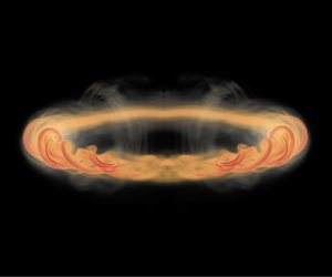
  $A = 4.3$ in figure 3. (Similar snapshots for all other parameter combinations are shown in supplementary material § 1 available at https://doi.org/10.1017/jfm.2024.367.) Similar to the straight tube case discussed in Ji & van Rees (Reference Ji and van Rees2022), the differential rotation rates along the curved vortex tube lead to the generation of left-handed and right-handed twist wave packets emanating from the core perturbation (figure 3a). The signs of these twist waves can be inferred from the helicity density field, with positive values (red) for the right-handed twist waves, and negative values (blue) for the left-handed twist waves. The twist wave packets propagate along the vortex axis, and their collision leads to the appearance of a ring-like bursting structure (figure 3b).These features (twist wave, initial ring-like bursting) are common to all parameter values considered (across both $R/p$ and $A$). For the $A4.R2$ case shown in figure 3, the initially ring-like bursting structure becomes non-axisymmetric and disintegrates into small-scale structures (figures 3c–e). Closer to the centreline, twist waves of opposite signs are generated inside the core, which propagate away from the bursting location (figures 3e,f). At the latest time shown (figure 3f), the axial flow associated with these twist regions has destabilized the vortex core, and the flow in the core region can be characterized by intertwined helical filamentous vortical structures. Further, at this time, strong opposite-signed helical ring-like structures appear in the helicity field at the periodic boundary of the computational domain, representing the reversal of the azimuthal vorticity during the second bursting event.

Figure 3. The 3-D volume rendering of vorticity magnitude  $|\boldsymbol {\omega }|$ and helicity density $h = \boldsymbol {u} \boldsymbol {\cdot } \boldsymbol {\omega }$ field for the case $R/p = 0.02$ and $A = 4.3$ at different times.
Analogous to Ji & van Rees (Reference Ji and van Rees2022), we define three phases of the flow evolution: the early-time twist wave propagation, the vortex bursting itself, and the late-time flow evolution. These phases are discussed below in more detail.
3.2. Early-time twist wave propagation
The core dynamics associated with the initial core size perturbation yields two opposite-signed twist waves that propagate away from the bump (Melander & Hussain Reference Melander and Hussain1994; Arendt et al. Reference Arendt, Fritts and Andreassen1997). When the centreline of the vortex tube is straight ( $R/p = 0$), the left- and right-handed twist waves both travel at the same speed, and the non-dimensional propagation speed of the twist waves, $c^* = c/(\varGamma _0/\sigma _0)$, was found to increase linearly with the core size ratio $A$ (Ji & van Rees Reference Ji and van Rees2022). For the helical vortices, even in the absence of core size perturbations ( $A=1$), the centreline geometry is associated with a self-induced velocity component $U_t$ tangent to the centreline, which leads to a net flow in the positive $z$ direction. When analysing the twist wave speeds due to the core perturbation, we thus expect a difference between the speed of the left-handed ( $c_L$) and right-handed ( $c_R$) twist waves in the lab frame, and that $c_L < c_R$.
To investigate this, the speed with which the left- and right-handed twist waves propagate along the centreline of the vortex tube is quantified as follows. First, the centreline of the vortex tube is described as the set of vorticity centroids on constant- $z$ slices (supplementary material § 2), which captures the vortical structure well during this early phase of the flow. Then the wave front is identified as the location where the tangential component of the vorticity vector has a local minimum value along the centreline, coinciding with the inner expansion of the vortex core (see supplementary material of Ji & van Rees Reference Ji and van Rees2022). By tracking this location over time, up until the start of the bursting, and performing a linear fit of the resulting data, an approximation to the twist wave speed is obtained as the slope of this linear fit. This wave speed is measured along the centreline curve, so that its magnitude can be compared to the tangential component of the self-induced velocity $U_t$. The computed values of the wave speed for the left- and right-handed twist waves are listed in supplementary material § 3. The results show that for the small radius-to-pitch ratios considered here, both left- and right-handed twist wave propagation speeds are at least two orders of magnitude larger than the self-induced axial flow speeds $U_t$ of an equivalent unperturbed helical vortex with the same centreline geometry. The average of these twist wave speeds is close to that of the straight vortex tube with the same core size ratio $A$, computed in Ji & van Rees (Reference Ji and van Rees2022), indicating a very weak dependency of the twist wave dynamics on $R/p$. Examining $c_L$ and $c_R$ independently confirms that there exists a small difference in speed between them, with $c_L < c_R$, as expected. The difference $c_R - c_L$ is of magnitude comparable to the self-induced axial velocity at the centreline for the corresponding unperturbed helix, which increases with $R/p$. Overall, this means the non-zero torsion of the centreline has a small but predictable effect on the twist wave propagation speeds, which becomes more pronounced with increasing $R/p$.
3.3. Bursting dynamics
Vortex bursting occurs when the two opposite-signed twist waves meet. For straight centrelines, the bursting structure resembles the head-on collision of opposite-signed vortex rings with significant swirl, though topologically, the vortex lines in the rings remain connected to each other and the tube (van Rees Reference van Rees2020). This bursting structure grows radially outwards before the growth is arrested due to a reversal in the azimuthal vorticity, which subsequently reverses the dynamic process as described in Ji & van Rees (Reference Ji and van Rees2022). A sketch of the typical vortex line geometry and the azimuthal vorticity in the bursting region on a rectilinear vortex tube is shown in figure 4(a), consistent with the findings of van Rees (Reference van Rees2020) and Ji & van Rees (Reference Ji and van Rees2022). The sketch shows a single pair of bursting rings with opposite-signed azimuthal vorticity. The vortex lines have an opposite handedness on the two sides of the bursting plane, and are of hairpin shape in the bursting region, bending in the swirling flow direction. For the case with core size ratio  $A = 4.3$ (figure 4b), multiple pairs of bursting rings appear consecutively, and vortex line geometries are more complex due to the radially varying azimuthal vorticity field.

Figure 4. Sketch of two selected vortex lines (in black) passing through the bursting region on a rectilinear vortex for the cases of (a) a single pair of bursting rings (low  $A \sim 3$) and (b) two pairs of bursting rings ( $A\sim 4$). The arrows on the lines indicate the direction of $\boldsymbol {\omega }$. The semi-transparent rings indicate the regions with significant azimuthal vorticity. Red shows positive azimuthal vorticity, and blue shows negative azimuthal vorticity.
Starting from this baseline scenario, in this subsection we discuss how the curvature/torsion of the helical vortex centreline affects this mechanism, starting with the cases where  $A=3$, and subsequently considering $A=4.3$.
3.3.1. Effect of helical centreline for moderate core size ratio  $A = 3$

Figure 5 shows the 3-D vorticity magnitude field in the bursting region for cases with core size ratio  $A = 3$ and (from top to bottom) $R/p = 0$, $R/p = 0.02$ and $R/p=0.04$. For each case, four temporal snapshots of the flow are shown from left to right. For the case with a straight centreline, bursting appears as an annular structure with high vorticity magnitude, exhibits axisymmetric radial growth from $t^* =45$ to $t^* = 65$, and remains stable during growth and subsequent decay. On the helical centrelines with $R/p \ge 0.02$, the bursting structure initially (at $t^*=45$) appears similar to the straight vortex tube, though slightly tilted due to the time-varying orientation of the centreline normal plane. At later times, the bursting structure on the helical vortex tubes loses its axisymmetry and becomes highly distorted, as seen in figure 5.

Figure 5. The 3-D volume rendering of the vorticity magnitude field at different times (increasing from left to right) during bursting for vortex tubes with  $A = 3$ and different $R/p$ values (increasing from top to bottom).
To investigate the onset of the loss of axisymmetry, we probe the structure of the vorticity field during bursting for case  $A3.R2$ in more detail. To facilitate the analysis, we first identify the centroid of the bursting structure. At a given snapshot of the simulation, this bursting centroid $\boldsymbol {x}_b$ is defined as the centroid of vorticity magnitude in a truncated rectangular domain $V_t$ containing the bursting region ( $0.8L_z< z/\sigma _0 <1.2L_z$), so that $\boldsymbol {x}_b = \int _{V_t} |\boldsymbol {\omega }|\,\boldsymbol {x} \,{\rm d}V/\int _{V_t} |\boldsymbol {\omega }|\,{\rm d}V$. After identifying the bursting structure centroid, we extract the local Frenet frame at that location on the corresponding unperturbed helical tube (case $A1.R2$), for which the centreline remains a helix over time. We use that Frenet frame of the undisturbed vortex to estimate the local tangent, normal, and binormal vectors of the bursting case $A3.R2$, which we refer to below as $\boldsymbol {T}$, $\boldsymbol {N}$ and $\boldsymbol {B}$, respectively (see figure 6a).

Figure 6. Evolution of the vorticity field during bursting for the case  $A3.R2$. (a,d) Volume rendering of the vorticity magnitude field at $t^* = 65$, annotated with the local Frenet frame and a sketch of the planes (a) normal to the $\boldsymbol {N}$ vector, and (d) normal to the $\boldsymbol {B}$ vector. (b,e) A 3-D schematic explaining how the rotation of the centreline tilts the azimuthal vorticity that constitutes the bursting ring pair. The colours show the vorticity component normal to the highlighted planes (in grey), which match with (a,d). (c,f) Three different time instances of the cross-section of the vorticity field (c) normal to the $\boldsymbol {N}$ plane and (f) normal to the $\boldsymbol {T}$ plane, matching with (a,b) and (d,e), respectively.
During bursting, the twist waves continuously transport azimuthal vorticity into the bursting region, forming a structure akin to a vortex ring pair that expands radially over time (Ji & van Rees Reference Ji and van Rees2022). Simultaneously, due to the self-induced translation and rotation of the centreline, the Frenet frame rotates primarily around the binormal ( $\boldsymbol {B}$) axis as time evolves. Abstractly, we can then imagine the bursting structure to be the superposition of opposite-signed, growing vortex ring pairs that emanate on either side of the bursting plane. Each vortex ring pair has an orientation that is determined by the centreline tangent vector at the time of the ring pair's formation. This process is sketched in figures 6(b) and 6(e), showing two ring pairs generated at subsequent time instances. Because the outer pair is generated at an earlier time than the inner pair, the outer pair has a larger diameter. Further, because the centreline tangent direction changes over time, the inner pair has a different orientation compared to the outer pair. Figure 6(b) also highlights the plane normal to the $\boldsymbol {N}$ direction, and the rings are coloured according to the azimuthal vorticity component in that plane. Figure 6(e) instead highlights the plane normal to the $\boldsymbol {B}$ direction, and the colouring here is changed accordingly. From these two sketches, we can observe that the rotation of the centreline affects the vorticity field differently between the $\boldsymbol {N}$-normal plane in figure 6(b) and the $\boldsymbol {T}$-normal plane in figure 6(e). In figure 6(b), the legs of the vortex rings intersecting the $\boldsymbol {N}$-normal plane are unaffected by the temporally changing orientation, so azimuthal vorticity is accumulated over time. In figure 6(e), however, we observe that as the ring pair changes orientation, opposite-signed azimuthal vorticity components lead to distortion and partial cancellation of the vorticity in the $\boldsymbol {B}$-normal plane.
The effects of these dynamics are shown in figures 6(c) and 6(f), which show actual slices of the simulated vorticity field normal to the  $\boldsymbol {N}$ plane (top) and normal to the $\boldsymbol {B}$ plane (bottom), coloured by the azimuthal vorticity component (the component normal to each plane). For the $\boldsymbol {N}$-normal plane (top), the vortex ring pair (represented as dipoles in this slice) is shown to grow roughly symmetrically about the bursting structure orientation, with both rings in the pair remaining approximately equally strong in this slice. On the other hand, in the $\boldsymbol {T}$-normal plane (bottom), the positive normal vorticity (in red) dominates but the negative normal vorticity (in blue) is weaker, consistent with the cancellation hypothesis arising from figure 6(e). Because of this difference in strength, the positive azimuthal vorticity entrains the weaker, negative vorticity in this plane, as shown in figure 6(f). Returning to bursting as a 3-D structure, this difference between the two planes explains how the centreline dynamics introduces a strong non-axisymmetry into the bursting structure. This is the onset of the non-axisymmetric evolution of the bursting structure that governs $A=3$ (figure 5) and leads to instabilities for $A=4.3$ discussed in the next subsubsection.
3.3.2. Effect of helical centreline for higher core size ratio $A = 4.3$

Figure 7 shows the 3-D vorticity magnitude field in the bursting region for cases with core size ratio  $A = 4.3$, where from top to bottom, $R/p = 0$, $R/p = 0.02$ and $R/p=0.04$, and for each case, four temporal snapshots of the flow are shown from left to right. For a vortex tube with straight centreline ( $R/p=0$), an increase in the core size ratio from $A=3$ to $A=4.3$ leads to the successive generation of multiple concentric bursting ring pairs (Ji & van Rees Reference Ji and van Rees2022). These successive ring pairs do not significantly affect the bursting dynamics compared with $A=3$, as the bursting structure remains axisymmetric and stable. When the centreline becomes increasingly helical as $R/p$ increases, however, the bursting structure becomes distorted due to the centreline dynamics, as discussed in the previous subsubsection for $A=3$. Consequently, the successively generated bursting ring pairs are no longer concentric at $t^* = 45$ (figure 7); instead, they can be thought of as being aligned on different planes. Further, due to cancellation, the ring pairs can no longer be identified as separate vortical structures, as in the case of $R/p=0$. A figure equivalent to figure 6, but for case $A=4.3$, is shown in supplementary material § 4. This supports the claim that the bursting dynamics on helical vortices at $A=4.3$ is similar to that for $A=3$, though with stronger secondary structures due to the increased strength of the azimuthal vorticity field. At times beyond $t^*=45$, we observe breakup of the bursting structure into small-scale structures by $t^* = 65$ (figure 7), even at the smallest radius-to-pitch ratio $R/p=0.02$. This can be contrasted with the head-on collision of two opposite-signed vortex rings, where experiments and numerical simulations revealed that an iterative cascade instability leads to the breakdown of the vortex ring core into a turbulent cloud (McKeown et al. Reference McKeown, Ostilla-Mónico, Pumir, Brenner and Rubinstein2018). In our case, the breakdown of the bursting structure is driven by the swirling flow and deformation due to the centreline dynamics, as discussed in § 3.3.1. At even later times, the small-scale structures develop further as the bursting structure breaks down (see the flow visualizations at $t^*=100$ in figure 7); their effect on the long-time flow evolution will be discussed in the next subsection.

Figure 7. The 3-D volume rendering of the vorticity magnitude field at different times (increasing from left to right) during bursting for vortex tubes with  $A = 4.3$ and different $R/p$ values (increasing from top to bottom).
3.4. Long-time flow evolution
Despite the breakdown of the bursting structure, the bursting process on helical vortex tubes still leads to twist wave reversals and further bursting events within the periodic simulation domain, as in the straight tube cases. After the first bursting event, however, long-wave instabilities set in, manifesting themselves as helical strands of strong vorticity magnitude winding around the remnant of the centreline, as shown in figure 3(f). Note that these instabilities are also observed for some of the straight vortex tube simulations, but only when  $A \ge 4.3$, and well after the second bursting event ( $t^*>160$) (Ji & van Rees Reference Ji and van Rees2022). Helical vortex tubes are more susceptible to these instabilities: for $A = 3$, they set in at time $t^* \approx 120\unicode{x2013}145$, and for $A = 4.3$, at time $t^* \approx 120\unicode{x2013}130$. To quantify how bursting and the subsequent instabilities on helical vortex tubes influence the flow diagnostics, we examine enstrophy and energy evolutions in more detail in the following subsubsections.
3.4.1. Enstrophy density integrated over $x\unicode{x2013}y$ planes

To get an overview of the flow evolution, we compute the time evolution of enstrophy density integrated over  $x\unicode{x2013}y$ planes, $\varOmega (z,t) = \iint \boldsymbol {\omega } \boldsymbol {\cdot } \boldsymbol {\omega } \,{\rm d}\kern0.06em x\,{\rm d}y$, which is shown in figure 8 for two helical turns of case $A3.R4$. The twist wave propagation is associated with the streaks of light colour, since there is a low value of $\varOmega$ at the twist wave front. The bursting events are associated with regions of high values of $\varOmega$ and are outlined with black ellipses. There is a clear shift in bursting location between the first and third bursting events (denoted by the green dashed line), associated with the axial flow induced by the helical centreline discussed in § 3.2. Further, the enstrophy density highlights the core instabilities after the second bursting event as irregular streaks of high enstrophy that linger around the bursting region even after the twist wave reverses. The presence of these instabilities inhibits further strong bursting events: the enstrophy density highlights a weak tertiary bursting around $t^*=240$ followed by an uneventful flow evolution, characterized by a largely uniform enstrophy density distribution.

Figure 8. (a) Colour plot of enstrophy density integrated over  $x\unicode{x2013}y$ planes, $\varOmega (z,t) = \iint \boldsymbol {\omega } \boldsymbol {\cdot } \boldsymbol {\omega } \,{\rm d}\kern0.06em x\,{\rm d}y$, for the case $R/p = 0.04$, $A = 3$, for two helical turns. The horizontal axis represents the $z$ extent of the vortex tube, and the vertical axis represents time. (b) An appropriately scaled schematic of the helical tube projected onto the $r\unicode{x2013}z$ plane.
3.4.2. Global enstrophy and energy
As in the straight tube case, bursting events on helical vortex tubes are associated with a significant increase in the global enstrophy  $\varepsilon = \int \boldsymbol {\omega } \boldsymbol {\cdot } \boldsymbol {\omega } \,{\rm d}V$ (figure 9a) and thus an accelerated energy dissipation (figure 9b) compared to unperturbed tubes. For the small $R/p$ values considered, the time evolution of global enstrophy and energy follows trends very similar to those for the corresponding straight tube case with the same core size ratio $A$.
$A$.

Figure 9. Time evolution of (a) global enstrophy  $\varepsilon =\int \boldsymbol {\omega } \boldsymbol {\cdot } \boldsymbol {\omega } \,{\rm d}V$, (b) total energy $E = \frac {1}{2} \int \boldsymbol {\psi } \boldsymbol {\cdot } \boldsymbol {\omega } \,{\rm d}V$, (c) $\gamma (t^*) = E_{{small\text -scale}} / E$, for straight and helical vortex tubes with various values of initial core-size ratio $A$ and radius-to-pitch ratio $R/p$.
Bursting leads to the generation of small-scale vortical structures, especially when instabilities disrupt the core of the vortex tube. To quantify the amount of energy contained in the small scales, we consider the energy contained for wavenumber  $k \leq 2{\rm \pi} /\sigma _0$, i.e. $E_{{small\text -scale}} = \int _{2 {\rm \pi}/\sigma _0}^{\infty }E(k)\,{\rm d}k$, as a fraction of the global energy $E$. We denote this quantity $\gamma (t^*) = E_{{small\text -scale}} / E$, and plot its evolution in figure 9(c) for the cases $A3.R0$, $A3.R4$, $A4.R0$ and $A4.R4$, as well as the reference cases $A1.R0$ and $A1.R4$ that do not undergo bursting. For the reference cases ( $A=1$), the percentage of energy contained in these scales smaller than the mean core size is almost zero during the long-time evolution of the flow. In contrast, for the cases $A>1$, the fraction of small-scale energy increases significantly until $t^* \approx 170$, which is the time during which the dominant bursting events occur. For $t^*\gtrsim 170$, the small-scale energy fraction decays as the main bursting events are over, and viscous dissipation becomes dominant in the flow evolution. The time evolution of $\gamma$ for straight and helical vortex tubes with identical values of $A$ are comparable in their trends and peak values. Together with the plots in figures 9(a) and 9(b), this indicates that the global enstrophy and energy evolution, as well as the distribution of the total energy across the dominant length scales, is largely determined by $A$ rather than the specific shape of the centreline.
3.4.3. Global helicity
The global helicity  $H = \int \boldsymbol {u} \boldsymbol {\cdot } \boldsymbol {\omega } \,{\rm d}V$ is proportional to the degree of linking of the vortex lines (Moffat & Ricca Reference Moffat and Ricca1992). For a single thin vortex bundle, helicity is related to the geometry of the centreline of the vortex tube and the surrounding vortex lines through the expression $H = \varGamma _0^2 (Wr + Tw)$, where $\varGamma _0$ is the circulation of the vortex tube, $Wr$ is the writhe of the centreline of the tube and $Tw$ is a measure of the total twist of the vortex lines (Moffat & Ricca Reference Moffat and Ricca1992; Scheeler et al. Reference Scheeler, van Rees, Kedia, Kleckner and Irvine2017). In the context of this work, the vortex lines are initially untwisted in all cases. Consequently the initial global helicity can be expressed analytically as $H(t^*=0) = \varGamma _0^2\,Wr(t^*=0)$, where the writhe of the helical centreline is $Wr(t^*=0) = 1 - \cos (\phi _{h})$, with $\phi _h = \arctan (2{\rm \pi} R/p)$ (White & Bauer Reference White and Bauer1986). The initial helicity thus is zero for straight vortex tubes ( $R/p=0$), and increases with $R/p>0$; notably, it does not depend on the core size perturbation parameter $A$.
$A$.
The time evolution of the helicity for three different  $A$ values, at both $R/p=0$ and $R/p=0.04$, is shown in figure 10(a). As expected, for straight vortex tubes ( $R/p=0$), the global helicity remains identically zero due to symmetry for all values of $A$. For the unperturbed ( $A=1$) helical vortex tube with $R/p=0.04$, the helicity remains constant, consistent with the notion that helicity is preserved for an untwisted vortex bundle with writhe (Scheeler et al. Reference Scheeler, van Rees, Kedia, Kleckner and Irvine2017). For helical vortex tubes with $R/p=0.04$ and $A>1$, the helicity initially remains constant across the different perturbation amplitudes, but then deviates from these values starting around the initial bursting event.

Figure 10. (a) The time evolution of the global helicity  $H= \int \boldsymbol {\omega } \boldsymbol {\cdot } \boldsymbol {u} \,{\rm d}V$. (b) The time evolution of the mean of the positive and negative global helicity $\frac {1}{2}(H^+ + H^-)$.
To analyse how bursting affects the helicity evolution, we define a simple sign-based composition of the helicity as  $H(t) = H^+(t) - H^-(t)$, where $H^{\pm } = \int|h^{\pm }| \,{\rm d}V$, and
 \begin{equation} h^+= \begin{cases} h & \text{if } h \geq 0,\\ 0 & \text{otherwise}, \end{cases} \end{equation}
and  $h^- = h^+-h$. This approach is then able to capture the positive and negative twist waves in the domain independently, and was also used in Shen et al. (Reference Shen, Yao, Hussain and Yang2022, Reference Shen, Yao, Hussain and Yang2023). Further, we can define the average between the components of different signs as $\bar {H} = \frac {1}{2}(H^++H^-)$, which is visualized in figure 10(b) for $R/p=0$ and $R/p=0.04$ at three different values of $A$. For unperturbed vortex tubes ( $A=1$), there are no twist waves, and $\bar {H} = 0$ for $R/p=0$ (solid green line). For the helical tube $R/p=0.04$ with $A=1$ (dash-dotted green line), $\bar {H}$ is very small as it captures only the helicity components associated with the persisting writhe of the tube. For $A>1$, the values $\bar {H}$ are two orders of magnitude larger than $H$ and oscillate slowly, reaching peaks around each bursting instance (blue and orange dash-dotted lines in figure 10b). In fact, compared to the other global metrics used in this work, the evolution of $\bar {H}$ yields the clearest identification of the twist wave dynamics and bursting events across all parameters studied here. For each $A$,
$A$,  $\bar {H}$ is slightly higher for the helical tubes compared with the straight tube due to the persisting writhe of the centreline. Notably, the evolution of $\bar {H}$ differs significantly between $A=3$ and $A=4.3$, but does not vary strongly with $R/p$. As for the other global metrics discussed above, this implies that the centreline geometry does not have a strong effect on the global flow evolution of a vortex with a given initial core size ratio.
Returning to the global helicity  $H = H^+ - H^-$ in figure 10(a), we observe that the variations of $H$ for $R/p=0.04$ after bursting, i.e. the differences between $H^+$ and $H^-$, are negligible compared to the magnitudes of $H^+$ and $H^-$ individually. Small physical or numerical perturbations in the flow evolution during bursting on helical vortex tubes are easily picked up in the total helicity evolution plotted in figure 10(a), yet are insignificant compared to the dominant and physically relevant variations in $H^+$ and $H^-$.
3.5. Bursting on helical vortices with larger $R/p$ ratios

Though the focus in this work is on the bursting dynamics on elongated vortices with small perturbations from rectilinearity, the case of  $R/p \sim O(1)$ has practical relevance in many engineering applications as well. A full investigation is beyond the scope of this work, but we can use the results presented above to hypothesize about this scenario.
In general, helical vortices with large  $R/p$ ratios are unstable and susceptible to long- and short-wave instabilities even in the absence of any core-size perturbations or twist waves (Widnall Reference Widnall1972; Leweke et al. Reference Leweke, Quaranta, Bolnot, Blanco-Rodríguez and Le Dizés2014). However, based on the assessment in supplementary material § 3, the initial twist wave generation should not differ much from the cases discussed in our paper, except that the strong axial flows associated with the helical vortices with large $R/p$ ratios will lead to large differences in the left- and right-propagating twist wave speeds. The subsequent evolution of the flow, however, is expected to change drastically compared to the results shown above. The stability characteristics of helical vortex loops depend strongly on the axial flow and torsion (Hattori & Fukumoto Reference Hattori and Fukumoto2012, Reference Hattori and Fukumoto2013), and the growth rates depend on the specific parameters of the vortex. Preliminary numerical results (not shown here), demonstrate indeed that for $R/p = 0.5$, the twist waves rapidly destabilize into helical strands similar to those observed in the results presented above (e.g. figure 3f). These strands interact between adjacent loops and grow into larger-scale disruptions to the evolution of the flow. If the time scale of the destabilization of the twist waves is less than the time that it would take the twist waves to meet at the bursting location, then bursting as a distinct mechanism could well be suppressed in these cases. However, for other vortices, the twist waves might remain stable for longer, in which case the flow would evolve similarly to the small $R/p$ cases discussed above.
4. Results on vortex rings with initial core size variations
For vortex rings with an initial core size perturbation at  $\theta =0$, the generated twist waves travel along the circumference leading to bursting at the opposite end $\theta ={\rm \pi}$. The bursting is visible at $t^*=120$ for case $A3$, and at $t^*=80$ for case $A4$, as shown in the visualizations of the vorticity magnitude field in figure 11. An additional simulation for a ring with smaller core-to-radius ratio is shown in supplementary material § 7, with results very similar to those shown in figure 11.

Figure 11. Volume rendering of the vorticity magnitude  $|\boldsymbol {\omega }|$ of a bursting ring at different times (left to right) for (a) $A=3$ and (b) $A=4.3$.
We provide a schematic for the vortex line and vortex surface structure of a vortex ring undergoing bursting in figure 12. The vortex line structure is very similar to that depicted in figure 10 of Lim (Reference Lim1989). That work discusses an experimental study into the evolution of a vortex ring of Reynolds number 600 interacting with an inclined wall. The secondary vortex produced by the wall interaction causes the vortex lines in the ring to coil. These vortex lines are denoted as ‘bi-helical vortex lines’ in Lim (Reference Lim1989), due to their opposite-handedness on either side of the symmetry plane, similar to the vortex lines in our configuration. In the experimental results, these coiled vortex lines are continuously displaced and eventually compressed into a narrow region where a local increase in the core radius occurs, reminiscent of the bursting event in our results. This sequence of events is similar to the twist wave generation, propagation and bursting that we observe in the current simulations, demonstrating that strain fields induced by secondary vortices can lead to the colliding of opposite-signed twist waves and vortical structures similar to bursting as discussed here.

Figure 12. Schematic of the vortex surface and vortex line structure for a vortex ring with core-size variation at each phase of evolution. The solid black line denotes a vortex line lying on a vortex surface (the semi-transparent yellow surface), and the grey dashed line denotes the centreline of the ring. (a) The initial unperturbed state. (b) The twist wave propagation stage. (c) The bursting event.
These early-time results are further consistent with those reported recently in Shen et al. (Reference Shen, Yao, Hussain and Yang2023), where the evolution of vortex rings with initial differential twist distributions at a lower Reynolds number  $Re_{\varGamma }=2000$ were simulated and analysed in detail. In this work, we thus do not further analyse the early phase of the flow evolution in detail, and instead focus on the bursting dynamics and late-time evolution. After the onset of bursting, we find that the bursting structure immediately becomes unstable, and a reversal of the twist waves is accompanied by helical filamentous strands of high vorticity magnitude as in the helical vortices discussed above. These vortical structures resemble those of earlier numerical studies on vortex rings with swirl by Cheng, Lou & Lim (Reference Cheng, Lou and Lim2010). In that work, it is argued that the centrifugal force associated with swirl drives the flow radially outwards. In Cheng et al. (Reference Cheng, Lou and Lim2010), this leads to a secondary vortex ring that, for sufficiently strong swirl, rolls up around the primary one to create helical filamentous strands winding around the core. We believe that this generation mechanism is different from our results in figure 11, where the interaction of two opposite-signed swirling flows at the bursting plane triggers the destabilization of the vortex core. Nevertheless, the results of Cheng et al. (Reference Cheng, Lou and Lim2010) provide insights into the potential longer-term dynamics of this flow, such as the possible generation of ringlet vortices of opposite polarizations from the swirling regions of the ring.
Below, we discuss some of the features of the flow evolution, focusing in particular on features specific to the circular centreline as well as differences from the helical tubes above.
4.1. Centreline geometry
We find that the twist wave propagation and subsequent vortex bursting affects the global shape of the vortex ring. To demonstrate this, we define a centreline  $\boldsymbol {x}_c(\theta,t)$ of the vortex ring as the set of centroids of $\omega _{\theta }$ on constant- $\theta$ slices, i.e.
 \begin{equation} \boldsymbol{x}_c(\theta,t) = \frac{\displaystyle\int \omega_{\theta} \boldsymbol{x} \,{\rm d}S}{\displaystyle\int \omega_{\theta} \,{\rm d}S}. \end{equation}
A plot of the evolution of the vertical coordinate of the centreline,  $z_c(\theta,t)$, is shown in supplementary material § 5, figure 4, illustrating that the ring gets distorted during the flow evolution. Specifically, the side where the initial core size perturbation is located ( $\theta = 0$), and the initial vorticity magnitude is lower, travels more slowly upwards than the opposite side ( $\theta ={\rm \pi}$), where the initial vorticity magnitude is higher. Consequently, the rings are non-planar when bursting starts (at approximately $t^*=120$ for $A=3$, and $t^*=80$ for $A=4$), though for the large radius-to-core size ratios chosen here, this does not yield significant additional strains on the bursting region. For smaller radius rings, this effect could become more pronounced and affect the evolution of vortex bursting.
4.2. Bursting
The  $\omega _z$ field on cross-sectional slices at $z = \bar {z}_c(t)$ at different times is shown in figure 13. The vorticity dynamics at the onset of bursting is similar to the cases discussed above, and thus matches across all centrelines considered here. To describe the further flow evolution, we introduce some additional notation: referring to figure 13(a), we denote the toroidal coordinate by $\theta$ so that the bursting plane is $\theta ={\rm \pi}$, and the poloidal coordinate by $\zeta$. Returning to the flow, it can be seen that the bursting structure grows non-axisymmetrically within the bursting plane for both cases $A3$ and $A4$. Specifically, the bursting ring pair grows radially outwards at $\zeta =0$, i.e. on the outer side of the main vortex ring, but the growth on the inner side $\zeta = {\rm \pi}$ stagnates. Within the cross-sectional plane (figures 13b)–e), this is reflected by the outer dipoles growing and stretch due to the curvature of the vortex ring, whereas the inner dipole persists as a coherent vortex pair during this time. This non-constant growth is seen in figure 13(e) as an apparent outward shift of the vorticity centreline in the bursting plane. In three dimensions, this presents a picture of a bursting ring pair that is strongly non-axisymmetric along the $\zeta$ (poloidal) direction, i.e. between the inside and the outside of the main vortex ring. Though the nature of this asymmetry of the bursting ring pair is different from that of the helical tube discussed above, the effect on the global flow evolution is similar: the bursting structure becomes unstable and disintegrates into helical, filamentous structures of strong vorticity magnitude amplified by the secondary twist waves.

Figure 13. (a) A perspective view of the vorticity magnitude field for case  $A3$ at a time instant during bursting, and sketches of the cross-sectional plane ( $z = \bar {z}_c$) and the bursting plane. Zoomed views of $\omega _z$ on the cross-sectional plane around the bursting location at different times for (b–e) case $A3$, and (f–i) case $A4$. The full views of the slices are shown in supplementary material § 6).
For these bursting ring cases, the helical filamentous structures are reminiscent of those emanating from regions of vortex reconnection, where differential twist is also responsible for axial flows moving away from the strongly perturbed region of a reconnected vortex ring (Melander & Hussain Reference Melander and Hussain1994; van Rees et al. Reference van Rees, Hussain and Koumoutsakos2012; Yao & Hussain Reference Yao and Hussain2021). This poses an interesting proposition on the potential of vortex bursting occurring when multiple vortex reconnection events happen on the same vortical structure, each associated with the generation of twist waves. As these twist waves travel away from their respective reconnection regions, they could meet elsewhere on the tube and cause a vortex bursting event. In particular, this could occur on knotted vortex loops and vortex links, which typically evolve towards simpler topologies through successive events of reconnection and merging (Kleckner & Irvine Reference Kleckner and Irvine2013; Zhao & Scalo Reference Zhao and Scalo2021). The detailed helicity dynamics of these vortices has been analysed carefully by Zhao & Scalo (Reference Zhao and Scalo2021), Shen et al. (Reference Shen, Yao, Hussain and Yang2022) and Yao et al. (Reference Yao, Shen, Yang and Hussain2022), and demonstrates the generation of axial flow from the reconnection regions. However, since these studies focus on the reconnection and unlinking process, they do not follow the flow for sufficiently long to track the evolution of the coiled vortex lines. A future research effort would be needed to demonstrate whether or not bursting occurs when two opposite-signed twist waves meet on reconnected vortex tubes.
4.3. Flow diagnostics
Similar to the helical vortex tube cases, a global view of the flow evolution can be obtained by considering the enstrophy integrated over the radial planes each with constant  $\theta$, i.e. $\varOmega (\theta,t) = \iint \boldsymbol {\omega } \boldsymbol {\cdot } \boldsymbol {\omega } \,{\rm d}z\,{\rm d}r$, as shown in figures 14(a) and 14(b) for cases $A3$ and $A4$, respectively. As there is no torsion in the vortex ring centrelines, the symmetry between the left- and right-handed twist waves remains preserved. For case $A4$, instabilities on the second twist waves lead to regions of high enstrophy density that remain on either side of the bursting plane until $t^*\approx 250$. The evolution of total enstrophy, shown in figure 14(c), again demonstrates that bursting leads to an increase in enstrophy, which becomes more pronounced as $A$, and hence the twist magnitude, increases. This is associated with an accelerated energy dissipation, similar to the straight and helical vortex tube cases shown in figure 9.

Figure 14. Colour plots of the enstrophy integrated over radial planes,  $\varOmega (\theta,t) = \iint \boldsymbol {\omega } \boldsymbol {\cdot } \boldsymbol {\omega } \,{\rm d}z\,{\rm d}r$ for (a) $A=3$ and (b) $A=4.3$. The horizontal axis represents the toroidal angle $\theta$, and the vertical axis represents time. (c) The global enstrophy $\varepsilon = \int \boldsymbol {\omega } \boldsymbol {\cdot } \boldsymbol {\omega } \,{\rm d}V$ for an unperturbed vortex ring (green) as well as bursting rings with $A=3$ (blue) and $A=4.3$ (orange).
5. Conclusions
In this work, we numerically studied bursting on helical vortex tubes with small radius-to-pitch ratios  $0 \leq R/p \leq 0.0625$ and initial core size ratio $1< A\leq 4.3$, as well as vortex rings with a large curvature ratio $R/\sigma _0 = 10$ and initial core size ratios $A = 3$ and $4.3$. A primary result is that vortex bursting is a robust phenomenon that appears across the centreline geometries considered, including in the presence of curvature and torsion. The qualitative effects of bursting remain similar, independent of the precise nature of the centreline: notably, bursting is always associated with an increase in enstrophy density in the bursting region, thus increasing overall enstrophy and accelerating energy dissipation. These trends become more pronounced when the twist wave strength, as determined by the initial core size ratio $A$, increases, largely independent of the precise torsion and/or curvature of the centreline.
A more in-depth analysis of the bursting dynamics and flow evolution does demonstrate several key differences between the curved and straight vortex tubes. Starting with the twist wave propagation speed, the self-induced axial flow of helical vortex tubes leads to a different speed between the left- and right-propagating twist waves. This results in a small shift in the location of the bursting events in the lab frame. For vortex rings, the self-induced motion is predominantly perpendicular to the direction of the twist wave propagation, which means that the left- and right-propagation twist waves still have the same speed when viewed in the frame of the vortex ring.
During bursting, a major consequence of a non-rectilinear centreline is the intrinsic distortion in the bursting ring pair. For the helical vortex tube, the distortion can be related to the combined process of a radially growing bursting ring pair and a rotating centreline, which leads to selective cancellation of vorticity along part of the bursting ring pair. For the vortex ring, on the other hand, the curvature causes a difference in radial growth rate between the inner and outer parts of the bursting ring pair, effectively stagnating the inner part of the bursting structure ring as the outer part grows radially and stretches circumferentially. In both cases, the configuration of tilted and/or non-axisymmetric ring pairs is unstable at the Reynolds number considered, resulting in an instability that breaks up the bursting ring pair into small-scale structures. These structures are stretched and wound around the centreline by the reversing twist waves, leading to filamentous helical strands of strong vorticity magnitude that emanate from the bursting region, similar to those observed after vortex reconnection (van Rees et al. Reference van Rees, Hussain and Koumoutsakos2012).
Finally, bursting does affect the global helicity on a helical vortex tube, as the global helicity of the helical vortex tube shows a small but finite variation from its initial value, related to a symmetry-breaking of the left- and right-propagating twist waves. However, our analysis shows that the variation in the helicity contained in the left- or right-propagation twist waves is orders of magnitude larger than their sum, and can be used to identify the twist wave dynamics and bursting events more precisely than by other global metrics.
Overall, our results show that bursting is robust to small centreline variations. Though the detailed evolution of the bursting structure and its coherence is sensitive to the curvature and torsion of the centreline geometry of the vortex tube, the global metrics of the flow remain largely dominated by the core size perturbation, independent of the centreline parameters. Given recent work by Shen et al. (Reference Shen, Yao, Hussain and Yang2023) showing that bursting can also be obtained with initial differential twist configurations, and observations on aircraft trailing wakes (Spalart Reference Spalart1998), we expect bursting events to be prevalent in many practical vortical flows, including reconnecting flows and possibly turbulent flows. Future work in this direction could be focused on characterizing the different ways in which such perturbations in core size or twist distribution can arise in practical flows, for instance through ambient strain fields (Pradeep & Hussain Reference Pradeep and Hussain2001; Kleusberg, Benard & Henningson Reference Kleusberg, Benard and Henningson2019), wing dynamics (Birch & Lee Reference Birch and Lee2005) or multiphase phenomena like cavitation (Ye, Wang & Shao Reference Ye, Wang and Shao2023).
Supplementary material and movies
Supplementary material and movies are available at https://doi.org/10.1017/jfm.2024.367.
Acknowledgements
This work used Bridges-2 at PSC through allocation PHY220086 from the Advanced Cyberinfrastructure Coordination Ecosystem: Services & Support (ACCESS) program (Boerner et al. Reference Boerner, Deems, Furlani, Knuth and Towns2023), which is supported by National Science Foundation grant nos 2138259, 2138286, 2138307, 2137603 and 2138296. In addition, this research used resources of the National Energy Research Scientific Computing Center (NERSC), a US Department of Energy Office of Science User Facility located at Lawrence Berkeley National Laboratory, operated under contract no. DE-AC02-05CH11231 using NERSC award ASCR-ERCAP002339. The authors further would like to thank James Gabbard for helping to formulate the transformations of the initial vorticity fields used in this work.
Funding
This research was supported by the US Army Research Office under award no. W911NF-211-0332.
Declaration of interests
The authors report no conflict of interest.


