


1. Introduction
In the study of magnetically confined fusion plasmas, energetic particle physics is a very important subject (Heidbrink Reference Heidbrink2008; Gorelenkov, Pinches & Toi Reference Gorelenkov, Pinches and Toi2014; Chen & Zonca Reference Chen and Zonca2016). Energetic particles come from auxiliary heatings such as neutral beam injection (NBI) or ion cyclotron resonance heating. Energetic particles are also produced from fusion reactions (i.e. alpha particles) in burning plasmas. Energetic particles can excite various instabilities such as Alfvén eigenmodes, fishbone modes (McGuire et al. Reference McGuire, Goldston, Bell, Bitter, Bol, Brau, Buchenauer, Crowley, Davis and Dylla1983; Chen, White & Rosenbluth Reference Chen, White and Rosenbluth1984; Coppi & Porcelli Reference Coppi and Porcelli1986; Betti & Freidberg Reference Betti and Freidberg1993; Wang Reference Wang2001; Yu et al. Reference Yu, Wang, Fu and Yu2019) and energetic particle modes (EPM) (Chen Reference Chen1994). These instabilities can lead to redistribution and losses of energetic particles. As a consequence, these instabilities may degrade energetic particle heating and even damage the first wall of a fusion reactor. Therefore, it is important to investigate the physics of the energetic particle-driven instabilities in tokamak plasmas.
In this work we focus on the energetic counter-passing particle-driven $n=1$ mode in tokamak plasmas. Here, $n$
 is the toroidal mode number. The prefix counter- denotes the direction of beam ion injection opposite to that of the plasma current. The prefix co- in context means that the direction of beam ion injection is the same as that of the plasma current. The case of the energetic co-passing particle-driven $n=1$
 mode has been investigated in our recent simulation study (Yang et al. Reference Yang, Fu, Shen and Ye2022). It is well known that energetic trapped particles can excite the $m/n=1/1$
 fishbone instabilities in a tokamak plasma with a monotonic safety factor $q$
 profile and the central $q$
 value less than unity (McGuire et al. Reference McGuire, Goldston, Bell, Bitter, Bol, Brau, Buchenauer, Crowley, Davis and Dylla1983; Chen et al. Reference Chen, White and Rosenbluth1984; Coppi & Porcelli Reference Coppi and Porcelli1986). Here, $m$
 is the poloidal mode number. The fishbone can be intrinsically an EPM with a mode frequency comparable to the processional drift frequency $\omega _{d,h}$
 of energetic trapped particles (Chen et al. Reference Chen, White and Rosenbluth1984). The fishbone can be excited when the energetic particle density exceeds a threshold. On the other hand, there is also another type of fishbone whose mode frequency is comparable to the diamagnetic drift frequency $\omega _{*,i}$
 of thermal ions. This fishbone instability, the so-called $\omega _{*,i}$
 branch, can also be resonantly destabilized by energetic trapped particles (Coppi & Porcelli Reference Coppi and Porcelli1986). Further work had shown that energetic passing particles can also excite fishbone instabilities (Betti & Freidberg Reference Betti and Freidberg1993; Wang Reference Wang2001). Betti et al. found that the low-frequency $\omega _{*,i}$
 fishbone can be destabilized by passing energetic particles when the effects of finite orbit width of the energetic particles is taken into account (Betti & Freidberg Reference Betti and Freidberg1993). The corresponding wave particle resonance is $\omega =k_{\parallel }v_\parallel$
 with $k_\parallel \sim (n-m/q)/R$
 being the parallel wavenumber with $(n,m)=(1,1)$
 and here R is the major radius. More recently, Yu et al. showed analytically that an EPM branch of the low-frequency fishbone can also be destabilized by energetic passing particles with mode frequency determined by the wave particle resonance $\omega =k_\parallel {v_\parallel }$
 when $\omega _{*,i}$
 is neglected (Yu et al. Reference Yu, Wang, Fu and Yu2019). The main conclusions of Yu's work have been confirmed qualitatively by our recent simulation study where the numerical results show that energetic co-passing particles can excite a low-frequency fishbone instability with mode frequency similar to the analytic result (Yang et al. Reference Yang, Fu, Shen and Ye2022). Finally, it was shown earlier that energetic co-passing particles can excite an $n=1$
 high-frequency fishbone of EPM type at a much higher mode frequency (Wang Reference Wang2001).
In this work, we extend our recent simulation study (Yang et al. Reference Yang, Fu, Shen and Ye2022) of the energetic co-passing particle-driven $n=1$ mode to the case of the energetic counter-passing particle-driven $n=1$
 mode in tokamak plasmas. The simulations have been carried out using the global kinetic-MHD (Magnetohydrodynamics) hybrid simulation code M3D-K (Fu et al. Reference Fu, Park, Strauss, Breslau, Chen, Jardin and Sugiyama2006). We consider tokamak parameters similar to those of the HL-2A experiments excepting the direction of neutral beam injection. The $q$
 profile is monotonically increasing with radius with its central value $q_0<1$
 . A systematic linear simulation study of key parameter dependences has been carried out. Parameter values of safety factor $q_0$
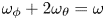
 , beam ion beta, beam ion injection energy and thermal plasma beta are scanned. Our linear simulation results show that the beam ion-driven modes are either EPMs or global Alfvén eigenmodes (GAEs) (Appert et al. Reference Appert, Gruber, Troyuon and Vaclavik1982; Mahajan, Ross & Chen Reference Mahajan, Ross and Chen1983). The mode frequencies are much higher than those of the low-frequency fishbone (Betti & Freidberg Reference Betti and Freidberg1993; Yu et al. Reference Yu, Wang, Fu and Yu2019). The main wave particle resonance driving the instability is identified as $\omega _\phi +2\omega _\theta =\omega$
 , where $\omega _\theta$
 is the poloidal transit frequency and $\omega _\phi$
 is the toroidal transit frequency of energetic particles. The nonlinear simulation results show initial mode saturation, a long quasi-steady saturation phase with upward frequency chirping, and finally a second growth phase with frequency jumping down to a lower value. Details of the results will be shown in § 3 and § 4.
This article is organized as follows: § 2 gives a brief introduction to the M3D-K code and parameters and profiles used in our simulation study. In § 3, linear simulation results of the energetic counter-passing particle-driven $n=1$ mode are presented. Section 4 gives the corresponding nonlinear simulation results of the $n=1$
 mode. Finally, a summary of this work is given in § 5.
2. Simulation model and parameter set-up
In this work, we use the global kinetic-MHD hybrid code M3D-K (Fu et al. Reference Fu, Park, Strauss, Breslau, Chen, Jardin and Sugiyama2006), in which a particle/MHD hybrid model is used to describe the interaction of energetic particles and MHD modes. In this model, the thermal plasma is treated as a single fluid while the energetic particles are described by the drift-kinetic equation. The drift-kinetic equation is solved by the particle-in-cell method (Fu et al. Reference Fu, Park, Strauss, Breslau, Chen, Jardin and Sugiyama2006). The M3D-K code has been successfully applied to study energetic particle-driven instabilities such as fishbone and energetic particle effects on MHD modes (Fu et al. Reference Fu, Park, Strauss, Breslau, Chen, Jardin and Sugiyama2006; Lang, Fu & Chen Reference Lang, Fu and Chen2010; Cai & Fu Reference Cai and Fu2012; Wang et al. Reference Wang, Fu, Breslau and Liu2013; Liu et al. Reference Liu, Fu, Crocker, Podestà, Breslau, Fredrickson and Kubota2015; Shen et al. Reference Shen, Fu, Tobias, Van Zeeland, Wang and Sheng2015, Reference Shen, Wang, Fu, Xu, Li and Liu2017; Zhu, Wang & Wang Reference Zhu, Wang and Wang2020).
In our simulations, parameters and profiles similar to those of HL-2A tokamak plasmas are used excepting the direction of neutral beam injection. In this work we consider counter-injection beam ions. The main parameters include the major radius $R_0=1.6\,{\rm m}$ , minor radius $a=0.4\,{\rm m}$
 , magnetic field $B_0=1.34\,{\rm T}$
 , central electron density $n_{e0}=1.3\times {10^{19}}\,{\rm m}^{-3}$
 , Alfvén speed $v_{A}=B_0/\sqrt {\mu _0\rho _0}=5.56\times {10^6}\,{\rm ms}^{-1}$
 , Alfvén time $\tau _{A}=R_0/v_{A}=2.88\times {10^{-7}}\,{\rm s}$
 and Alfvén frequency $\omega _{A}=1/\tau _{A}=3.7\times {10^{6}}\,{\rm s}^{-1}$
 . Both the thermal ion species and energetic ion species are deuterium ions. The thermal plasma and energetic particle beta profile are, respectively, $\beta _{{\rm thermal}}=\beta _{{\rm thermal}0}(1-\bar {\psi })^2$
 and $\beta _{{\rm hot}}=\beta _{{\rm hot}0}\exp (-\bar {\psi }/0.11)$
 , where $\bar {\psi }=(\psi -\psi _{\min })/(\psi _{\max }-\psi _{\min })$
 is the normalized poloidal magnetic flux varying from $\bar {\psi }=0$
 at the magnetic axis to $\bar {\psi }=1$
 at the edge of plasma. Figure 1(a) shows these two normalized profiles. The $q$
 profile is given by $q=c_1+c_2(r/a)^2$
 , where $c_1$
 equals the safety factor value at the magnetic axis $q_0$
 and $c_2$
 is adjusted to fix the radius $r|_{q=1}=0.274a$
 of the $q=1$
 surface. Here, $r^2/a^2=\bar {\phi }$
 , where $\bar {\phi }$
 is the normalized toroidal flux. Figure 1(b) shows the $q$
 profiles with $q_0$
 equal to 0.75, 0.80, 0.85 and 0.90.

Figure 1. (a) The $\beta$ profiles and (b) safety factor profiles.
For the energetic beam ions, a slowing-down distribution in velocity is used along with a peaked distribution in pitch angle for deeply counter-passing particles. The beam ion distribution $F$ is given by

where $c_n$ is an overall normalization coefficient, $n_0$
 is the central density, $F_1(\left \langle \bar {\psi }\right \rangle )$
 , $F_2(v)$
 and $F_3(\varLambda )$
 are the distribution in space, velocity $v$
 and pitch angle parameter $\varLambda$
 , respectively. Here, $\varLambda =\mu {B_0}/E$
 , with $\mu$
 being the magnetic moment and $E$
 being the energy; $F_1(\left \langle \bar {\psi }\right \rangle )$
 is given by

where $\left \langle \bar {\psi }\right \rangle$ is the normalized orbit-averaged value of poloidal flux defined by $\left \langle \bar {\psi }\right \rangle =(P_\phi -m\left \langle v_\parallel {RB_\phi /B}\right \rangle )/[e(\psi _{\max }-\psi _{\min })]-\psi _{\min }/(\psi _{\max }-\psi _{\min })$
 , with $P_\phi$
 being the toroidal canonical angular momentum. Also, $\Delta \bar {\psi }=0.11$
 is the width of radial profile and $F_2(v)$
 is given by

where $v_0$ is the injection speed of the NBI, $v_c=(0.75\sqrt {{\rm \pi} }m_e/m_i)^{1/3}v_{Te}$
 is the critical velocity and $v_c$
 is chosen to be a constant for simplicity and is given by $v_c=0.6v_0$
 in this simulation work. Also, $\Delta {v}=0.1v_0$
 is the width of the distribution around the injection speed, ${\rm erf}$
 is the error function and $F_3(\varLambda )$
 is given by

where $\varLambda _0=0.0$ is the central pitch angle parameter and $\Delta \varLambda =0.2$
 is the width of pitch angle distribution.
3. Linear simulation results
In this section we present the linear simulation results of the $n=1$ mode driven by energetic counter-passing beam ions. Key beam ion parameters of injection energy $E_0$
 , particle beta as well as safety factor profile and thermal plasma beta are varied in our simulation study in order to investigate the dependence of the instability on these key parameters.
3.1. The simulation results of the baseline case with $q_0=0.85$ , $E_0=60\,{\rm keV}$


Here, we present the baseline simulation case with parameters $q_0=0.85$ , $E_0=60\,{\rm keV}$
 . Figures 2(a) and 2(b) show the mode structures of the streamfunction $U$
 without and with beam ions, respectively. Here, $U$
 is the streamfunction of the incompressible part of the plasma velocity. Without beam ions, $\beta _{{\rm thermal}0}=1.3\,\%$
 , $\beta _{{\rm hot}0}=0\,\%$
 , the mode is a typical internal kink mode. With the beam ions, $\beta _{{\rm thermal}0}=0.01\,\%$
 , $\beta _{{\rm hot}0}=1.3\,\%$
 , a mode localized near the magnetic axis with a narrow radial structure is excited. The mode has the poloidal mode number $m=1$
 and toroidal mode number $n=1$
 . To identify the type of the mode, figure 2(c) plots the continuum spectrum of $m/n=1/1$
 for $q_0=0.85$
 . The dashed blue line represents the frequency of the baseline case. The frequency is close to the tip of the continuum at the magnetic axis and has an intersection with the continuum line. Therefore, this mode is identified as EPM. It should be pointed out that the value of the thermal beta is chosen to be very small for simplicity for most of our results. We will show later that the effects of finite thermal beta do not change much the characters of the modes found.

Figure 2. The results of the baseline case: (a) the internal kink mode structure (contour of $U$ ), (b) the EPM mode structure (contour of $U$
 ), (c) the continuum and (d) the resonance condition.
Now we consider the main wave particle resonance responsible for driving the mode. In general, the wave particle resonant condition is given by (Porcelli et al. Reference Porcelli, Stankiewicz, Kerner and Berk1994)

where $n$ is the toroidal mode number ($n=1$
 in this study), $p$
 is an integer denoting the poloidal harmonic, $\omega$
 is the mode frequency, $\omega _\theta \equiv \Delta \theta /\Delta {t}$
 is the poloidal transit frequency of beam ions and $\omega _\phi \equiv \Delta \phi /\Delta {t}$
 is the toroidal transit frequency.
In order to identify the main wave particle resonance, we plot the locations of simulation particles with the largest values of particle weight $w=\delta {f}/f$ in the phase space of $(P_\phi,E)$
 , where $\delta {f}$
 is the perturbed distribution function of energetic beam ions. In the phase space, energetic particles lie in the white area rather than the grey area. It is known that resonant particles usually have the largest values of particle weight because of the secular change of the perturbed distribution function at resonances. Figure 2(d) shows that resonant particles (circles) are located on the $p=2$
 resonance line (solid line). This result indicates that the main wave particle resonance is $\omega _\phi +2\omega _\theta =\omega$
 . It should be pointed out that, in this study, the beam ions are counter-passing particles with positive $\omega _\phi$
 and negative $\omega _\theta$
 in the M3D-K code convention. Furthermore, the simulated mode frequency $\omega$
 is negative, indicating that the mode rotates toroidally in the direction of the plasma current or in the ion diamagnetic direction.
3.2. The dependence on $q_0$

In this section, the $q$ profile is scanned while keeping the other parameters the same as in the baseline case. Figures 3(a), 3(b) and 3(c) show the mode structures with $q_0=0.75$
 , $q_0=0.80$
 and $q_0=0.90$
 , respectively. It can be seen that, as $q_0$
 increases, the mode structure becomes broader. Figure 3(d) shows the simulation results of growth rate (red line) and mode frequency (blue line) as a function of $q_0$
 . As $q_0$
 rises, the growth rate and the frequency decrease. All these four cases have the same dominating resonance $\omega _\phi +2\omega _\theta =\omega$
 as shown in figure 4. It can be found that the resonant particles of the $q_0=0.75$
 case (figure 4a) have larger energies than those of the $q_0=0.90$
 case (figure 4b). This is why the cases with smaller $q_0$
 have larger growth rates than the cases with larger $q_0$
 .
.

Figure 3. The mode structure (contour of $U$ ) of cases with (a) $q_0=0.75$
 , (b) $q_0=0.80$
 and (c) $q_0=0.90$
 ; (d) the growth rate and frequency as the function of $q_0$
 .
.

Figure 4. The resonance condition of cases with (a) $q_0=0.75$ and (b) $q_0=0.90$
 .
.
Figures 5(a) and 5(b) show the continuum spectrum of $m/n=1/1$ for $q_0=0.75$
 and $q_0=0.90$
 , respectively. The dashed blue lines represent the frequencies of the corresponding cases. The frequency of the $q_0=0.75$
 case intersects with the continuum line near the magnetic axis. Therefore, this mode is also an EPM. It should be pointed out that the mode of the $q_0=0.80$
 case is also an EPM. The frequency of the $q_0=0.90$
 case is higher than the tip of the continuum at the magnetic axis. Therefore, the mode in this case is identified as GAE (Appert et al. Reference Appert, Gruber, Troyuon and Vaclavik1982). The corresponding mode structure is typically broader than those of EPM, as shown in figure 3(c). The GAE was first found by Appert et al. (Reference Appert, Gruber, Troyuon and Vaclavik1982). The mode typically exists with its frequency slight below the minimum of the Alfvén continuum in a cylindrical geometry. Sometime GAE can exist above the maximum of the Alfvén continuum due to effects of toroidicity and/or energetic particles. Here, the GAE is found to be localized near the magnetic axis with its frequency slight above the maximum of the Alfvén continuum at the magnetic axis.

Figure 5. Continuum spectrum of cases with (a) $q_0=0.75$ and (b) $q_0=0.90$
 .
.
To summarize, mode features are sensitive to $q_0$ . As $q_0$
 increases from 0.75 to 0.90, the mode frequency decreases and the mode type changes from EPM to GAE.
3.3. The dependence on beam ion beta
In this subsection, we scan beam ion beta with fixed $q_0=0.80$ and $q_0=0.90$
 . We choose $\beta _{{\rm thermal}0}=0.01\,\%$
 and $E_0=60\,{\rm keV}$
 . Figure 6(a) shows the growth rate and frequency as a function of beam ion beta for $q_0=0.80$
 . It can be seen that there exists a critical beta of $0.76\,\%$
 above which the EPM is unstable. The frequency is not sensitive to $\beta _{{\rm hot}0}$
 . Figure 6(b) shows the growth rate and frequency as a function of beam ion beta for $q_0=0.90$
 . It can be seen that there also exists a critical beta of $1.16\,\%$
 . The frequency is also not sensitive to $\beta _{{\rm hot}0}$
 . Furthermore, it is found that the mode character does not change much as the beam ion beta varies. For the case with $q_0=0.80$
 , the destabilized modes are all EPMs. On the other hand, for the case of $q_0=0.90$
 , the destabilized modes are all GAEs. The main resonances of all these cases are the same as in the baseline case, i.e. $\omega _\phi +2\omega _\theta =\omega$
 .
.

Figure 6. Growth rate and frequency dependence on $\beta _{{\rm hot}0}$ for (a) $q_0=0.80$
 , (b) $q_0=0.90$
 .
.
To summarize the results of this subsection, both mode structures and mode frequencies are not sensitive to the beam ion beta. There exists a critical beam ion beta above which the mode is destabilized for both EPM and GAE.
3.4. The dependence on $E_0$

In this subsection, we investigate the dependence of the beam ion-driven $n=1$ modes on beam ion injection energy $E_0$
 . For the case of EPM with $q_0=0.80$
 , we choose beta values of $\beta _{{\rm hot}0}=1.3\,\%$
 and $\beta _{{\rm thermal}0}=0.01\,\%$
 . For the case of GAE with $q_0=0.90$
 , we choose beta values of $\beta _{{\rm hot}0}=1.6\,\%$
 and $\beta _{{\rm thermal}0}=0.01\,\%$
 . Figures 7(a) and 7(b) show the simulation results of growth rate (red line) and mode frequency (blue line) as a function of $E_0$
 for $q_0=0.80$
 and $q_0=0.90$
 , respectively. It can be seen that the growth rate of both EPM and GAE decrease as $E_0$
 increases. The frequencies of these two modes are not sensitive to $E_0$
 . Figures 8(a) and 8(b) give the mode structures of $q_0=0.80$
 (EPM) with $E_0=30$
 and $75\,{\rm keV}$
 , respectively. We observe that the mode structures are similar. Figures 8(c) and 8(d) show the corresponding resonance locations of these two cases. It can be seen that, as $E_0$
 rises, the area in which the resonant particles are located moves father away from $E_0$
 in phase space. It should be noted that the strength of wave particle resonant interaction with respect to energetic particle drive decreases as the normalized resonant energy $E_{res}/E_0$
 becomes smaller. This explains why the growth rate decreases as $E_0$
 increases, as shown in figure 7.

Figure 7. Growth rate and frequency dependence on $E_0$ for (a) $q_0=0.80$
 , (b) $q_0=0.90$
 .
.

Figure 8. The mode structure (contour of $U$ ) of $q_0=0.80$
 cases with (a) $E_0=30\,{\rm keV}$
 and (b) $E_0=75\,{\rm keV}$
 ; the resonance of $q_0=0.80$
 cases with (c) $E_0=30\,{\rm keV}$
 and (d) $E_0=75\,{\rm keV}$
 .
.
To summarize this subsection, the mode frequencies of both EPM and GAE are not sensitive to beam ion injection energy $E_0$ while the growth rates decrease as $E_0$
 increases.
3.5. The dependence on thermal ion beta
In this subsection, we scan thermal plasma beta with fixed $q$ values of $q_0=0.80$
 and $q_0=0.90$
 . We choose $E_0=60\,{\rm keV}$
 . For the $q_0=0.80$
 cases, we choose a beam ion beta of $\beta _{{\rm hot}0}=1.0\,\%$
 . For the $q_0=0.90$
 cases, we choose $\beta _{{\rm hot}0}=1.3\,\%$
 . Figures 9(a) and 9(b) show the growth rate and frequency as a function of $\beta _{{\rm thermal}0}$
 for $q_0=0.80$
 and $q_0=0.90$
 , respectively. It can be seen that both growth rate and frequency increase as $\beta _{{\rm thermal}0}$
 increases.

Figure 9. Growth rate and frequency dependence on $\beta _{{\rm thermal}0}$ with (a) $q_0=0.80$
 , (b) $q_0=0.90$
 .
.
Figure 10 shows the continuum line of $m/n=1/1$ for $q_0=0.80$
 with several values of $\beta _{{\rm thermal}0}$
 . The corresponding mode frequencies are also plotted in the figure. The results show that the continuum spectrum is up-shifted due to finite beta effects. In particular, the continuum frequency at the $q=1$
 surface is now finite. It can also be found that all the frequencies intersect with the corresponding continuum lines. Figure 11 shows the continuum lines of $m/n=1/1$
 and mode frequencies for $q_0=0.90$
 with different $\beta _{{\rm thermal}0}$
 . It can be found that all the frequencies are located above the tip of the continuum line at the magnetic axis. These results show that the mode type does not change as thermal beta varies. All the destabilized modes of $q_0=0.80$
 cases are EPMs and all the modes of $q_0=0.90$
 cases are GAEs. The main resonances of all these cases are still the same as the baseline case, i.e. $\omega _\phi +2\omega _\theta =\omega$
 .
.

Figure 10. Continuum spectrum and frequency of $q_0=0.80$ cases with different $\beta _{{\rm thermal}0}$
 .
.

Figure 11. Continuum spectrum and frequency of $q_0=0.90$ cases with different $\beta _{{\rm thermal}0}$
 .
.
To summarize, the effects of finite thermal beta do not change the mode type, but they do have quantitative effects of increasing the mode frequency and growth rate for both EPM and GAE.
3.6. Summary of linear simulation results
In this section simulation results are presented for the energetic counter-passing beam ion-driven $n=1$ mode in tokamak plasmas with monotonic $q$
 profiles with $q_0<0$
 . The linear simulation results show that both EPMs and GAEs are destabilized by energetic particles via wave particle resonance of $\omega _\phi +2\omega _\theta =\omega$
 when the energetic particle beta exceeds a threshold value. The mode frequencies are of the order of $\omega /\omega _{A}\sim {0.2}$
 , which is much higher than the typical frequency ($\omega /\omega _{A}\sim {0.04}$
 ) of the energetic co-passing particle-driven low-frequency fishbone (Yu et al. Reference Yu, Wang, Fu and Yu2019) for similar parameters. The mode structures are core localized within the $q=1$
 surface and are typically narrower than that of the internal kink mode or the low-frequency fishbone. Key parameter dependences are investigated. The results show that the instability is sensitive to the value of the central safety factor $q_0$
 . Both mode frequency and growth rate decrease as $q_0$
 increases while the mode type transits from EPM to GAE as $q_0$
 increases to $q_0=0.9$
 . For the dependence on beam ion injection energy $E_0$
 , it is found that mode frequency is not sensitive to $E_0$
 while the growth rate decreases as $E_0$
 increases. Finally, the simulation results show that the mode frequency and growth rate increase as the thermal plasma beta increases while the mode structure changes little.
4. Nonlinear simulation results of energetic counter-passing particle-driven modes
Here, we set $\beta _{{\rm thermal}0}=0.008\,\%$ , $\beta _{{\rm hot}0}=0.96\,\%$
 , $q_0=0.80$
 and $E_0=60\,{\rm keV}$
 . Figure 12 shows the evolution of kinetic energy and mode frequency. As is shown in figure 12(a), the growth rate is approximately $0.11\omega _{A}$
 , and the mode saturates at approximately $1000\tau _{A}$
 . After a long period of nonlinear evolution at a nearly fixed amplitude, a new phase of mode growth appears at approximately $3600\tau _{A}$
 . From figure 12(b), at the first linear stage the mode frequency is approximately $0.21\omega _{A}$
 . The frequency chirps up to $0.27\omega _{A}$
 during the nonlinear evolution before the second growth phase. At the beginning of the second growth phase, the mode frequency jumps down to a very low value.

Figure 12. The evolution of kinetic energy and frequency.
In order to identify the types of the instabilities, we plot three mode structures at different times in figure 13(a–c). In figure 13(a), the mode structure corresponds to an EPM localized near the magnetic axis with $m/n=1/1$ as the dominant harmonic in the first linear phase. In the nonlinear up-chirping phase, the mode structure becomes wider slightly. Finally, in figure 13(c) for the second growth phase, the mode changes to a low-frequency fishbone mode similar to the low-frequency mode driven by energetic co-passing particles found in our recent work (Yang et al. Reference Yang, Fu, Shen and Ye2022).

Figure 13. Mode structure (contour of $U$ ): (a) $t=500\tau _{A}$
 , (b) $t=3000\tau _{A}$
 , (c) $t=4000\tau _{A}$
 . Resonance condition: (d) $t=500\tau _{A}$
 , (e) $t=3000\tau _{A}$
 , ( f) $t=4000\tau _{A}$
 .
.
To investigate the wave particle resonance condition, figure 13(d–f) plots contours of the normalized perturbed particle distribution $\delta {f/f}$ in phase space $(E,P_\phi )$
 with $\varLambda =0.02\pm {0.02}$
 (i.e. integration of the particle distribution over these values of $\varLambda$
 ) and the corresponding resonance lines at times of $500\tau _{A}$
 , $3000\tau _{A}$
 and $4000\tau _{A}$
 , respectively. The resonance condition for the EPM is $\omega _\phi +2\omega _\theta =\omega$
 . Energetic particles lie in the green area rather than the blue area of the phase space. For the low-frequency fishbone mode excited in the second growth phase, the resonance condition is $\omega _\phi +\omega _\theta =\omega$
 , which is the same as that of the co-passing energetic particle-driven low-frequency mode found previously (Yang et al. Reference Yang, Fu, Shen and Ye2022).
We now consider the energetic particle transport during the nonlinear evolution. Figure 14 shows the evolution of energetic particle distribution $f(P_\phi )$ with pitch angle parameter $\varLambda =0.02\pm {0.02}$
 and normalized energies of (a) $E/E_0=0.19\pm {0.01}$
 and (b) $E/E_0=0.7\pm {0.01}$
 (i.e. integration of the particle distribution over these values of $\varLambda$
 and $E$
 ). During the nonlinear evolution phase, the energetic particles with $E/E_0=0.19\mp {0.01}$
 have an obvious radial redistribution, as shown in figure 14(a). However, for particles with higher energies of $E/E_0=0.7\pm {0.01}$
 , there is little radial redistribution until the second growth phase after $t=4000\tau _{A}$
 . Thus, later redistribution at higher energy is caused by the low-frequency mode excited during the second growth phase. This is consistent with the fact that the particle resonant energy of the low-frequency mode is much larger than that of the high-frequency EPM excited during the first growth phase.

Figure 14. The redistribution of different resonant particles: (a) $E/E_0=0.19\pm {0.01}$ , (b) $E/E_0=0.7\pm {0.01}$
 .
.
Finally, we look at the effects of energetic particle beta on the nonlinear evolution of the instability. Figure 15 compares the kinetic evolution with two values of $\beta _{{\rm hot}0}$ . The red curve corresponds to the same case of $\beta _{{\rm hot}0} = 0.96\,\%$
 as presented in figure 12 while the black curve corresponds to the case with a slightly higher $\beta _{{\rm hot}0}$
 . The higher beta case saturates earlier at a higher mode amplitude after the first growth phase. It also has a long quasi-steady saturation phase before the second growth phase. Overall, the features of nonlinear evolution of the higher beta case are very similar to those of the lower beta case.

Figure 15. The kinetic energy evolution at different $\beta _{{\rm hot}0}$ .
.
5. Summary
A simulation study of the $n=1$ instability driven by energetic counter-passing beam particles in tokamaks has been carried out using the kinetic-MHD hybrid code M3D-K. In the linear simulations, key parameters of the $q$
 profile, beam ion beta and beam ion injection energy are scanned to investigate the dependence of linear mode properties on them. The results show that, depending on the value of the central safety factor $q_0$
 , the instability is either a $m/n=1/1$
 EPM or a $m/n=1/1$
 GAE destabilized by energetic particles. The main wave particle resonance responsible for driving the instability is found to be $\omega _\phi +2\omega _\theta =\omega$
 . The mode frequencies are close to the tip of the Alfvén continuum spectrum at the magnetic axis and are much higher than that of the low-frequency fishbone driven by energetic co-passing particles. These high-frequency modes are localized radially near the magnetic axis well within the $q=1$
 surface. Both the mode frequency and growth rate decrease as $q_0$
 increases towards unity. The mode frequency is not sensitive to the beam injection energy while the growth rate decreases with increasing beam energy. Nonlinear simulations show that the mode saturates after the linear growth phase and has a long period of quasi-steady-state saturation with frequency chirping up. After this quasi-steady-state phase, the mode grows again while the frequency jumps down to a low value corresponding to a low-frequency fishbone. This low-frequency mode is similar to the low-frequency fishbone excited by energetic co-passing particles found previously (Yang et al. Reference Yang, Fu, Shen and Ye2022). Correspondingly, the energetic particle distribution is flattened in the core of the plasma during nonlinear evolution, indicating a substantial re-distribution of energetic particles due to the instability. Finally, we suggest that an experiment be carried out to investigate energetic counter-passing beam ion-driven modes and to verify our results of GAE and EPM. Such an experiment could be done on HL-2A by reversing the direction of the plasma current.
Acknowledgements
We thank Dr F. Wang for useful discussions and for the help in use of M3D-K code. Numerical simulations were carried out using the CFETR Integration Design Platform (CIDP) with the support of the Supercomputing Center of University of Science and Technology of China. Some of numerical simulations were carried out using the Qilin supercomputer #2 of the Institute for Fusion Theory and Simulation, Zhejiang University.
Editor Peter Catto thanks the referees for their advice in evaluating this article.
Funding
This work is supported by the National MCF Energy R&D Program of China (Grant No. 2019YFE03020002 and Grant No. 2019YFE03050001) and the National Natural Science Foundation of China (Grant No. 11975232 and Grant No. 11975270).
Declaration of interests
The authors report no conflict of interest.


