


1. Introduction
The ankle is a joint that contributes substantially to the motion and weight-bearing of the human body. It plays a crucial role in the standing and walking of the human body [Reference Carney, Vyas, Hicks, Johnson, McCormick, Klein and Backus1]. Because of its own structural characteristics and the heavy load borne by it, the ankle is particularly prone to injuries in sports. Many people suffer from ankle injuries and loss of normal activity function annually due to sports injuries, strokes, and ankle diseases [Reference Li, Adrien and He2]. Medical research indicates that scientific and effective rehabilitation training can accelerate the healing of damaged tissues, help restore ligament elasticity, and prevent joint adhesion [Reference Qiao, Zhang and Zhang3]. Existing ankle rehabilitation training methods typically require manual assistance from professional nurses to help patients perform rehabilitation movements, which can be very demanding and labor-intensive for nurses and very expensive and inefficient for patients, not to mention inconsistent and subjective treatment outcomes [Reference Shah, Basah, Basaruddin, Takemura, Yeap and Lim4]. To solve this problem, it is necessary to develop automatic ankle rehabilitation devices.
At present, there are many types of ankle rehabilitation robots, each with their own unique characteristics. The related literature is mainly divided into three categories, which can be distinguished based on the bionic structure of the ankle joint. The first category includes a single-hinge joint model or two degrees of freedom (DOFs) robots. For example, Lin et al. [Reference Lin, Ju, Chen and Pan5] developed a 1-DOF robot for ankle rehabilitation and evaluation. The mechanism can realize three types of training movements, including passive traction training, active tracking under constant external load, and control capability training. A high-performance 3-UPS/U ankle rehabilitation mechanism was proposed in 2009 [Reference Saglia, Tsagarakis, Dai and Caldwell6]. The mechanism has two DOFs and can meet the rehabilitation needs of the ankle for dorsiflexion/plantarflexion and inversion/eversion, but its rehabilitation effect is not comprehensive due to the limitation of institutional freedom. In 2007, Agrawal et al. [Reference Agrawal, Banala, Sangwan, Agrawal and Binder-Macleod7] designed a two DOFs rehabilitation robot for ankle movement correction. The device is equipped with an encoder and a torque sensor at the axis of motion of the mechanism. The second category of rehabilitation mechanisms involves equivalent movement of the human ankle joint to a spherical joint, with movement around a fixed point. For example, Chang et al. [Reference Chang and Zhang8] proposed a decoupling 3-DOF ankle rehabilitation mechanism, which is compact structure and easy to control and solves the problems of strong coupling and poor performance of the ankle rehabilitation mechanism. Zhang et al. [Reference Jamwal, Xie and Aw9] presented a 3-DOF flexible parallel ankle rehabilitation robot using pneumatic muscle traction drive in 2009. Wang et al. [Reference Wang, Fang, Guo and Chen10] proposed a novel 3-RUS/RRR redundantly actuated parallel mechanism for ankle rehabilitation. The mechanism can realize the rotation motion of the ankle joint in three directions, and the rotation center of the mechanism can be matched with the rotation axis of the ankle joint and optimized the dimensional parameters of the mechanism using a multi-objective optimization method [Reference Congzhe, Yuefa and Sheng11]. Du et al. [Reference Du, Li, Li and Bai12] developed a new 3-RRS spherical parallel ankle rehabilitation mechanism with three rotational DOFs and solved the kinematics of the mechanism. In 2006, Yoon et al. [Reference Yoon, Ryu and Lim13] came up with a new type of ankle rehabilitation robot with two movable platforms. The mechanism is driven by a servo cylinder that can achieve the ankle’s dorsiflexion/plantarflexion and inversion/eversion and the rehabilitation movement of the toe to enhance the ligament strength of the toe joint. In 2020, Chen et al. [Reference Chen, Zhou and Yang14] designed a 3-PRS ankle rehabilitation robot and analyzed a force/position control strategy. Zeng et al. [Reference Zeng, Wu, Zhao, Lu and Luo15] proposed a 4-DOF completely decoupled ankle-foot rehabilitation robot based on a 2-CPRR-PU/R series–parallel hybrid mechanism, which can realize the independence of mechanism control in 2020.
Furthermore, the biaxial model, which equates foot motion with two hinge/revolute joints rotating in series, has also been widely adopted by researchers. The biaxial model can be used as a better description of the ankle-foot kinematics by approximating the motion between the shank and talus and between the talus and calcaneus, making it closer to the actual ankle-foot anatomy by using the revolute joints [Reference Dul and Johnson16, Reference Delp, Anderson, Arnold, Loan, Habib, John, Guendelman and Thelen17]. Based on the analysis of the structure of ankle joint, Liu et al. [Reference Chenglei, Jianjun, Kaicheng, Jianye, Weimin and Shijie18, Reference Liu, Zhang, Liu, Niu, Qi and Guo19] proposed a generalized spherical parallel mechanism (GSPM) and optimized its motion performance. GSPM has fixed and movable spherical centers corresponding to the tibiofemoral joint and the distal joint of the tibia, respectively. The connecting line between the two centers is the same length as that of the tibia. However, the strong motion coupling of these mechanisms makes it difficult to control and easy to cause limb interference. To solve this problem, Zhang et al. [Reference Jianjun, Chenglei, Teng, Kaicheng, Jianye and Shijie20] proposed a modular combination configuration synthesis method and constructed a series of compact and low-coupling GSPMs. Although the biaxial model fits the anatomy of the human ankle joint well, it only has two DOFs. By incorporating the bony joint into a three-dimensional (3D) kinematic model, methods involving the use of spatial parallel mechanisms may be able to more accurately describe the motion experienced by the foot skeleton anatomically.
In previous literature, the use of parallel kinematic structures to describe foot motions had shown some encouraging results. Vallé et al. [Reference Vallés, Cazalilla, Valera, Mata, Page and Díaz-Rodríguez21] proposed a low-cost ankle rehabilitation robot and carried out kinematics and dynamics analysis, which can achieve high position and force tracking accuracy, and the ankle can move around the X-axis and Y-axis parallel to the moving platform plane during the rehabilitation process.
Barnett et al. [Reference Barnett and Napier22, Reference Hicks23] found that there was a difference in the curvature of the contours of the ankle joint inward and outward, indicating that the rotation axis of the ankle joint is a variable axis. During dorsiflexion and plantar flexion, there are two axes, one for dorsiflexion and one for plantar flexion, and the rotation axis may only be located at the ankle tip during plantar flexion, while during dorsiflexion the rotation axis inclines inward. After this initial study, other authors analyzed the sagittal plane of subjects at different ankle joint positions, showing changes in the position of the rotation center. In refs. [Reference Bottlang, Marsh and Brown24–Reference van Langelaan32], more precise techniques were used to detect even very small 3D movements, and reports show that the axis of rotation at the ankle is not fixed but continuously changes throughout the range of motion.
Therefore, it is necessary to ensure that the axis of ankle movement of patients coincides with the axis of rotation of the mechanism. However, the research of parallel rehabilitation robot, which can realize the fusion with human ankle axis, is quite limited. In view of this, this paper proposes a new ankle rehabilitation mechanism. Firstly, within a certain range, the mechanism is capable of rotating around any axis within the midplane, meaning that the mechanism can achieve non-fixed-point rotation around the instant axis of the ankle joint, so as to make the rehabilitation effect better and safer and avoid secondary injury. In addition, the mechanism can realize the pronation/supination, inversion/eversion, and draft movements to meet the basic movement mode of patients.
This paper is divided into six parts as follows: in Section 2, the kinematic characteristics of the mechanism are analyzed. The workspace of the mechanism is analyzed, and the structure and size of the robot are optimized to achieve the optimal workspace and mechanical performance according to the physiological characteristics of ankle and foot in Section 3. The kinematics trajectory of the mechanism is planned in Section 4. In Section 5, the experiment and performance analysis of ankle rehabilitation robot are carried out. Finally, the conclusions and future work are discussed in Section 6.

Figure 1. The rotation axes of the ankle.
2. Design of ankle rehabilitation robot
2.1. Movement analysis of human ankle
The ankle is an important load-bearing and movable joint of the human body. It is mainly composed of the lower articular surface of tibia, the lateral fibula articular surface, and the upper articular surface of trochlea talus. The overall movement of the ankle is complex. This paper focuses on the ankle’s pronation/supination and inversion/eversion movements. The pronation/supination movement of the ankle is a compound movement. The pronation is mainly composed of the compound movements of the ankle in three directions, including dorsiflexion, abduction, and eversion. The supination is composed of the compound movement of the ankle in the three directions, including plantarflexion, adduction, and inversion [Reference Neumann33]. In an anatomical study of the ankle, Leardini [Reference Leardini, Stagni and O’Connor34] found that the ankle was accompanied by a 4 $^{\circ }$
eversion and a 6
$^{\circ }$
eversion and a 6 $^{\circ }$
abduction at a 25
$^{\circ }$
abduction at a 25 $^{\circ }$
dorsiflexion, plus a 6
$^{\circ }$
dorsiflexion, plus a 6 $^{\circ }$
inversion and a 4
$^{\circ }$
inversion and a 4 $^{\circ }$
adduction at a 30
$^{\circ }$
adduction at a 30 $^{\circ }$
plantarflexion. In the later stage of rehabilitation, it is necessary to moderately pull the ankle of the patient to ensure the elasticity of ligaments and muscles around the ankle and prevent repeated sprains. Although a certain degree of inversion/eversion movement has been included in the pronation/supination movement of the ankle, the range of movement is too small to meet the needs of rehabilitation. It is also necessary to rotate the ankle around the axis [Reference Alvarez-Perez, Garcia-Murillo and Cervantes-Sanchez35] (shown as Y in Fig. 1) to perform inversion/eversion rehabilitation movement on the ankle. It can be found that the pronation/supination and inversion/eversion movement of the ankle can be used as the main form of movement for ankle rehabilitation. Therefore, the above two forms of rehabilitation are mainly considered when designing an ankle rehabilitation mechanism.
$^{\circ }$
plantarflexion. In the later stage of rehabilitation, it is necessary to moderately pull the ankle of the patient to ensure the elasticity of ligaments and muscles around the ankle and prevent repeated sprains. Although a certain degree of inversion/eversion movement has been included in the pronation/supination movement of the ankle, the range of movement is too small to meet the needs of rehabilitation. It is also necessary to rotate the ankle around the axis [Reference Alvarez-Perez, Garcia-Murillo and Cervantes-Sanchez35] (shown as Y in Fig. 1) to perform inversion/eversion rehabilitation movement on the ankle. It can be found that the pronation/supination and inversion/eversion movement of the ankle can be used as the main form of movement for ankle rehabilitation. Therefore, the above two forms of rehabilitation are mainly considered when designing an ankle rehabilitation mechanism.
Besides determining the specific rotation axis of the ankle, it is also necessary to analyze the rotation angle of the ankle. The movement range of the ankle may vary slightly with the individual physiological structure, but within a certain range. To achieve the desired rehabilitation effect, the motion range of the designed ankle rehabilitation mechanism should meet the requirements provided in Table I [Reference Siegler, Chen and Schneck30–Reference Ortega, Bautista and Vela Valdes36].
Table I. Range of ankle movement.

2.2. Analysis of DOF
As shown in Fig. 2, the branch coordinate system of the mechanism is established. The intersection of universal joint (U) and the revolute axis connected to the fixed/movable platform is taken as the coordinate origin O. X-axis is coaxial with the other revolute axis in the U, and Z-axis is parallel to the revolute axis in the U connected to fixed platform. Y-axis is defined according to the right-hand rule. After determining the branch coordinate system, the kinematic screw of each motion pair on the mechanism branch in the coordinate system can be expressed as Eq. (1):

Figure 2. Structure sketch diagram of the mechanism.
 \begin{equation} \left \{ \begin{array}{l}{\bf{\$ }}_{11}^{} = (0{\kern 1pt}{\kern 1pt}{\kern 1pt}{\kern 1pt}{\kern 1pt}{\kern 1pt}{\kern 1pt}{\kern 1pt} 0{\kern 1pt}{\kern 1pt}{\kern 1pt}{\kern 1pt}{\kern 1pt}{\kern 1pt}{\kern 1pt}{\kern 1pt} 1;\,0{\kern 1pt}{\kern 1pt}{\kern 1pt}{\kern 1pt}{\kern 1pt}{\kern 1pt}{\kern 1pt}{\kern 1pt} 0{\kern 1pt}{\kern 1pt}{\kern 1pt}{\kern 1pt}{\kern 1pt}{\kern 1pt}{\kern 1pt}{\kern 1pt} 0)\\{\bf{\$ }}_{12}^{} ={(1{\kern 1pt}{\kern 1pt}{\kern 1pt}{\kern 1pt}{\kern 1pt}{\kern 1pt}{\kern 1pt}{\kern 1pt}{\kern 1pt}{\kern 1pt} 0{\kern 1pt}{\kern 1pt}{\kern 1pt}{\kern 1pt}{\kern 1pt}{\kern 1pt}{\kern 1pt}{\kern 1pt} 0;\,0{\kern 1pt}{\kern 1pt}{\kern 1pt}{\kern 1pt}{\kern 1pt}{\kern 1pt}{\kern 1pt}{\kern 1pt}{b_2}{\kern 1pt}{\kern 1pt}{\kern 1pt}{\kern 1pt}{\kern 1pt}{\kern 1pt}{\kern 1pt}{\kern 1pt} 0)^{}}\\{\bf{\$ }}_{13}^{} ={(0{\kern 1pt}{\kern 1pt}{\kern 1pt}{\kern 1pt}{\kern 1pt}{\kern 1pt}{\kern 1pt}{\kern 1pt} 0{\kern 1pt}{\kern 1pt}{\kern 1pt}{\kern 1pt}{\kern 1pt}{\kern 1pt}{\kern 1pt}{\kern 1pt} 0;\,0{\kern 1pt}{\kern 1pt}{\kern 1pt}{\kern 1pt}{\kern 1pt}{\kern 1pt}{\kern 1pt}{\kern 1pt}{b_3}{\kern 1pt}{\kern 1pt}{\kern 1pt}{\kern 1pt}{\kern 1pt}{\kern 1pt}{\kern 1pt}{\kern 1pt}{c_3})^{}}\\{\bf{\$ }}_{14}^{} = (1{\kern 1pt}{\kern 1pt}{\kern 1pt}{\kern 1pt}{\kern 1pt}{\kern 1pt}{\kern 1pt}{\kern 1pt}{\kern 1pt}{\kern 1pt} 0{\kern 1pt}{\kern 1pt}{\kern 1pt}{\kern 1pt}{\kern 1pt}{\kern 1pt}{\kern 1pt}{\kern 1pt} 0;\,0{\kern 1pt}{\kern 1pt}{\kern 1pt}{\kern 1pt}{\kern 1pt}{\kern 1pt}{\kern 1pt}{\kern 1pt}{b_4}{\kern 1pt}{\kern 1pt}{\kern 1pt}{\kern 1pt}{\kern 1pt}{\kern 1pt}{\kern 1pt}{\kern 1pt}{c_4})\\{\bf{\$ }}_{15}^{} = (0{\kern 1pt}{\kern 1pt}{\kern 1pt}{\kern 1pt}{\kern 1pt}{\kern 1pt}{\kern 1pt}{\kern 1pt}{m_5}{\kern 1pt}{\kern 1pt}{\kern 1pt}{\kern 1pt}{\kern 1pt}{\kern 1pt}{n_5};\,0{\kern 1pt}{\kern 1pt}{\kern 1pt}{\kern 1pt}{\kern 1pt}{\kern 1pt}{\kern 1pt}{\kern 1pt} 0{\kern 1pt}{\kern 1pt}{\kern 1pt}{\kern 1pt}{\kern 1pt}{\kern 1pt}{\kern 1pt}{\kern 1pt} 0) \end{array} \right. \end{equation}
According to the screw theory, the constraint screw of the branch can be obtained as Eq. (2):
 \begin{equation}{\bf{\$ }}_1^r = \left [{\begin{array}{*{20}{c}} 1&0&0&0&0&0 \end{array}} \right ]. \end{equation}
It can be found that the constraint screw is a force vector which passes through the origin of the branch coordinate system and coincides with X-axis. It is located at the motion plane M of the mechanism. Due to the three motion branches of the mechanism have the same structure and are uniformly and symmetrically distributed on the platform, it can be known that the constraint forces exerted by the three branches on the platform are all located on the above-mentioned motion plane M and are interlaced, as shown in Fig. 3.

Figure 3. Middle constraint plane M
These three force vectors can be equivalent to two concurrent forces in plane M and a couple perpendicular to the plane, and thus the moving platform has two rotational DOFs rotating around the axis on the plane M and one translational DOF perpendicular to the plane M. The constraint forces of the three branches are still interlaced and located in the motion plane M after any movement of the mechanism. The nature of the DOF of the mechanism does not change, so the mechanism can be obtained with 3-DOF. In ref. [Reference Hicks23], a complete description of the mechatronic development process of the parallel mechanism (PM) is presented.
After presenting a novel 3-UPU ankle rehabilitation mechanism, this paper proceeds to introduce how the 3-UPU mechanism realizes the ankle pronation/supination and inversion/eversion rehabilitation movement. The mechanism constraint forces of the movement branch on the constraint plane are shown as $\$ _1^r$
,
$\$ _1^r$
, $\$ _2^r$
, and
$\$ _2^r$
, and $\$ _3^r$
in Fig. 3, which pass through the origin M of the branch coordinate system and are coaxial with the X-axis. The origin of the coordinate system of the three movement branches constitutes the constraint plane M of the mechanism. The constraining effect of the motion branch on the mechanism is equivalent to two intersecting forces on the constraint plane M and a force couple perpendicular to the plane. Under the action of constraint forces, the mechanism has two rotational and one translational DOFs. Any line on the constraint plane can be chosen as the rotation axis of the movable platform, and the direction perpendicular to the constraint plane is the translational direction of the movable platform. In refs. [Reference Zhao, Chen and Li37, Reference Chen, Cheng and Zhang38], a complete description of the mechatronic development process of the 3-UPU PM is presented.
$\$ _3^r$
in Fig. 3, which pass through the origin M of the branch coordinate system and are coaxial with the X-axis. The origin of the coordinate system of the three movement branches constitutes the constraint plane M of the mechanism. The constraining effect of the motion branch on the mechanism is equivalent to two intersecting forces on the constraint plane M and a force couple perpendicular to the plane. Under the action of constraint forces, the mechanism has two rotational and one translational DOFs. Any line on the constraint plane can be chosen as the rotation axis of the movable platform, and the direction perpendicular to the constraint plane is the translational direction of the movable platform. In refs. [Reference Zhao, Chen and Li37, Reference Chen, Cheng and Zhang38], a complete description of the mechatronic development process of the 3-UPU PM is presented.
2.3. Mechanism design
There are differences in foot length and weight among different individuals, which will affect the range of motion of the ankle joint. We take into account the different types of motion and range indicators of the ankle joint to ensure that the working space of the mechanism can cover these areas, and the size of the moving platform can also meet the needs, so as to ensure that the designed rehabilitation mechanism can be widely applicable to the ankle joint rehabilitation patients.
The position of the ankle axis determined in the above analysis of the ankle suits the characteristics of ankle movement in most people. However, due to the different structure of human body, the rotation axis of the patient’s ankle joint may not match the set axis position. This requires that the mechanism is capable of adjusting its rotating axis position so that the rotation axis position of the mechanism can be more consistent with the movement axis position of the patient’s ankle, thus improving the efficacy and safety of ankle rehabilitation treatment.
2.3.1. Angle and height adjustment of the rotation axis of the mechanism
According to the freedom property of the mechanism, any axis in the constraint plane M can be selected as the rotation axis of the mechanism. To ensure that the axis of motion of the mechanism is aligned with the axis of motion of the ankle joint during rehabilitation, the middle plane of the mechanism needs to be set at an 8 $^{\circ }$
angle to the horizontal plane at the initial position of the rehabilitation process. According to the geometry of the mechanism, the motion platform of the mechanism rotates 16
$^{\circ }$
angle to the horizontal plane at the initial position of the rehabilitation process. According to the geometry of the mechanism, the motion platform of the mechanism rotates 16 $^{\circ }$
. In this case, if the footboard is directly placed on the motion platform, it cannot be worn. Therefore, a four-bar mechanism is designed to position the footboard on the connecting rod of the four-bar mechanism. This mechanism ensures that the footplate remains horizontal, while the parallel axis of motion of the mechanism is fused with the axis of ankle motion. The four-bar linkage mechanism designed in this paper does not have a drive and must be manually adjusted to a specified position before rehabilitation and fixed with a limiting device. As shown in Fig. 4, the midplane refers to the axis of motion of the ankle joint of the human body located within the constraint plane M. Foot placement refers to the human foot being positioned above this plane. The four-bar mechanism is designed to ensure that the footboard is level at the start of the rehabilitation process. The limit device is used to adjust the four-bar mechanism to a specified position and restrict its motion. The drive linkage refers to the actuator. Therefore, the overall kinematic scheme of the mechanism is that of a 3-UPU parallel mechanism. The four-bar mechanism is only used to adjust the horizontal position of the footboard at the initial position and does not have a driving device.
$^{\circ }$
. In this case, if the footboard is directly placed on the motion platform, it cannot be worn. Therefore, a four-bar mechanism is designed to position the footboard on the connecting rod of the four-bar mechanism. This mechanism ensures that the footplate remains horizontal, while the parallel axis of motion of the mechanism is fused with the axis of ankle motion. The four-bar linkage mechanism designed in this paper does not have a drive and must be manually adjusted to a specified position before rehabilitation and fixed with a limiting device. As shown in Fig. 4, the midplane refers to the axis of motion of the ankle joint of the human body located within the constraint plane M. Foot placement refers to the human foot being positioned above this plane. The four-bar mechanism is designed to ensure that the footboard is level at the start of the rehabilitation process. The limit device is used to adjust the four-bar mechanism to a specified position and restrict its motion. The drive linkage refers to the actuator. Therefore, the overall kinematic scheme of the mechanism is that of a 3-UPU parallel mechanism. The four-bar mechanism is only used to adjust the horizontal position of the footboard at the initial position and does not have a driving device.

Figure 4. Schematic diagram of ankle joint movement.
The position of the rotation axis is located in the constraint plane M, and the mechanism can adjust the height of the constraint plane by adjusting the position of the movable platform, thus adjusting the rotation axis of the mechanism in the height direction, as shown in Fig. 5, where $h_g$
is height of the ankle.
$h_g$
is height of the ankle.

Figure 5. Position adjustment of the mechanism.
2.3.2. The four-bar double-rocker mechanism
After the above analysis, we know that in the process of rehabilitation, we should not only ensure that the foot bottom is parallel to the motion plane of the mechanism, as shown in Fig. 6, but also that the motion axis is an oblique line, so we added a four-bar double-rocker mechanism to assist. Meanwhile, the patient needs to switch between the rehabilitation modes of the left and right feet, and the movable platform of the mechanism needs symmetrical adjustment. To make this adjustment process more convenient, a double-rocker adjustment mechanism has been designed, as shown in Fig. 7. It can easily realize the left/right foot rehabilitation mode transformation of the mechanism.

Figure 6. A double rocker adjustment mechanism.

Figure 7. Left/right foot rehabilitation mode.
Because the mechanism needs to be horizontal at the initial position, to meet this characteristic, the mechanism is set as isosceles four-bar double-rocker mechanism. The solution of the four-bar mechanism is to solve the four-bar mechanism at three positions of the known movable link. At the same time, the mechanism also needs to meet the requirement that the ankle height of the patient after the adjustment is just in the motion plane of the mechanism, so the size of the mechanism is designed under the above conditions, and finally ${l_1} = 80\,\text{mm}, {l_2} = 55\,\text{mm}, {l_3} = 55\,\text{mm}, {l_4} = 50\,\text{mm}$
.
${l_1} = 80\,\text{mm}, {l_2} = 55\,\text{mm}, {l_3} = 55\,\text{mm}, {l_4} = 50\,\text{mm}$
.
Hence, to realize the rehabilitation movement determined in the above analysis of the ankle, we need first to adjust the position of the movable platform of the mechanism so that the angle between it and the constraint plane M is 8 $^{\circ }$
. Next, the axis with an angle of 25
$^{\circ }$
. Next, the axis with an angle of 25 $^{\circ }$
to the horizontal axis in the constraint plane is taken as the rotation axis of the mechanism’s pronation/supination movement, and the axis with an angle of 90
$^{\circ }$
to the horizontal axis in the constraint plane is taken as the rotation axis of the mechanism’s pronation/supination movement, and the axis with an angle of 90 $^{\circ }$
to the horizontal axis is taken as the rotation axis of the mechanism’s inversion/eversion rehabilitation movement, as shown in Fig. 8 (1. fixed platform; 2. UPU movement branch; 3. leg fixing device; 4. support frame; 5. foot pedal; 6. switching adjustment device; and 7. movable platform).
$^{\circ }$
to the horizontal axis is taken as the rotation axis of the mechanism’s inversion/eversion rehabilitation movement, as shown in Fig. 8 (1. fixed platform; 2. UPU movement branch; 3. leg fixing device; 4. support frame; 5. foot pedal; 6. switching adjustment device; and 7. movable platform).
Table II. Body size parameters.


Figure 8. Ankle rehabilitation mechanism.
3. Optimization of mechanism parameters
3.1. Optimization of parameters
For a rehabilitation mechanism, the selection of mechanism parameters needs to ensure that the motion range of the mechanism meets the needs of ankle rehabilitation; the mechanism itself also needs to adapt to the wearing size requirements of human body. The dimensions related to human ankle are shown in Table II. For an ankle injury rehabilitation mechanism, its parameters should be small, and its structure should not be too complex; the mechanism should be comfortable to wear and easy to move so that it has better adaptability. There are three main parameters to determine the dimension and rotation range of the mechanism:(1) R (the distance between the U center point of the fixed platform and the O center point of the fixed platform); (2) r (the distance from the center of U of movable platform to the center of the movable platform); and (3) $\theta$
(the angle between the axis of rotation pair connected with the fixed/movable platform of the mechanism and the platform).
$\theta$
(the angle between the axis of rotation pair connected with the fixed/movable platform of the mechanism and the platform).
The optimization goal is to make the relative workspace volume of the mechanism as small as possible. In this way, the workspace of the mechanism becomes closer to the rehabilitation movement space of the ankle, making the workspace of the mechanism more compact and the size of the mechanism smaller. Furthermore, the relationship between the size parameters and the motion range of the mechanism is analyzed. To analyze the relationship between the size parameters and the motion range of the mechanism, we take the parameter R, which has a significant impact on the overall dimension of the mechanism into consideration. Keeping the parameters r and $\theta$
constant under the constraint of the length of the mechanism rod, the relationship between the mechanism parameters and the maximum rotation angle of the mechanism (the maximum motion range of the mechanism) can be obtained, as shown in Fig. 9.
$\theta$
constant under the constraint of the length of the mechanism rod, the relationship between the mechanism parameters and the maximum rotation angle of the mechanism (the maximum motion range of the mechanism) can be obtained, as shown in Fig. 9.

Figure 9. Relationship between parameter R and rotation angle of mechanism.
From Fig. 10, it can be found that there is a positive correlation between the fixed platform size parameters and the maximum rotation angle of the mechanism. Therefore, the size parameters of the mechanism can be optimized by optimizing the workspace of the mechanism.

Figure 10. The moving platform of the mechanism dimension parameter.
According to the width of the human foot and the position of the ankle joint center, the distance from the center point of the moving platform U to the center of the moving platform is determined as R, and the structural size of the U is considered, as shown in Fig. 11.

Figure 11. Relationship of mechanism parameters.
The relationship that the size of the moving platform should meet is shown in Eq. (3):
 \begin{equation} 2 \times r \times \sin{60^{\rm{^\circ }}} - h - \frac{{\sqrt{{h_1}^2 +{h_2}^2} }}{2} \ge hl \end{equation}
where hl is the width of human foot, h is the distance between the sole of foot and U, $\textit{h}_1$
is the length of U; and
$\textit{h}_1$
is the length of U; and $\textit{h}_2$
is the width of U.
$\textit{h}_2$
is the width of U.
When the three branches intersect at a point, the number of constraint forces is reduced, and platform constraint singularity occurs in the mechanism [Reference Chen, Zhang and Huang39]. Therefore, parameter $\theta$
not only affects the angle range of the mechanism but also the occurrence of mechanism platform singularity. The relationship between mechanism parameter
$\theta$
not only affects the angle range of the mechanism but also the occurrence of mechanism platform singularity. The relationship between mechanism parameter $\theta$
, mechanism angle
$\theta$
, mechanism angle $\beta$
, and the singularity critical point of the platform constraint can be simplified as shown in Eq. (4):
$\beta$
, and the singularity critical point of the platform constraint can be simplified as shown in Eq. (4):
 \begin{equation} 2\theta + \beta \lt{180^ \circ } \end{equation}
The increase of parameter R will lead to the increase of the initial parameter s of the mechanism.
Since the mechanism is a rehabilitation by sitting posture, the initial height of the mechanism should be less than the length of the human leg for the convenience of patients’ wearing as shown in Fig. 10.
The relationship between parameters can be obtained as shown in Eq. (5):
 \begin{equation} (R - r) \times \tan\! (\theta ) + 2 \times{h_g} \le{h_t} \end{equation}
Since parameter $h_g$
changes within the range of 60–75 mm, when the parameter hg gradually increases within this range, the volume of the mechanism’s workspace can be used to represent the rotation capacity of the mechanism within this range. Taking
$h_g$
changes within the range of 60–75 mm, when the parameter hg gradually increases within this range, the volume of the mechanism’s workspace can be used to represent the rotation capacity of the mechanism within this range. Taking $\Delta{h_g} = 0.1\,\text{mm}$
as the increment of the parameter
$\Delta{h_g} = 0.1\,\text{mm}$
as the increment of the parameter $h_g$
, we can express the volume of the workspace of the mechanism and its relative workspace volume using Eqs. (6) and (7):
$h_g$
, we can express the volume of the workspace of the mechanism and its relative workspace volume using Eqs. (6) and (7):
 \begin{equation}{V_1} = \mathop \sum \limits _1^n ({S_1}_n -{S_2}_n) \times \Delta{h_g} \end{equation}
 \begin{equation} n = \left({h_g}_{\max } -{h_g}_{\min }\right) \div \Delta{h_g} \end{equation}
The optimization goal is to make the relative workspace volume of the mechanism as small as possible. In this way, the workspace of the mechanism becomes closer to the rehabilitation movement space of the ankle, making the workspace of the mechanism more compact and the size of the mechanism smaller. According to the wearing size requirements of human body and the range of movement, optimization objectives are shown in Eq. (8), and the constraint conditions for determining the optimal variables are shown in Eq. (10):
 \begin{equation} f(x) = \max \left \{{\frac{1}{{{V_1}}}} \right \}, x = \left [{\begin{array}{*{20}{c}} R&r&\theta \end{array}} \right ] \end{equation}
 \begin{equation} \left \{{\begin{array}{*{20}{c}}{180\,\text{mm} \le R \le 250\,\text{mm}}\\{{{50}^ \circ } \le \theta \le{{60}^ \circ }}\\{80\,\text{mm} \le r \le 100\,\text{mm}} \end{array}} \right. \end{equation}
3.2. Optimization method selection
The genetic algorithm toolbox in MATLAB can be used to optimize the mechanism parameters [Reference Jamwal, Hussain and Xie40]. First, we need to program the optimization objective function (fitness evaluation index) by setting the number of optimization variables and their constraints, setting the population size to 100, and adopting the default values of the algorithm for other parameters. The next step is to start the algorithm optimization process and finally get the optimization results as shown in Fig. 12.
Table III. Optimized parameters of mechanism structure.


Figure 12. Parameter optimization results.
The optimization results are turned into integers and compared with the parameters before optimization. The results are shown in Table III.
The results are compared with the parameters before optimization. When the mechanism is at the initial position of $h_g=60\,\text{mm}$
, the maximum rotation ranges of the mechanism before optimization (blue line) and after optimization (red line) are shown in Fig. 13. It can be found that the workspace of the mechanism after parameter optimization is more compact than before, and the size of the mechanism is also improved.
$h_g=60\,\text{mm}$
, the maximum rotation ranges of the mechanism before optimization (blue line) and after optimization (red line) are shown in Fig. 13. It can be found that the workspace of the mechanism after parameter optimization is more compact than before, and the size of the mechanism is also improved.

Figure 13. Maximum angle of mechanism.
3.3. Solution of the workspace
Using a cylindrical coordinate system to describe its workspace, the specific definition is followed: the height of the cylindrical coordinate system is determined by the motion parameters s of the mechanism and each layer of parameters is made up by a polar coordinate system. $\alpha$
is taken as the polar angle and
$\alpha$
is taken as the polar angle and $\beta$
as the polar diameter. The position of
$\beta$
as the polar diameter. The position of $\beta$
is the pole of the polar coordinate system when
$\beta$
is the pole of the polar coordinate system when $\beta$
= 0
$\beta$
= 0 $^{\circ }$
. The workspace obtained by MATLAB programming is shown in Fig. 14.
$^{\circ }$
. The workspace obtained by MATLAB programming is shown in Fig. 14.

Figure 14. The 3-UPU workspace.
By solving the workspace of the mechanism, it can be found that the motion range of the mechanism meets the requirements and there is no singularity within the workspace.
4. Kinematic trajectory planning and simulation of mechanism
To ensure the safety and stability of the mechanism in rehabilitation training, the corresponding trajectory planning is carried out for the rotation angle of the mechanism [Reference Rakhodaei, Saadat and Rastegarpanah41]. The acceleration of the mechanism is planned by means of the combination of sine, cosine, and rectangle functions. The initial rehabilitation posture adjusted by the mechanism is taken as the planning starting point, and the maximum angle position of ankle in each rehabilitation direction is taken as the end point. The angular acceleration of the mechanism in this process is planned, and the specific planning function equation is shown in Eq. (10).
In Eq. (10), T is the period of mechanism motion, t is the time of mechanism motion, and $\eta$
is the peak value of angular acceleration in mechanism motion. The relationship between angular velocity and angle can be solved by integration. Taking T = 5 s and
$\eta$
is the peak value of angular acceleration in mechanism motion. The relationship between angular velocity and angle can be solved by integration. Taking T = 5 s and $\eta$
= 5, we can get the variation trend of the angular acceleration, angular velocity, and angle of the mechanism from the initial position to the maximum angular position, as shown in Fig. 15.
$\eta$
= 5, we can get the variation trend of the angular acceleration, angular velocity, and angle of the mechanism from the initial position to the maximum angular position, as shown in Fig. 15.

Figure 15. Analysis of planning function.
 \begin{equation} \alpha = \left \{{\begin{array}{*{20}{c}}{\eta \cdot \sin \left(\dfrac{{4\pi }}{T} \cdot t\right)}&{0 \le t \lt \dfrac{T}{8}} \\[6pt] \eta &{\dfrac{T}{8} \le t \lt \dfrac{{3T}}{8}}\\[6pt]{\eta \cdot \cos \left(\dfrac{{4\pi }}{T} \cdot t - \dfrac{{3\pi }}{2}\right)}&{\dfrac{{3T}}{8} \le t \lt \dfrac{{5T}}{8}}\\[6pt]{ - \eta }&{\dfrac{{5T}}{8} \le t \lt \dfrac{{7T}}{8}}\\[6pt]{ - \eta \cdot \cos \left(\dfrac{{4\pi }}{T} \cdot t - \dfrac{{7\pi }}{2}\right)}&{\dfrac{{7T}}{8} \le t \lt T} \end{array}} \right. \end{equation}
After the trajectory planning function of the mechanism is obtained, the kinematics of the mechanism is simulated using MATLAB. According to the height of the ankle center of the human body, $h_g$
is taken to determine the initial position of the constraint plane of the mechanism, and the initial posture of the mechanism is calculated as
$h_g$
is taken to determine the initial position of the constraint plane of the mechanism, and the initial posture of the mechanism is calculated as $\alpha = 0^\circ$
,
$\alpha = 0^\circ$
, $\beta = 16^\circ$
, and s = 339.56 mm. The planning results of the mechanism’s pronation/supination rotation movement are imported into MATLAB to calculate the relationship between the length of the driving pair and time in the mechanism’s movement process, as shown in Fig. 16.
$\beta = 16^\circ$
, and s = 339.56 mm. The planning results of the mechanism’s pronation/supination rotation movement are imported into MATLAB to calculate the relationship between the length of the driving pair and time in the mechanism’s movement process, as shown in Fig. 16.
Table IV. Specific structural parameters of the electric push rode.


Figure 16. Variation of the length of the pronation/supination motion mechanism with time.
Through the kinematics simulation of the mechanism, the length change of the mechanism driving pair during the motion planning of the angle is obtained. Taking the mechanism pronation rehabilitation as an example, the movement process of the mechanism is simulated and analyzed using MATLAB. The simulation results are shown in Fig. 17.

Figure 17. Angle change of movable platform during pronation movement.
5. Prototype and experiment of ankle rehabilitation mechanism
5.1. Prototype and experiment
The specific structural parameters of the electric push rod are shown in Table IV. The TB6600 is selected as the motor driver.
This paper takes a young male as the experimental object to carry out the rehabilitation training experiment of the prototype to verify the rehabilitation effect of the mechanism. He has signed the informed consent, and the study has been approved by the Ethics Committee of Qinhuangdao First Hospital. The control system was designed according to human standards, including ankle height, weight, and other parameters. In the process of active and passive training, the force exerted by the ankle on the moving platform of the mechanism is converted into the driving input under the joint space through force controller and kinematics solution, and the desired trajectory is adjusted through the position controller to achieve the expected set rehabilitation effect, and mechanical limit shall be installed at joints to ensure the safety of patients. In the rehabilitation process, the foot is placed on a four-bar double-rocker on a dynamic platform to ensure that the axis of the human ankle joint coincides with the axis within the midplane. The experiments of the mechanism’s pronation/supination and inversion/eversion rehabilitation movement are shown in Fig. 18.

Figure 18. Rehabilitation training experiment.
The angle of the movable platform during the rehabilitation exercise of the mechanism is measured, and the comparison between the measurement results and the simulation results is shown in Fig. 19.
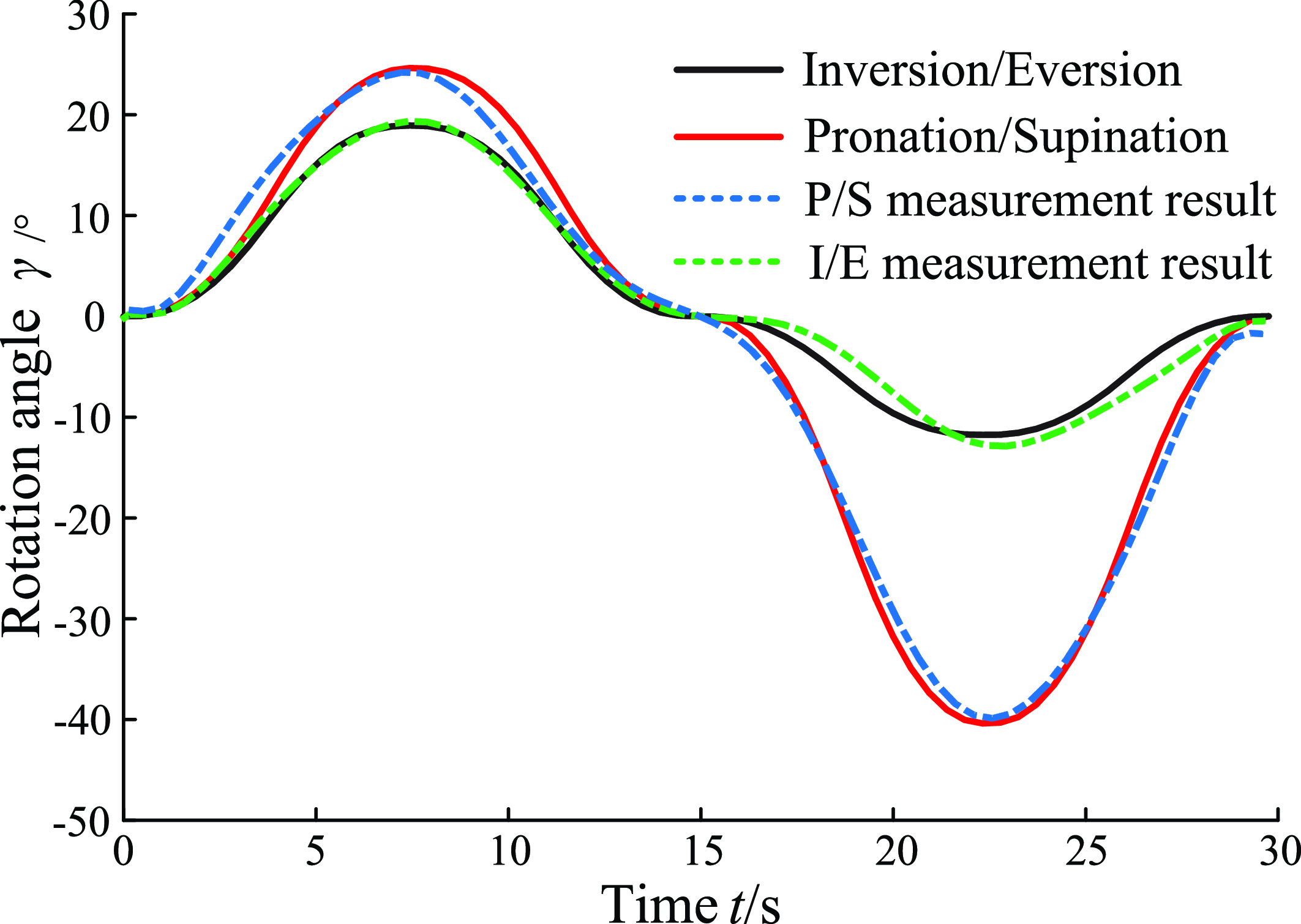
Figure 19. Rotation angle of the mechanism.
6. Conclusions
Based on the study of the characteristics of ankle joint motion, this paper proposes a novel 3-UPU parallel mechanism that can rotate about any axis in the plane within a certain range. In other words, the mechanism can achieve non-fixed-point rotation around the instantaneous axis of the ankle joint, which is more suitable for rehabilitation than the characteristics of human ankle joint motion. Based on the characteristics of human anatomy and the range of motion of the ankle joint, the size parameters of the mechanism are analyzed and the genetic algorithm is used to optimize the mechanism parameters. The rehabilitation rotation angle of the mechanism is planned, and kinematic simulation is performed. The experimental verification of the above rehabilitation training method shows that the mechanism can meet the requirements of ankle joint rehabilitation. Since the motion axis of the human ankle joint is not fixed, our goal in future research work is to predict the instantaneous rotation axis of the human ankle joint during motion so that the ankle joint rehabilitation robot can move around this axis to make the rehabilitation effect safer and more reliable.
Author contributions
Xuechan Chen and Ziming Chen conceived and designed the study. Yu Guo and Jianxun Fan conducted data gathering. Chaoyang Ji and Chao Xin performed experiments. Xuechan Chen wrote the article.
Financial support
The research is supported by National Natural Science Foundation of China (Grant No. 51775474).
Competing interests
The authors declare no competing financial interests.
Ethical approval
The study has been approved by the Ethics Committee of Qinhuangdao First Hospital.


