


Introduction
For several decades, dielectric resonator antennas (DRA) are being studied and experimented with by many researchers and have found their way into several technologies which require a high level of antenna performance such as broadcast systems, geosynchronous earth orbit, satellite communications, navigation systems, and a large variety of radar systems. Although several existing metallic antennas like microstrip patch antennae can be utilized in such applications, at very high frequencies, and under hostile temperature conditions, these antennas undergo metallic losses [Reference Keyrouz and Caratelli1]. There are two main enthralling reasons for the DRAs at mm-wave frequency spectrum replacing patch antennas with DRAs [Reference McAllister, Andrew Long and Conway2–Reference Kranenburg and Long4]. Firstly, the DRAs have higher antenna efficiency than patch antennas; antenna efficiency is not as important at low frequencies (microwave frequencies), but it is significant at mm-wave frequencies due to high propagation losses, necessitating high-performance transmitters and receivers. The fractional bandwidth is the second reason why DRAs are more appealing in mm-wave applications. It also has a small size, ease of excitation is lightweight, and low cost. The DRA consists of a dielectric substance that has low ohmic losses and uses a high dielectric constant material. This reduces dielectric and metallic losses resulting in high radiation efficiency, high integration, and increased impedance bandwidth [Reference Keyrouz and Caratelli1]. A rectangular dielectric resonator antenna (RDRA) is easy to fabricate and has a greater degree of freedom [Reference Petosa, Simons, Siushansian, Ittipiboon and Cuhaci5]. The 3D DRA structure allows designers to have greater freedom while designing than the 2D and 1D structures (like monopole antennas and microstrip patch antennas) [Reference Leung, Lim and Fang6]. It can have different shapes like rectangular, cylindrical, hemispherical, triangular, and cross-shaped [Reference McAllister, Andrew Long and Conway2, Reference Gupta and Gangwar7, Reference Nor, Jamaluddin, Kamarudin and Khalily8]. These features make DRA reliable at high frequencies such as millimeter waves for many wireless applications and a possible contender for 5G applications [Reference Wang, Denidni, Zeng and Wei9]. Despite such interesting features, the gain performance of the dielectric antenna can be further enhanced for long-range wireless communication systems. For instance, in an underground mine wireless communication, the propagation properties are marked by a high level of oxygen absorption and rain attenuation. In such cases, high-gain antennas are required to compensate for attenuation effects and loss [Reference Coulibaly, Nedil, Talbi and Denidni10]. With the enhanced gain, DRAs can prove fruitful in such situations as they provide high radiation efficiency due to negligible conductor losses.
DRA has a size proportional to $\lambda _0/\sqrt {\varepsilon _r}$ [Reference Keyrouz and Caratelli1]. Here, λ 0 is the free-space wavelength, and $\varepsilon _r$
 is the dielectric constant of the dielectric resonator (DR). DRAs provide high radiation efficiency since they exhibit no inherent conductor loss due to their material properties. This property is useful for millimeter (mm) wave antennas, as metal fabrication has a high loss rate and hence lower radiation efficiency. Transmission lines can be coupled with DRAs which makes them suitable for integration into different planar transmission lines. The fabrication process is achievable by varying the position of the DRA with respect to the line. By choosing the appropriate resonator parameters, the operating bandwidth of a DRA can be varied over a wide range. The dielectric parameter has the potential to vary the bandwidth of the lower-order modes of a DRA by a fraction of a percent to about 20% or more. It has also been successful to use multiple modes radiating identically in hybrid combinations. DRAs can be excited in different modes to produce different radiation characteristics. Slots can be introduced in the DRA structure to enhance the bandwidth due to changes in the effective dielectric constant of the resonator (Table 1).
Table 1. List of abbreviation

This paper provides an overview of various gain enhancement techniques, underlying principles, comparisons, and various challenges in the design. Furthermore, filtering DRA (FDRA) is also discussed which involves DRA along with a filter. In addition to a comprehensive collection of gain enhancement methods, from the year 1983 to the latest ones; this paper shows outcomes and identifies the key research areas for future work. This will serve as a guide to the reader for further research work on DRA.
The key contributions of this survey are:
• A detailed survey, evolution, and analysis of various emerging gain enhancement techniques of DRA are presented.
• Realization aspects of recent gain enhancements techniques for different types of DRA along with their respective characteristics are discussed.
• A detailed comparison of gain enhancement techniques with respect to the key parameters of DRA including gain, bandwidth, resonant frequency, and so on is covered.
• Key takeaways and research challenges in respective approaches are also discussed.
Section “Gain enhancement techniques” discusses the gain enhancement techniques with comparison, section “Comparison of gain enhancement techniques” discusses the comparison of various techniques based on performance parameters, and section “Conclusions and future scope” provides the conclusion and future scope in terms of challenges and research directions. The paper focuses more on the mm-wave frequency band in the later part as it is still an unexplored frequency range and is a future for the 5G wireless communication domain.
Gain enhancement techniques
Due to the challenges and expectations of the continuously rising traffic explosion, substantial research and development are being done on fifth-generation (5G) wireless communication technology. The most effective strategy to fulfill the needs of the 5G communication system is to increase bandwidth. Switching to a higher-frequency band is necessary to handle the high data rate needed, which is in the gigabits per second range (Gbps) [Reference Feng, Li, Jin, Su and Chen11]. The fundamental issue with a higher-frequency band, however, is the substantial path loss in short-range communication by the short wavelengths. To overcome the difficulties of high path loss and increase the high-frequency transmission range, high-gain antennas are required [Reference Rappaport, Xing, MacCartney, Molisch, Mellios and Zhang12]. Hence, to use DRAs as a possible replacement for traditional antennas, it is important to discuss their gain enhancement. A circularly periodic electromagnetic band gap (EBG) substrate can be used to enhance the gain of the antenna as reported by Denidni et al. [Reference Denidni, Coulibaly and Boutayeb13]. Most techniques aim at reducing side lobe levels thereby increasing gain. High gain hybrid DRA with surface-mounted horn proposed by Elboushi et al. [Reference Elboushi and Sebak14] is one such method. Various other techniques were researched [Reference Guha, Banerjee, Kumar and Antar15–Reference Cicchetti, Faraone, Miozzi, Ravanelli and Testa20] which resulted in gain enhancement as well. Using uniaxial anisotropic dielectric material inside the DR, the gain was increased as suggested by Fakhte et al. [Reference Fakhte, Oraizi and Matekovits21]. The experimental study on stacked DRA as proposed by Petosa and Thirakoune [Reference Petosa and Thirakoune22] can be used where two dielectric cylinders are stacked with an air gap between them. Such studies guide RF front-end designers to design antennae of the required configuration. Figure 1 shows the broad categories of gain enhancement techniques.

Fig. 1. A broad categorization of various gain enhancement techniques in DRA.
Stacked DRA
Stacking the different dielectric layers in the DRA is one of the promising gain enhancement techniques mentioned in [Reference Pan and Zheng23–Reference Mongia25]. Pan et al. [Reference Pan and Zheng23] investigated a wideband, high-gain DRA. The antenna was made up of two dielectric layers with different permittivity and excited by a rectangular slot in the middle as depicted in Fig. 2(a). It has a bottom rectangular dielectric layer with low permittivity and a dielectric constant of 2.2 and a top rectangular dielectric layer with high permittivity and a dielectric constant of 15. The sides of the two layers are of the same length L, with different heights h1 and h2. The dimensions are set so that L > h1 + h2. This provides a low profile at the resonant frequency as explained by Essel et al. [Reference Esselle24] and Mongia et al. [Reference Mongia25]. The height variation causes the DRA to resonate in higher-order mode, thus improving the gain and radiation efficiency. A microstrip-coupled slot built on a substrate with a permittivity of εr feeds the antenna at its center. The top ground plane is created with a rectangular slot and a 50 Ω microstrip feedline. A stub of length lm is etched on the other side of the substrate, as illustrated in Fig. 2(a). The DRA is x-polarized because it uses a y-directed slot for excitation. The high permittivity layer has ɛr = 15 whereas the low permittivity layer has ɛr = 2.2. The two layers result in two resonant modes in the passband. The TEy 111 mode at lower (4.35 GHz) frequencies causes the first resonance, whereas the TEy 131 mode at higher (5.4 GHz) frequencies causes the second. The $TE_{121}^y$ mode cannot be excited because it requires a minimum E-field at the slot location. In the boresight direction (θ = 0°), co-polarized fields are stronger than cross-polarized fields. The results confirm that the lateral and longitudinal resonances are responsible for the lower and upper modes, respectively. This means the two modes may be tuned independently, which is ideal for antenna construction. The work done by Pan et al. [Reference Pan and Zheng23] was inspired by a double-layered high permittivity DR investigated by Hwang et al. [Reference Hwang, Zhang, Luk and Yung26] operating at a 1.8 GHz. The measured results show that the double-layered DR antenna achieved by stacking two layers of high permittivity (ɛr = 38, 80) has a 1.2 dB gain enhancement and 25% height reduction over a single-layered antenna. They also suggested that loss in radiation efficiency can be recovered by this introduction of a higher permittivity layer. The analysis provided by these two papers using stacking methodology provides an insight that by properly choosing the dielectric constants of the two layers as well as by changing the dimension ratios of height appropriately, wide impedance bandwidth up to 40% and an increase in gain up to 9 dBi is obtained. Similar stacking of uniaxial anisotropic material (UAM) with many layers inside a DR was proposed in [Reference Fakhte, Oraizi and Matekovits21, Reference Yarga, Sertel and Volakis27, Reference Yarga, Sertel and Volakis28]. Fakhte et al. [Reference Fakhte, Oraizi and Matekovits21] used a UAM inside the DR rectangular prism to improve the directivity of DRA functioning in the fundamental TEy 111 radiating mode. This is a unique technique for obtaining higher gain as compared to higher-order mode generation. The use of UAMs in RDRA improves the radiation from the side walls as compared to the top walls. This improves the boresight radiation pattern and hence the gain. Figure 2(b) shows the fabricated stacked DRA [Reference Fakhte, Oraizi and Matekovits21]. The permittivity tensor for a uniaxial anisotropic medium is given by equation (1).

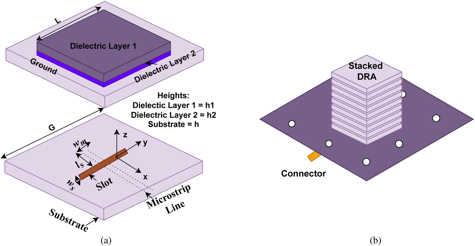
Fig. 2. (a) High gain stacked DRA with microstrip coupled slot. (b) An anisotropic stacked DRA.
The concept of extraordinary and ordinary waves was explained in literature [Reference Lee and Kong29–Reference Pettis31]. Lowering the value of ɛz in comparison to the value of εx significantly increases the electromagnetic (EM) field leakage from the sidewalls of ADRA as compared to the top wall. Anisotropic DRA's impedance bandwidth and gain are enhanced when εz is reduced, compared to isotropic DRAs. The drop in the effective dielectric constant of the structure is responsible for the anisotropic DRA's increased impedance bandwidth [Reference Fakhte and Oraizi32]. The directivity of rectangular DRA in the boresight direction is increased considerably. Similar anisotropic DRAs were explored by Yarga et al. in their research work suggesting better gain using hybrid and higher-order mode excitation [Reference Yarga, Sertel and Volakis27, Reference Yarga, Sertel and Volakis28]. An interesting way of using the Yagi–Uda concept was introduced in DRA by Kishk [Reference Kishk33] where different discs of the same dielectric material were connected through a nick-like structure of the same material. This reduced the cost as the material used was of the same dielectric constant and increased the directivity of the antenna. A two-, three-, and four-discs arrangement excited by the coaxial probe is shown in Fig. 3(a). The gain enhancement of 2.7 dBi for two discs and 3.6 dBi for three discs was obtained in [Reference Kishk33]. The gain was found to be enhanced in stacked DRAs with respect to non-stacked DRAs. Another novel technique of improvisation was proposed by Xia et al. where a comb-like structure is placed above DRA to provide circular polarization [Reference Xia and Leung34]. However, the trapezoidal geometry of the DR along with the comb-like structure provides a stable radiation pattern in the boresight direction thereby increasing the gain up to 8.3 dBic. Stacking in trapezoidal geometry is shown in Fig. 3(b). Furthermore, Table 2 shows the performance comparison of some stacked DRA antennas. The graph of Fig. 4 shows briefly the increment in gain due to stacking. Despite all these advantages, stacked antennas do have limitations of being costly and bulky, and hence new techniques to enhance gain need to be explored.

Fig. 3. (a) Stacked arrangement of DRA for enhanced gain. (b) Stacked trapezoidal comb-like DR for CP.

Fig. 4. Gain (dBi) increment using stacked arrangement of DRA.
Table 2. Performance comparison of stacked DRAs

Excitation of DRA in higher-order modes
Another important technique for gain enhancement in DRA is by exciting the DRA with higher-order modes. Higher-order modes were initially used to increase the impedance bandwidth of DRA [Reference Bit-Babik, Di Nallo and Faraone35–Reference De Young and Long37]. The technique of using higher permittivity material for stacking was suggested for gain enhancement in the planar antenna of inverted F type by Hwang et al. [Reference Hwang, Zhang, Zheng and Lo38] and the same concept is applied to DRA and the results are achieved. However, Petosa et al. investigated the use of higher-order mode excitation for gain enhancement using the FDTD simulation method [Reference Petosa, Thirakoune and Ittipiboon39]. A simple dielectric waveguide model for predicting radiation patterns was proposed by Petosa et al. where up to 5 dBi gain enhancement was obtained at higher-order modes as compared to the fundamental mode of excitation [Reference Petosa and Thirakoune22]. For a rectangular DRA having a dielectric constant of ɛr and dimensions of a, b, and d and with a perfect infinite ground plane, the resonant frequency of fmn and TExδmn mode can be predicted using equations (2)–(4) given by Mongia et al. [Reference Mongia and Bhartia40, Reference Mongia and Ittipiboon41].


where kx, ky, and kz are wavenumbers in x, y, and z directions respectively and k o is free space wavenumber. The speed of light is represented by c. The value of wave numbers essentially depends on the mode of operation. When the antenna is functioning in its higher-order modes, the size and separation distance between the edges expand to several wave lengths [Reference Khan, Ihsan, Fazal, Malik, Sheikh and Salman42]. As the electric field varies more quickly, the currents suffer a 180° phase shift in neighboring half cycles, which leads to high side lobe levels and distorted radiation patterns, while having high gain. Equation (6) [Reference Khan, Ihsan, Fazal, Malik, Sheikh and Salman42] shows the relationship between gain (G) and effective aperture area and wavelength.

where Aeff is the effective aperture area and λ is the wavelength of the antenna. Therefore, exciting an antenna in a higher-order mode essentially increases the electrical area and hence the gain [Reference Perron, Denidni and Sebak16]. The dimensions of an RDRA considered by Mongia [Reference Mongia and Ittipiboon41] are as per Fig. 5. Ali et al. [Reference Ali, Jamaluddin, Gaya and Rahim43] used a simple RDRA but excited it in TExδ 15 obtaining a high gain of 10.5 dBi. This was achieved by strategically using an aperture coupled feed line.

Fig. 5. RDRA with dimensions a, b, and d.
Higher-order excitation to receive a stable radiation pattern and improved gain was achieved by Liang et al. [Reference Liang and Denidni44] by strategically developing an H-shaped DRA with a trapezoidal conformal feed. They selected a DR of a higher dielectric constant of 9.8 for improved bandwidth and better radiation patterns. A similar H-shape of the DRA was proposed by Fakhte et al. [Reference Fakhte, Oraizi and Matekovits45] by inserting grooves in the side wall of the DRA. The groove causes an increase in the magnitude of the electrical field, thus increasing the bore sight gain of the antenna to 9.6 dBi. Abdulmajid et al. [Reference Abdulmajid, Khamas and Zhang46] in their paper excited a hemispherical DRA (HDRA) in TE 511 and TE 711 by using a cross-slot feeding mechanism. Though the HDRA is multilayer, this methodology is used here for wider bandwidth and not for enhanced gain. This antenna is unique as it provides a gain of approximately 9.5 dBi in the mm-wave frequency range. Such high gain at mm-wave frequency is desirable for forthcoming 5G technology applications. The multilayer permittivities of 9, 4, and 3 for the inner, middle, and outer layers, respectively, were utilized. The gain is maintained by coating the DRA with two layers to provide a multi-stage transition and gives wide bandwidth. Hu et al. [Reference Hu, Pan, Zhang and Zheng47] proposed a FDRA using a microstrip-coupled slot from the bottom and open stub of the microstrip feedline. This FDRA was designed to provide two radiation nulls at band edges for filtering which was an extended work of the antenna proposed in [Reference Pan, Hu, Zhang and Zheng48]. In this paper [Reference Hu, Pan, Zhang and Zheng47], Hu et al. elaborated on the design with all four phases and proved the gain enhancement up to 4 dBi through separate slots in the feeding mechanism, thereby exciting the RDRA in higher mode. The development stages are shown in Fig. 6(i). It can be seen from Fig. 6(i–c), that the antenna III with slots in the coupled line causes the boresight gain to decrease significantly although the filtering functionality improved. Two parallel strips which improve the suppression in the upper stopband are introduced in antenna IV. This suppression helps improve the gain. Three resonant modes at 5, 5.7, and 6.07 GHz are obtained due to fundamental TE 111, TE 311, and hybrid Hybrid Electromagnetic (HEM) modes, respectively. Also, bending the DRA and exciting it with two sets of microstrip-coupled slots with an interval distance of a wavelength forms a 2 × 1 array, improving the gain to 9.05 dBi. Figure 6(ii) [Reference Hu, Pan, Zhang and Zheng47] shows this change in the configuration of antenna IV given in Fig. 6(i) [Reference Hu, Pan, Zhang and Zheng47].

Fig. 6. (i) Transition in the antenna design. (ii) Change in antenna IV (Fig. 6(i)) with a bend in DRA and two feeding slots.
Pan et al. [Reference Pan, Leung and Luk49] derived through their experimentations that when a slot for cross-coupling microstrip feed is placed at the center of the DRA, a TEpqr mode can be excited only if p, q, and r all are odd numbers. For the odd-mode solution, the tangential electric field is antisymmetric about the middle plane which is an equivalent electric wall [Reference Koul50]. In [Reference Pan, Leung and Luk49], two DRAs were proposed to operate at TE 115 and TE 119 higher modes for mm-wave frequency of 24 GHz with a gain of 5.8 and 6.3 dBi for respective modes. The characteristic equations of the wavenumbers and for the TEpqr mode were derived using Marcatili's approximation technique as mentioned by Mongia et al. [Reference Mongia and Bhartia40, Reference Mongia and Ittipiboon41]. The isolation of modes can be obtained by carefully selecting DRA dimensions. A reconfigurable CP antenna was proposed in [Reference Ji, Ge, Li and Wang51] with wideband and better gain. By removing a concentric annular column from its interior, the DRA element allows unidirectional HEM 110 mode and omnidirectional TM 010 mode to operate in the same wide band, the center-loaded metal post also aids in improving resistance and significant matching of the TM 010 resonance. Table 3 compares the performance of the antennas with higher-order mode excitation for enhanced gain. Figure 7 shows the graph indicating an increase in gain due to higher-order mode excitation. Though the higher-order mode excitation helps in improving circular polarization and percentage bandwidth, high power loss is reported in antennas which is a topic of concern. Frequency-selective surface (FSS) superstrates can be explored to overcome these limitations.

Fig. 7. Gain (dBi) increment using higher mode excitation.
Table 3. Performance comparison of higher-order mode excited DRAs

FSS superstrate
FSS are a growing research topic that provides spatially varying EM waves for selective frequency [Reference Anwar, Mao and Ning52]. FSS merely exhibits an electrical response for a particular frequency [Reference Glybovski, Tretyakov, Belov, Kivshar and Simovski53–Reference Vardaxoglou55]. FSS due to highly reflective surfaces increases the directivity considerably [Reference Munk56]. FSS [Reference Kapoor, Mishra and Kumar57–Reference Lalbakhsh, Afzal, Esselle and Smith59] use metamaterials which are planar forms of meta-surfaces offering better and novel solutions as they shape the radiated wave by offering phase modulation which approaches 2π. According to Huygen's principle, exciting both electric and magnetic surface currents allows for unidirectional scattering providing maximum efficiency [Reference Pfeiffer and Grbic60, Reference Tsilipakos, Koschny and Soukoulis61]. Though FSS is not directly described as a gain enhancement technique, it eventually increases gain since gain (G) is related to directivity (D) and efficiency (η) by the relation given in equation (7).

Kesavan et al. [Reference Kesavan, Mantash, Zaid and Denidni62] suggested a DRA with FSS for mm-wave frequency band application. They proposed a cantilever-type four-layered FSS unit cell. The cantilevers are axe shaped with connecting lines cut out in stainless steel material which sits on the top layer and the bottom layer is a ground plane. Both layers are separated by epoxy resin glue. The CDRA acts as a radiating source and the FSS structure is placed on top of this CDRA separated by Rohacell foam. The DRA is excited using a coaxial probe. This FSS arrangement works as a parabolic reflector [Reference Niroo-Jazi and Denidni63] increasing the gain up to 6 dBi. Figure 8 [Reference Kesavan, Mantash, Zaid and Denidni62] explains this arrangement. Belen et al. [Reference Belen, Mahouti and Palandöken64] proposed a DRA loaded using FSS structure using 3D printing technology. The FSS inclusion provides moderate gain as well as reduces the antenna size considerably. Rana et al. [Reference Rana, Chatterjee and Parui65] proposed a design with bandpass multilayer FSS to increase the gain of simple RDRA up to 3.6 dBi from normal RDRA design. Rana et al. [Reference Rana, Chatterjee and Parui66] also proposed a dual-polarized RDRA with the same CRSF FSS superstrate. This antenna was found to be highly directive and dual polarization was applied using two microstrip lines exciting the DRA orthogonally. For an increase in gain, three split-ring resonators have been connected as a unit cell of an FSS which is polarization independent providing a gain of 8.9 dBi. For the circularly polarized (CP) antenna, Akbari et al. [Reference Akbari, Gupta, Farahani, Sebak and Denidni67] proposed and designed a wave frequency RDRA fed by coupling an X-shaped slot with one layer of FSS superstrate at the top to increase the gain to 8.5 dBi. Three layers of FSS provided a gain of 14.2 dBi. The increased gain is a result of a highly directive beam obtained in a broadside direction due to the reflected waves through the air gap being transmitted by the superstrate. The tuning of DRA, the air gap of the X-shaped slot, and the superstrate also play an important part in achieving the desired results. Such CP high-gain antennas can be effective in satellite communication applications. FSS are combined in MIMO antenna designs [Reference Karimian, Kesavan, Nedil and Denidni68] at 60 GHz with low mutual coupling. For low mutual coupling in MIMO antennas, high isolation and low envelope correlation coefficient (ECC) are required [Reference Costa, Lima, Medeiros and Fernandes69]. ECC is related to diversity gain [Reference Costa, Lima, Medeiros and Fernandes69] as per equation (8). The FSS acts as a wall separation between two DRAs [Reference Karimian, Kesavan, Nedil and Denidni68] to give high isolation. Also, the simulation gain is reported to increase by 1.5 dBi with respect to the reference antenna. In [Reference Kakhki, Mousavirazi and Denidni70], Kakhki et al. reported a gain improvement of 4.2 dBi over the unloaded antenna by loading three layers of FSS horizontally in front of the ridge gap DRA in the H-plane. The resonant frequency of the antenna is 28 GHz and each layer of FSS consists of a 2 × 3 array of FSS unit cells. Chauhan et al. [Reference Chauhan, Rajput and Mukherjee71] reported a DRA for X-band applications with corrugated circular ring-shaped single-layer double-sided meta superstrate loaded on the DRA to enhance the peak gain to 11.9 dBi. A CDRA-based MIMO antenna is proposed by Das et al. [Reference Das, Sahu, Sharma, Gangwar and Sharawi72] with multi-directional pattern diversity offering high isolation. The gain of this configuration is improved by 2.3 dBi which might be possible due to diverse radiation patterns in four directions as well as the low value of ECC. A coaxial RDRA for C-band applications [Reference Pandey, Chauhan, Killamsety and Mukherjee73] achieves a gain of 14 dBi by using an Metamaterial (MTM) superstrate of 50 cell units. The simple arrangement achieves a stable radiation pattern and circular polarization suitable for radar and satellite communication applications. In [Reference Mukherjee, Patel and Mukherjee74], the complementary split-ring resonators (CSRR) shaped slot is etched on HDRA and ground plane where current distribution which is out of phase lowers down. This results in current cancelation along the CSRR and hence reduces the cross-polar component of the radiation pattern thereby offering a gain of 6 dBi. Table 4 shows the performance comparison of FSS superstrate DRAs. Figure 9 shows the graph with an increase in gain using the FSS superstrate technique.


Fig. 8. Axe-shaped cantilever-based FSS structure.

Fig. 9. Gain (dBi) increment using frequency-selective surfaces (FSS).
Table 4. Performance comparison of FSS superstrate DRAs

Electromagnetic band gap (EBG)
EBG is known to enhance the gain of the antenna by suppressing the unwanted surface wave [Reference Adas, De Flaviis and Alexopoulos75–Reference McKinzie, Nair, Thrasher, Smith, Hughes and Parisi78]. It is experimentally proved by McKinzie et al. [Reference McKinzie, Nair, Thrasher, Smith, Hughes and Parisi78] that edge currents can be greatly reduced by EBG structure, and ground plane currents can be restricted. By restricting surface wave propagation, less diffraction occurs in non-broadside directions and broadside gain is increased. EBG has widely been used for beam tilting and enhancing the electrical properties of a DRA [Reference Mabrouk, Nedil, Denidni and Sebak79]. A reconfigurable radiation pattern in the azimuth plane was achieved in [Reference Mabrouk, Nedil, Denidni and Sebak79] by strategically placing six EBG sectors around the DRA. Circular-shaped EBG sectors were incorporated as they provide higher directivity as compared to other shapes [Reference Al-Hassan80, Reference Mabrouk, E'qab, Nedil and Denidni81] and their performance is better in terms of EM wave suppression. This two-port EBG configured DRA [Reference Mabrouk, Nedil, Denidni and Sebak79] provides a gain of 4.2 dBi and is pattern reconfigurable as a pin diode is used for switching on and off the EBG sectors for the reconfigurability in azimuth plane at 60 GHz. The placement of EBG sectors around DRA is shown in Fig. 10 [Reference Mabrouk, Nedil, Denidni and Sebak79].

Fig. 10. Arrangement of six EBG sectors around DR.
Mushroom-shaped EBG DRA for radar applications was proposed [Reference Abdelaal and Kishk82] and a comparison of non-EBG DRA and EBG DRA is presented. DRA with EBG improves the gain and a total gain of 6.7 dBi is achieved. Similarly, a 2.4 dBi improvement in gain was proposed [Reference Al-Hassan80] by placing the EBG structure 1 mm below the CDRA for mm-wave applications. Again, circular patch-based EBG [Reference Al-Hassan80, Reference Mabrouk, E'qab, Nedil and Denidni81] was utilized and connected to the ground plane using vias. The design of DRA and EBG unit cells is optimized to lower the back radiation significantly [Reference Mu'ath, Denidni and Sebak83] thereby blocking the surface waves from propagating and hence increasing the radiation efficiency. Here, the EBG unit cells act as perfect magnetic conductors which cause impinging of surface waves propagating along the antenna substrates and diffracted at the edges thereby improving radiation efficiency and gain. Coulibaly et al. [Reference Coulibaly, Boutayeb, Denidni and Talbi84] suggested a new EBG substrate for CDRA for gain enhancement up to 3 dBi. Again, a circular-shaped EBG unit cell [Reference Al-Hassan80, Reference Mabrouk, E'qab, Nedil and Denidni81] was utilized because in circular geometries located at the center of the source, the bandgap effect remains the same in all radial directions. So, the circular EBG was introduced on the substrate and connected to the ground plane through vias. Xia and Leung [Reference Xia and Leung85] reported a unique uniplanar EBG structure positioned around RDRA for gain enhancement of more than 3.5 dBi. The novelty of this design is that the EBG is placed around RDRA as shown in Fig. 11 which suppresses the surface wave, and its stopband features improve the radiation aperture of the antenna. The uniplanar design of the EBG unit cell consists of a patterned square patch in the center and four L-shaped patches at the corners for C-band applications. This feature of manipulation of the radiation patterns in antennas is explained in detail by Lee et al. [Reference Lee, Yeo and Mittra86]. They investigated the impediment in EM waves due to EBG materials for distinct types of antennas. Such structures enhance gain by suppressing the propagated wave at a particular frequency. In [Reference Sinha, Killamsetty and Mukherjee87] EBG as a split-ring resonator structure is placed in the near field region of RDRA for gain enhancement. 5 × 5 array unit cell with a periodicity of λ 0/6 to λ 0/8 was placed above simple RDRA. The height of the superstrate is adjusted using parametric analysis which suppresses the RDRA as the first resonance of RDRA due to the loading effect and an increase in the number of unit cells increases the coupling and results in higher gain. This arrangement results in gain enhancement up to 1.5 dBi giving the final gain plot as 8 dBi. Gain enhancement techniques have gained much importance, especially for mm-wave as DRA's zero conductor loss feature makes it a suitable candidate for this frequency [Reference Long, McAllister and Shen88, Reference Jazi and Denidni89]. Using a circular patch [Reference Al-Hassan80, Reference Mabrouk, E'qab, Nedil and Denidni81] EBG for 60 GHz mm-wave frequencies gain enhancement was significantly achieved for DRAs [Reference Mu'ath, Denidni and Sebak17, Reference Al-Alem and Kishk90, Reference Attia and Kishk91]. In [Reference Mu'ath, Denidni and Sebak17], a circular patch-based EBG structure is placed around CDRA like the one presented in [Reference Xia and Leung85]. The distance between two EBG unit cells was calculated from equation (9) [Reference Ramaccia, Toscano and Bilotti92]:

where ω is the gap width between two EBG unit cells and D is the period. No wave propagation is allowed in the frequency band and a large current induced in the circular patch lattice causes significant gain enhancement.

Fig. 11. RDRA with uniplanar EBG.
In [Reference Al-Alem and Kishk90], the EBG structure is used to feed the DRA and eliminate parasitic radiation from the feed line. A boresight gain of 12.6 dBi is reported. In [Reference Attia and Kishk91], a printed ridge gap waveguide structure is used to feed the CDRA and acts as EBG to enhance the gain of CDRA. These techniques not only reduce the size of the antenna but also make DRA a successful antenna at mm-wave frequencies. A unique design is recently proposed in [Reference Tong, Hauke, Yang and Leung93] where a compact and broad CP DRA using dielectric vias is designed. Filling a perforated printed circuit board (PCB) substrate with barium strontium titanate with a dielectric constant of 20 creates the dielectric vias. The electrical size of the DRA is lowered because of the highly effective dielectric constant of the dielectric vias-loaded PCB substrate. The DRA structure's layout of dielectric and air vias enables for spreading of the mode resonant frequencies of various radiating modes. This design incorporates a third higher-order mode into the passband, resulting in enhanced gain, impedance bandwidth, and axial ratio bandwidth. In [Reference Ma, Zheng, Pan and Chen94] the EBG structure is introduced along the four side-wall boundaries of a particular dielectric region on a PCB to create a DR with fake EM boundaries. A printed array of periodic upside-down mushroom-type unit cells is used to create the EBG structure. The suggested DR can support both standard DR modes and dense dielectric patch cavity modes, according to the resonant-mode analysis. For developing a completely integrated DRA, a substrate-integrated gap waveguide transmission line is included in the proposed structure to excite the DR. Table 5 presents some of the comparative results of DRA using EBG structures and Fig. 12 shows the graph of the increase in gain using EBG structures. Even though EBG structures aid in increasing gain, they can be used with other methods to enhance the antenna's performance metrics. Hybrid antennas will be covered in the next part for better performance.

Fig. 12. Gain (dBi) increment using electromagnetic bandgap (EBG) structures.
Table 5. Performance comparison of EBG superstrate DRAs

Hybrid DRA
Another resort to increasing the gain of DRA is to incorporate the gain-enhancing properties of other antennas and form a hybrid antenna system. The disadvantage of such antennas can be the bulkier size. As seen in the stacked DRA section, Yagi–Uda designs were incorporated for increasing the gain [Reference Kishk33]. However, this design increases fabrication complexities [Reference Kramer, Djerafi and Wu95]. In [Reference Gupta and Parihar96–Reference Baldazzi, Al-Rawi, Cicchetti, Smolders, Testa, van Coevorden Moreno and Caratelli98], the DRAs are placed inside a horn for gain enhancement. In [Reference Gupta and Parihar96], RDRA is placed inside a short aluminum horn as was described in [Reference Esselle97] for gain improvement and to make the antenna less bulky. Two microstrip lines are used for exciting the antenna [Reference Gupta and Parihar96] as well as stub loading is incorporated for bandwidth enhancement. The SMSH utilized here increases the directivity of the beam thereby increasing the boresight gain to 12.2 dBi. A very interesting and novel concept to increase the directivity and boresight gain to 11.3 dBi was proposed and investigated in [Reference Baldazzi, Al-Rawi, Cicchetti, Smolders, Testa, van Coevorden Moreno and Caratelli98] where a CDRA is placed inside a truncated conical horn made of plastic material. It is interesting to note that a non-conductive horn improves the gain by focusing the power in the boresight direction of the antenna. They also compared the solid conical horn with a notch-induced conical horn and found better results.
In [Reference Denidni, Coulibaly and Boutayeb13], a copper-based hollow conical horn was placed around CDRA excited in its dominant HEM 11 mode. In essence, the horn around DRA increases the directivity, and thereby increased gain is measured. Antennas as proposed in [Reference Varshney, Pandey and Yaduvanshi99] provide circular polarization with a gain of around 2 dBi. High gain for millimeter waves in such antennas along with circular polarization could be challenging. In [Reference Agouzoul, Nedil, Coulibaly, Denidni, Mabrouk and Talbi100], an excellent gain of 16.71 dBi at 60 GHz is achieved using a cylindrical DR, a rectangular slot fed by a microstrip line, and stacked metallic strips [Reference Moustafa and Jecko101, Reference Rodes, Diblanc, Arnaud, Monediere and Jecko102]. Metallic strips are placed at an optimized half wavelength height from the ground plane like FSS or EBG superstrates. Here it is important to note that the reflectivity is increased by selecting the optimized width of the microstrips as 0.7 mm. This causes the main lobe to be directed in a broadside direction. A different perspective of hybrid antennas was presented in [Reference Lin and Wu103] where a hollow is created in the DRA structure which is filled with water. The uneven structure of DRA consists of the lower layer as an irregular rectangular dielectric, an upper layer as a cylindrical dielectric with a center hollow part, a hybrid part of water, and a metal strip. The upper portion of DRA in the upper band has the most impact on the E-field distribution. The upper portion of DRA has a new structure because of the hybrid technology plan. Furthermore, this portion creates a high relative permittivity. The smaller cylindrical portion (water) forms the HEM 111 mode at 2.75 GHz based only on the E-field properties of water. A new resonant mode is produced because of the interaction between the high order mode (TE 113) of the DRA and the mode of water. As a result, loading water activates the additional resonant mode at the upper band, which concentrates the energy of the upper section of DRA. The antenna's radiation performance in the z-axis direction is improved by the combination with high relative permittivity, which serves as a director and raises gain values from 6.01 to 8.33 dBic. Furthermore, by modifying the water volume, the gain values of HDRA at the upper band can be individually regulated as needed. Here, the water level is changed to achieve high gain operation, which has an impact on the combination part's relative permittivity. This increases gain in the upper band by 1.32 dB. In [Reference Zhang, Deng, Li, Sun and Guo104], a single chip-based array for terahertz frequency is investigated. A 2 × 2 array element with a single DRA placed on top of it increases the gain from 0.1 to 8.6 dBi at 340 GHz. Table 6 shows the performance comparison of some of the hybrid DRAs, and Fig. 13 provides a plot of the increase in gain using hybrid antennas.

Fig. 13. Gain (dBi) increment using hybrid antenna structures.
Table 6. Performance comparison of hybrid DRAs

DRA array
Gain enhancement can be achieved by cascading multiple antenna stages, for example, using antenna arrays. This not only scales up the overall size but also degrades the isolation. Isolation issues can be resolved using DRA arrays. An array of cross-shaped DRAs is presented in [Reference Elkarkraoui, Delisle, Hakem and Coulibaly105] which are excited using aperture coupling as shown in Fig. 14. A stub is introduced at the end of the microstrip line for better matching and this structure of nine-cross DRAs provides a gain of 15.5 dBi for mm-wave which is of great significance. A novel 4 × 10 array DRA structure was proposed and investigated for the frequency range of 90–110 GHz [Reference Zandieh, Abdellatif, Taeb and Safavi-Naeini106]. They incorporated a low-loss silicon image guide power splitter for feeding the array. This complex design [Reference Zandieh, Abdellatif, Taeb and Safavi-Naeini106] has overcome fabrication issues by incorporating the use of optical lithography and the silicon micromachining technique. The antenna theory concepts [Reference Mukherjee, Patel and Mukherjee107] are utilized in [Reference Gangwar, Ranjan and Aigal108], and four-element triangular DRA is utilized to achieve a gain of 4.76 dBi. In [Reference Yang, Ke and Chen109], a bidirectional DRA array using a back-to-back quasi-Yagi antenna configuration is proposed where the DR is excited at higher-order mode increasing the gain by 1.8 dBi. Though this is an array configuration, it should be noted that higher-order mode excitation results in gain enhancement. In [Reference Qureshi, Klymyshyn, Tayfeh, Mazhar, Börner and Mohr110], Qureshi et al. suggested a cost-effective solution by creating cavities in acrylic templates and filling them with dielectric materials to build a polymer-based DRA array layer. This array-type antenna provides a gain of more than 10.5 dBi as reported by the authors. A similar approach of DRA array with a back cavity was reported in [Reference Chen, Shen, Liu, Ye, Qi, Yao, Yu and Chen111] with an enhanced gain of 17.2 dBi. In [Reference Abdalmalak, Althuwayb, Lee, Botello, Falcón-Gómez, García-Castillo and García-Muñoz112], without the use of power dividers, transitions, or launchers, a high-gain linear DRA array with a standing-wave feed network is proposed. In comparison to traditional feeding techniques, the suggested feed approach had a relatively high gain and outstanding efficiency. The manufacture of a four-element array using affordable 3D printing technology yielded a peak measured gain of 14 dBi. Table 7 shows the performance comparison of some of the DRA arrays and Fig. 15 provides a plot of the increase in gain using array antennas.

Fig. 14. Cross-shaped DRA array (AXDRA).

Fig. 15. Gain (dBi) increment using DRA arrays.
Table 7. Performance comparison of DRA arrays

Comparison of gain enhancement techniques
Different techniques to enhance gain have been presented in section “Gain enhancement techniques”. It can be deduced from the study that an array of DRA with moderate gain can be used for adequate area coverage as mentioned by Baldazzi et al. [Reference Baldazzi, Al-Rawi, Cicchetti, Smolders, Testa, van Coevorden Moreno and Caratelli98] and Varshney et al. [Reference Varshney, Pandey and Yaduvanshi99]. For miniaturized applications, FSS and EBG structures can be incorporated for gain enhancement. Radiation pattern significantly improves with the help of hybrid DRAs increasing the gain. Stacking is the simplest technique that not only improves gain but also bandwidth but is bulkier and costly. A detailed comparison of each technique is presented in tabular form for better vision and understanding. Table 8 presents the range of gain and percentage bandwidth obtained from each technique as discussed.
Table 8. Comparison of gain enhancement techniques

Conclusions and future scope
In this paper, we present a comprehensive comparison of different gain enhancement techniques in DRAs. Various techniques for stacked DRA and higher-order mode excitation are found to achieve higher gains up to 10 dBi. However, the stacking of DRA makes it more costly and bulky, thereby suited for very limited applications. The higher-order mode excitation increases the power losses, making it unsuitable for mm-wave frequencies. For mm-wave and higher frequencies FSS and EBG, superstrate/structures are utilized. However, the complexities of these structures and the excitation of surface waves that leads to lower bandwidth cannot be denied. FSS can provide a gain enhancement of up to 15.5 dBi [Reference Akbari, Gupta, Farahani, Sebak and Denidni67] whereas EBG structures can achieve a gain enhancement of up to 12.6 dBi [Reference Al-Alem and Kishk90]. To maintain the performance parameters, hybrid antennas can be deployed to achieve a gain enhancement of up to 16.7 dBi [Reference Agouzoul, Nedil, Coulibaly, Denidni, Mabrouk and Talbi100]. Hybrid antennas being bulkier open the scope for space-constrained research. If the size is not a priority, the DRA array techniques can be explored in MIMO applications for gain enhancement and to provide the desired performance parameters. A gain of up to 19 dBi [Reference Zandieh, Abdellatif, Taeb and Safavi-Naeini106] has been reported for DRA arrays. We have focused on the mm-wave frequency band in the later part, as it is still an unexplored frequency range and is a future for the 5G wireless communication domain. Despite several advantages, DRAs also have certain limitations including the physical characteristics of the material, their fabrication, and their placement restriction on the PCB. To address this, DRAs are also being explored at the nanometer level [Reference Abdalmalak, Althuwayb, Lee, Botello, Falcón-Gómez, García-Castillo and García-Muñoz112] that are suitable for wireless communication. The frequency range can be improved by using DRA arrays along with ease of fabrication and manufacturing techniques. Miniaturization and ease of manufacturing make DRAs practically viable and useful for massive MIMO [Reference Varshney and Sahana113, Reference Malekar, Raut, Shevada and Kumar114]. Moreover, the utilization of a single mask for fabrication and combining the Complementary Metal Oxide Semiconductor(CMOS) technology in DRA fabrication [Reference Hou, Hong, Goh, Chen, Xiong, Hu and Madihian115] can be useful in the development of DRA structures.
Acknowledgements
The survey could not be completed without valuable inputs from Dr. Paritosh Peshwe, Assistant Professor, Indian Institute of Information Technology, Nagpur, India. We would also like to thank the reviewers for their useful comments and suggestions. This paper is a part of the fellowship of the Visvesveraya Ph.D. scheme (part-time), MIETY, Government of India.
Conflict of interest
None.
 Ankita H. Harkare pursued her Bachelor of Engineering (electronics and communication) and Masters in Engineering (VLSI design) from Shri Ramdeobaba College of Engineering and Management, Nagpur, India in 2009 and 2014, respectively. She is currently pursuing her Ph.D. from the Indian Institute of Information Technology, Nagpur, India. She worked as a system engineer at Tata Consultancy Services after completion of graduation. She is currently working as an assistant professor at Shri Ramdeobaba College of Engineering and Management, Nagpur, India. She has attended and presented papers at eight national and international conferences and published 11 journal papers to date. She has three published patents, three copyright, and one book chapter in Springer Series to her credit. She has delivered expert lectures in the field of VLSI design and conducted workshops related to the same. Her current research interest is antenna design. She is a life member of ISTE and IAENG.
 Dr. Ashwin G. Kothari is currently working as an associate professor in the Electronics and Communication Engineering Department of Visvesvaraya National Institute of Technology, Nagpur, India from where he has received his Ph.D. in 2010. He is also one of the coordinators for the Center of Excellence of Commbedded Systems: Hybridization of Communications and Embedded Systems established as a World Bank-assisted project of TEQIP 1.2.1. Applications of rough set-based signal processing are his special interest. He has authored several publications and has contributed book chapters for reputed publications. He has 25+ years of experience in teaching and research. He has produced eight Ph.D.s so far and is still guiding five Ph.D.s under his supervision. He has been a resource person for many seminars, invited talks, workshops, etc. He has eight filed patents and worked on industry collaborative projects with industries like Tektronix, Mathworks, NI, HCIT, SAMEER Mumbai, etc.
 Ankit A. Bhurane is currently working as an assistant professor in the Department of Electronics and Communication, Indian Institute of Information Technology Nagpur. He received his B.E. in electronics and communication, M.Tech. in electronics, and Ph.D. in 2008, 2011, and 2016, respectively, from SGBAU University, SGGS Nanded, and IIT Bombay. He has published papers in various international conferences and journals. He also has published a patent registered in the Indian Patent Office. His research interests include biomedical signal processing, scalable video coding, and green communication.


