


Introduction
In recent years, extensive research has been conducted on 5G wireless communication with the aim of achieving higher data rates and wider bandwidth [Reference Wang, Nan and Liu1, Reference Zada, Shah and Yoo2]. This technology offers numerous advantages, including increased consistency, reduced latency, and the ability to create smaller wireless devices [Reference Khan, Sehrai, Khan, Khan, Ahmad, Ali, Arif, Memon and Khan3, Reference Hassan, Hussain, Khan, Rashid and Bhatti4]. To support the implementation of 5G, the Federal Communications Commission (FCC) has designated specific frequency bands ranging from 3 to 300 GHz, which researchers have classified into two categories: sub-6 GHz (<6 GHz) and millimeter wave (mmWave) band (>24 GHz) [Reference Guo, Cui, Li and Sun5–Reference Kiani, Altaf, Abdullah, Muhammad, Shoaib, Anjum, Damaševičius and Blažauskas7]. Designing antennas for 5G mmWave communications requires careful consideration of various factors, including impedance bandwidth, antenna gain, radiation pattern, antenna size, and challenges such as atmospheric attenuation, all of which increase the complexity of the design process [Reference Raheel, Altaf, Waheed, Kiani, Sehrai, Tubbal and Raad8, Reference Kamal, Yang, Kiani, Sehrai, Alibakhshikenari, Abdullah, Falcone, Limiti and Munir9]. Additionally, to achieve high channel capacity, the antenna system integrates with multiple-input multiple-output (MIMO) technology, which significantly enhances communication system performance [Reference Hassan, Zahid, Khan, Rashid, Rauf, Maqsood and Bhatti10]. However, achieving effective performance and low correlation values necessitates strong isolation between antenna elements and a compact size [Reference Li, Cheung, Wu and Yuk11, Reference Yuan, He, Hong, Han, Chen and Yuan12]. Several design methodologies can be employed to address this issue, including the use of defective ground structures (DGS), decoupling networks, neutralization lines, pattern diversity, and polarization diversity [Reference Sui and Wu13, Reference Alsariera, Zakaria and Awang Md Isa14].
Several antenna designs have been developed for 5G mmWave applications, offering improved radiation performance and dual-band capabilities. A mmWave MIMO antenna is introduced in [Reference Khan, Al Harbi, Kiani, Anis, Munir, Saeed, Iqbal, Ali, Alibakhshikenari and Dalarsson15]. The antenna exhibits dual-band and wide bandwidth characteristics, achieved by incorporating microstrip stubs onto the radiator. To mitigate the issue of high mutual, inter-element coupling in the MIMO antenna, a decoupling structure is positioned at the centre of the substrate. In paper [Reference Rosaline, Kumar, Upadhyay and Murshed16], a compact planar MIMO antenna designed for 5G mmWave applications is presented. The antenna elements are constructed with four strategically placed slits, aimed at enhancing the impedance bandwidth. Additionally, a plus-shaped decoupling structure is implemented between the four elements of the MIMO antenna, effectively improving isolation by up to −30 dB. A dual-band MIMO antenna, which operates within the 28 and 38 GHz mmWave frequency ranges, is presented in paper [Reference Aghoutane, Das, EL Ghzaoui, Madhav and El Faylali17]. The design consists of a solitary component, comprised of a square radiating element with spherical and semispherical slits that enable its dual-band operation. High isolation was achieved by designing a plus-shaped ground structure. In paper [Reference Kamal, Yang, Ren, Altaf, Kiani, Anjum, Iqbal, Asif and Saeed18], a MIMO antenna designed for 5G applications at a frequency of 28 GHz is presented. The desired impedance bandwidth is achieved through the design of five circular rings and a partial ground plane, which features a semicircle at its central location on the topside. To achieve high isolation, the radiating elements are arranged in an orthogonal orientation. In paper [Reference Desai, Bui, Patel, Upadhyaya, Byun and Nguyen19], a dual-band MIMO antenna operating at 25 and 34 GHz is presented, achieving approximately 85% transparency by combining AgHT-8 and Plexiglas materials. The antenna’s geometry enables dual-band operation, with AgHT-8 used to create the transparent conductive patch and ground, while Plexiglas serves as the substrate. In paper [Reference Sehrai, Abdullah, Altaf, Kiani, Muhammad, Tufail, Irfan, Glowacz and Rahman20], the authors presented a four-element tree-shaped patch antenna designed to operate within the frequency range of 23–40 GHz. The single radiating element comprises four arcs of varying sizes, which contribute to a wide impedance bandwidth and frequency tuning capability. The orthogonal arrangement of antenna elements provides high isolation. A MIMO antenna operating at 28 GHz frequency band is presented in paper [Reference Rahman, Ren, Altaf, Irfan, Abdullah, Muhammad, Anjum, Mursal and Alkahtani21]. The antenna’s ground plane is trimmed to enhance gain, while an additional semicircular ring is incorporated into the upper portion of the ground plane to improve impedance bandwidth. Moreover, the radiating elements are strategically arranged in an orthogonal configuration to achieve high isolation. Mutual coupling between the inter-elements of a MIMO antenna can present a significant challenge, particularly in the context of 5G bands. Addressing this issue [Reference Kamal, Yang, Ren, Altaf, Kiani, Anjum, Iqbal, Asif and Saeed18] introduces a technique to suppress inter-element coupling by positioning them in orthogonal orientation to minimize mutual coupling. The utilization of meta surface-based decoupling structure is also employed in paper [Reference Alibakhshikenari, Virdee, See, Abd-Alhameed, Falcone and Limiti22]. The decoupling structure is inserted between the radiating elements of a MIMO antenna with the purpose of blocking surface current waves induced over the antenna and reducing mutual coupling. The literature encompasses a multitude of techniques [Reference Marzouk, Ahmed and Shaalan23, Reference Du, Wang and Hu24] that offer outstanding methods for enhancing isolation between the radiating elements of MIMO antennas.
There has been a focus in the literature on designing compact, high-isolation MIMO antenna systems. However, there is still a need for research on wide impedance bandwidth. In this context, this paper proposes a four-element compact MIMO antenna system that combines wide impedance bandwidth with high isolation characteristics. The proposed design not only emphasizes the compactness of the patch but also aims to achieve significant bandwidth, enhanced gain, and isolation of less than −20 dB. This is accomplished through a careful consideration of the MIMO configuration, radiating elements, and a passive decoupling structure. These design features contribute to the desired bandwidth characteristics, high gain, and isolation performance.
Single-element design methodology
The design of the proposed single element started with the selection of Rogers RT/Duroid 5880 (tan(δ) = 0.0009,  ${\varepsilon _{\textrm{r}}}$ = 2.2) substrate with a thickness of 0.25 mm and copper thickness of 0.035 mm. Simulations were carried out using CST microwave studio 2020. A 50 Ω microstrip line was designed to feed the radiator.
The modeling process of the proposed antenna commenced with the integration of a T-shaped strip onto the 50 Ω feeding line, to which two microstrip lines were affixed at their terminal points and bent toward the feeding structure. Additionally, a DGS was designed on the bottom side of the substrate. The bent technique helps to achieve wide impedance bandwidth characteristics. At this stage, the antenna operates in the 24.8–37.3 GHz frequency bands, as shown in step 1 of Fig. 1. In step 2, two strip lines were added to the bent strips near their bottom ends, and another strip line was added to the partial ground plane to introduce a dual-band feature. In order to realize the intended design, two square-shaped elements were affixed to the remote extremities of the strip lines on the radiating element, and a rectangular opening was etched into the ground structure. The feeding structure was also tailored by adding a rectangular strip at its center to improve the impedance matching of these two frequency bands shown in step 3 of Fig. 1.
The proposed antenna layout offers two advantages in its design. First, the utilization of bent strip lines toward the T-shaped structure allows for a wider bandwidth within the desired frequency range. Second, the inclusion of two square-shaped strip lines affixed to the remote extremities of the bent strip lines on the radiating element introduces an additional frequency band near 48 GHz. The partial ground plane designed on the bottom side of the substrate provides improved isolation between the antenna elements and enhances impedance matching. These benefits result in a wider bandwidth, as discussed in the literature [Reference Du, Wang and Hu24]. The proposed partial ground plane incorporates a square-shaped slot located at the top center, and a thin microstrip line has been added at the bottom center of the slot, as shown in Fig. 1. These modifications serve to increase the antenna’s bandwidth. The proposed antenna has a compact size making it suitable for use in 5G devices operating in mmWave frequency ranges. The simulated reflection coefficients |S11| were less than −10 dB in the frequency ranges of 24.04–39.56 and 44.48–50.8 GHz. The proposed single-band antenna is shown in Fig. 2(a) and (b) with dimensions of 10 × 10 × 0.254 mm3 as mentioned in Table 1.

Figure 1. Single-element antenna (a) design steps, and (b) reflection coefficient |S11| (dB).

Figure 2. Proposed design of single-element antenna. (a) Top view, and (b) bottom view.
Table 1. Dimensions of the proposed dual-band antenna (All values are in “mm”)

Parametric analysis of single-element antenna
The physical dimensions of the proposed antenna were optimized through a parametric analysis. During this process, various parameters of the single-element antenna were adjusted to observe their behavior and optimize the antenna design. The parameter W 5 represents the width of the top strip line in the T-shaped structure placed on top of the feeding line. This parameter plays a crucial role in the antenna’s radiation, as shown in Fig. 3(a). During the tuning process, it was observed that the resonant frequencies could easily be shifted between 32–35 GHz and 47–48.4 GHz, resulting in changes in both bandwidth and return loss. As the value of W 5 decreases from 3.1 to 2.35 mm, the return losses improve for both resonant frequencies. Furthermore, decreasing the W 5 parameter also increases the bandwidth of the second resonant frequency. After careful optimization, W 5 was set to 2.35 mm, which provided optimum results for return loss and bandwidth. The parameter L 5 corresponds to the length of the same strip line, which plays a role in controlling the bandwidth of the first frequency band and frequency shifting of the second frequency band. Additionally, it helps decrease the return loss of both resonant frequencies. L 5 was adjusted within the range of 0.4–0.7 mm to achieve the desired resonant frequencies with improved reflection coefficient. Ultimately, L 5 was set to 0.4 mm, resulting in the widest bandwidth of nearly 15 GHz in the first frequency band and the least reflection coefficient of −35 dB at 48.4 GHz, as illustrated in Fig. 3(b). The parameter L 7 represents the length of the two square-shaped patches attached to the remote ends of the bent strip lines in the radiating element. It was observed that by tuning the length of these square-shaped patches, L 7 affects the resonant frequency and bandwidth of the first frequency band, as well as the return loss of the second frequency band. Optimal results were obtained at L 7 = 0.5 mm, where the return losses of the first frequency band were minimized, and its bandwidth was improved. Additionally, a wide bandwidth of 5.6 GHz was achieved at the 48 GHz frequency band, as shown in Fig. 3(c). The width of this square-shaped strip was also adjusted within the range of 0.2–0.5 mm, and its response is depicted in Fig. 3(d), illustrating the frequency shifting and improvement in the reflection coefficient of both frequency bands. After multiple iterations, the desired resonant frequencies were achieved by setting W 7 to 0.5 mm. The above-mentioned parameters, namely W 5, L 5, L 7, and W 7, primarily contribute to the coarse tuning of the dual-band frequencies, as previously mentioned. For the fine tuning of the single-element antenna, the parameter L 2 was adjusted within the range of 0.15–0.75 mm, as shown in Fig. 3(e). This parameter enabled careful control of the frequency range of the dual band. After optimization, it was observed that the desired frequency ranges of the dual-band (24.3–39.4 and 45.0–50.6) were achieved when L 2 was set to 0.75 mm. Additionally, the width W 2 of the same strip line was adjusted between the values of 1.14–1.44 mm and carefully optimized to W 2 = 1.14 mm for the desired dual-band frequency range. This adjustment ensured a perfect impedance match between the 50 Ω port and the radiating structure, as illustrated in Fig. 3(f).

Figure 3. Parametric analysis of single-element antenna. (a) Optimization of Parameter W5 (b) Optimization of Parameter L5 (c) Optimization of Parameter L7 (d) Optimization of Parameter W7 (e) Optimization of Parameter L2 and (f) Optimization of Parameter W2.
During the parametric analysis of the aforementioned parameters (W 5, L 5, L 7, W 7, L 2, and W 2), the gain and radiation efficiency of the single-element antenna were evaluated, as illustrated in Fig. 4(a) and (b). The gain of the single-element antenna varied between 3 and 4.5 dBi as the parameters were adjusted. Within the frequency range of 24.3–39.4 GHz, the antenna’s gain remained relatively stable. However, in the frequency range of 45.09–50.62 GHz, the maximum gain observed was 4.5 dBi, achieved when L 7 was set to 0.3 mm. Similarly, the radiation efficiency remained above 94% and 90% for the first and second frequency bands, respectively, during the adjustment of the parameters. This ensured that the selected values of W 5, L 5, L 7, W 7, L 2, and W 2 were optimal not only for return loss, bandwidth, and gain but also for achieving high radiation efficiency. The radiation efficiency of the single-element antenna ranged between 89% and 98.4%. The parametric analysis indicated that the proposed parameter values yielded high gain and radiation efficiency, as depicted in Fig. 4(a) and (b), respectively.

Figure 4. Study of the radiation properties of the single-element antenna. (a) Gain and (b) Radiation efficiency.
Measured results of single-element antenna
The single-element antenna was fabricated on Rogers RT/Duroid 5880 material, with a 2.4 mm end-launch connector attached to the antenna port, as presented in Fig. 5(a–d). It was tested at the Radio Frequency Testing Laboratory, located at Yildiz Technical University (Yildiz Teknik Universitesi) in Yildiz, Istanbul, Turkey. The results obtained through simulation are in substantial concurrence with the measurements. Figure 6 illustrates the experimental and simulated reflection coefficients |S11| (dB) of the designed single element antenna. The impedance bandwidth of the dual-band (24.37–39.44 and 45.09–50.62 GHz) is below −10 dB.

Figure 5. Fabricated model of proposed single element antenna. (a) Front view, (b) Back view, (c) Antenna front with connector, and (d) Antenna back with connector.

Figure 6. Comparison of simulation and experimental results of single-element antenna.
MIMO antenna design
The four-element MIMO antenna was designed using the fundamental model of a single-element antenna, as presented in Fig. 7(a). Numerous research papers in the literature emphasize the significance of antenna element placement and orientation in MIMO configurations [Reference Khan, Al Harbi, Kiani, Anis, Munir, Saeed, Iqbal, Ali, Alibakhshikenari and Dalarsson15, Reference Rosaline, Kumar, Upadhyay and Murshed16]. These papers validate, through simulations and measurements, that the optimal orientation for antenna element placement is orthogonal. This arrangement minimizes substrate space coverage and reduces mutual coupling between closely positioned antenna elements. Alternative orientations can result in higher mutual coupling or increased substrate coverage. In the proposed design, the antennas were placed in orthogonal symmetry, as shown in Fig. 7(a). The isolation at 25.5–32.5 GHz remained greater than −20 dB as presented in Fig. 7(b). To address this issue, a decoupling structure was introduced.

Figure 7. Proposed design of four-element antenna. (a) MIMO antenna without decoupling structure, and (b) Isolation characteristics without decoupling structure.
Design of the decoupling structure
The decoupling structure was designed by studying the surface current density at 28.5 GHz to identify the coupling of current between the antenna elements, as illustrated in Fig. 8. As shown in Fig. 8(a) and (b), weak coupling was observed between the diagonal antennas (ANT 1–3 and ANT 2–4). In order to mitigate this issue, a fan-shaped decoupling structure was integrated between the four elements of the MIMO antenna. The design of the decoupling structure begins by placing one thin strip arm, on the substrate’s top side, between each of the radiating elements of MIMO antenna. Each of these strip arms will help to block the surface waves which are induced over the nearby radiating antenna. Finally, a square-shaped patch is placed at the center of the substrate to join these four strip arms. Such decoupling structures are available in the literature [Reference Khan, Al Harbi, Kiani, Anis, Munir, Saeed, Iqbal, Ali, Alibakhshikenari and Dalarsson15, Reference Alibakhshikenari, Virdee, See, Abd-Alhameed, Falcone and Limiti22] which confirms that higher isolation between the antenna elements can be achieved by careful placement of microstrip lines between the antenna elements of any MIMO configuration. This design aids in reducing the current coupling between the diagonal antenna elements, specifically in the frequency band of 25.5–32.5 GHz, as demonstrated in Fig. 8(c–d). Consequently, this results in substantial isolation improvement, with values less than −20 dB, as displayed in Fig. 9(b). Figure 10 shows the geometrical dimensions of the proposed MIMO four-element antenna.

Figure 8. Surface current density (A/m) of the proposed MIMO four-element antenna at 28.5GHz. (a) ANT-1 without decoupling structure, (b) ANT-2 without decoupling structure, (c) ANT-1 with decoupling structure, and (d) ANT-2 with decoupling structure.

Figure 9. MIMO antenna structure. (a) Placement of a decoupling structure between the four-element antenna, and (b) Isolation characteristics after addition of the decoupling structure.

Figure 10. Geometrical dimensions of the four-element antenna.
Surface current distribution
The performance of the proposed antenna model was assessed through simulation of the distribution of surface currents at the resonant frequencies on Port 1, as depicted in Fig. 11. This helps visualize the active element participating in radiation. The dual-band operation is achieved through two different parts of the modeled antenna. When antenna 1 is excited, the maximum current density can be observed around it, as shown in Fig. 11(a–d). For the 24.37–39.44 GHz frequency band, the maximum current concentration is seen on the strip line on top of the feedline, as well as the two microstrip lines bent toward the feeding structure, as shown in Fig. 11(a–b). For the 45.09–50.62 GHz band, the maximum current density is seen on the T-shaped line attached to the feeding structure and the two L-shaped structures, as shown in Fig. 11(c–d). It is observed that the rectangular slot on the ground structure performs excellently in terms of current distribution. The fan-shaped decoupling structure has a substantial impact on the current coupling between the antenna elements, particularly in the frequency band ranging from 25.5G to 32.5GHz.

Figure 11. Surface current density of the MIMO four-element antenna at resonant frequencies. (a) 26 GHz, (b) 29.5 GHz, (c) 47 GHz, and (d) 49 GHz.
Gain comparison of simulated MIMO antenna
Figure 12 compares the gain of the proposed antenna with and without the decoupler, as determined by simulation. The results demonstrate that the decoupling structure reduces the gain values at lower frequencies, specifically in the range of 24.37–36.60 GHz. However, at higher frequencies, within the range of 36.70–39.44 and 45.09–50.62 GHz, the decoupling structure enhances the gain values.

Figure 12. Gain comparison of simulated MIMO antenna.
Results and discussions
Fabricated four-element MIMO antenna
The proposed 4 × 4 MIMO antenna was fabricated, and 2.4 mm end launch connectors were attached to the antenna ports as shown in Fig. 13. Finally, measurements were conducted to compare and verify its performance.

Figure 13. Fabricated model of proposed four-element MIMO antenna. (a) Front view, (b) Back view, and (c) MIMO antenna with 2.4-mm end launch connectors.
Scattering parameters
The transmission and reflection coefficients of the proposed antenna are evaluated using a vector network analyzer (VNA). For testing purposes, the VNA is attached to the first antenna, while the remaining antenna ports are terminated by 50 Ω terminators. The simulated and laboratory-measured data are compared in Fig. 14(a), and it can be seen that the simulated and laboratory-measured reflection coefficient |S11| (dB) show good similarity. The reflection coefficient |S33| (dB) of antenna 3 is also measured in a similar manner and compared with its simulated results. The dual-band (24.37–39.44 GHz and 45.09–50.62 GHz) reflection coefficients are less than −10 dB, and the measured bandwidths are 15.07 and 5.53 GHz for the first and second bands, respectively. Antennas 2 and 4 show similar results.

Figure 14. Comparison between simulation and laboratory-measured scattering parameters of the fabricated MIMO antenna. (a) Reflection coefficients, and (b) Transmission coefficients.
To test the transmission coefficients (|S21|, |S31|, |S41|, |S32|, |S42|, and |S43|), the VNA was connected to the two ports of the fabricated antenna while the remaining two ports were terminated with 50 Ω terminators. Figure 14(b) compares the simulated and measured transmission coefficients, showing that the decoupling structure has improved the isolation between the various ports of the MIMO system.
The comparison between simulation results and laboratory-measured data with regard to transmission and reflection coefficients is depicted. It is evident that both simulation and measurement exhibit a high degree of consistency. Minor discrepancies between the simulated results and the measured data in Fig. 14(a) and (b) are due to tolerances in the fabrication and measurement setup [Reference Liu, Weng, Cheung, Yuk and Foged25].
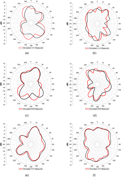
Figure 15. Comparison of simulated and experimental radiation patterns. (a) 26 GHz (E-plane), (b) 26 GHz (H-plane), (c) 29.5 GHz (E-plane), (d) 29.5 GHz (H-plane), (e) 45.1 GHz (E-plane), and (f) 45.1 GHz (H-plane).
Radiation patterns
The radiation patterns were measured in an anechoic chamber with dimensions of 9 × 5 × 5 m3. During this process, the first antenna port is excited, and the remaining ports are terminated using 50 Ω terminators. The radiation patterns of the proposed antenna, as obtained through both measurement and simulation, are illustrated in Fig. 15. For the 26 GHz frequency, the measured peak gain of 4.85 dBi occurs at 0°, while the lowest gain of −13.48 dBi occurs at 103°, as shown in Fig. 15(a). During the measurement of the 29.5GHz frequency band, the highest gain of 5.5 dBi occurs at 20° and the lowest gain of −11.05 dBi is observed at 265°, as shown in Fig. 15(c). For 45.1 GHz, the maximum gain of 6.9 dBi is seen at 15°, while the minimum gain of −8.8 dBi is observed at 270°, as shown in Fig. 15(e). The radiation characteristics were measured at Radio Frequency Testing Laboratory, Yildiz Technical University (Yildiz Teknik Universitesi), Yildiz, Istanbul, Turkey.
Gain and radiation efficiency
This section evaluates the radiation performance of the fabricated 4 × 4 MIMO antenna. The gain is measured using the substitution method, in which a calibrated laboratory antenna is connected to a source that transmits a signal with a frequency sweep from 26 to 29.5 GHz. The developed antenna under test receives the transmitted signals, and the path loss is normalized to 0 dB to provide the actual gain. The gains obtained from simulation and measurement are presented in Fig. 16(a) and exhibit a high degree of concurrence. For the frequency range of 26–29.5 GHz, the highest measured gain is 5.5 dBi at 29.5 GHz, while for the 45.09–46 GHz frequency range, the peak measured gain is 6.9 dBi at 45.1 GHz.

Figure 16. Radiation performance of proposed MIMO four-element antenna. (a) Gain (dBi), and (b) Radiation efficiency (%).
The antenna’s efficiency is evaluated within an anechoic chamber, where controlled power input is applied to Port 1 of the antenna. The resulting strength of the radiated electromagnetic field in the surrounding space is meticulously measured through a precisely calibrated measurement setup, facilitated by dedicated software [Reference Aghoutane, Das, EL Ghzaoui, Madhav and El Faylali17]. A comparison between its measured values and simulated results, as depicted in Fig. 16(b), reveals the antenna’s remarkable radiation efficiency, consistently exceeding 90% across the operational frequency bands.
Four-element MIMO antenna performance
Several parameters of the four-element antenna have been assessed to ensure its efficient performance. The following subsections present measurement of crucial parameters, including the envelope correlation coefficient (ECC), diversity gain (DG), CCL, and total active reflection coefficient (TARC).
Envelope correlation coefficient
The ECC is an important metric for evaluating the diversity performance of a MIMO setup, reflecting the inter-element coupling in the MIMO system. It is calculated using the radiation pattern [Reference Vaughan and Andersen26], as stated in equation (1):
 \begin{equation}ECC = {{|\mathop \int\!\!\!\int \nolimits {E_{\theta i}}.E_{\theta j}^{\rm{*}} + {\ }{E_{\varphi i}}.E_{\varphi j}^{\rm{*}}{|^2}d\Omega } \over {\mathop \int\!\!\!\int \nolimits {E_{\theta i}}.E_{\theta i}^{\rm{*}} + {\ }{E_{\varphi i}}.E_{\varphi i}^{\rm{*}}{\ }d\Omega {\ }\mathop \int\!\!\!\int \nolimits {E_{\theta j}}.E_{\theta j}^{\rm{*}} + {\ }E{\varphi _j}.E_{\varphi j}^{\rm{*}}d\Omega }}\end{equation}
In equation (1), “i” and “j” represent the ith and jth antenna in the MIMO configuration, respectively, while “θ” and “φ” represent the elevation and azimuthal planes, respectively. Using this equation, the values of ECC for the proposed MIMO antenna were measured and presented in Fig. 17(a). As depicted in this figure, the measured ECC exhibits a value of less than 0.007, demonstrating the efficient performance of the proposed antenna.

Figure 17. Comparison of simulated and experimental results. (a) ECC, and (b) DG.
Diversity Gain
In MIMO antenna systems, the use of a diversity scheme results in some power loss during transmission. The DG, as defined in equation (2) from paper [Reference Desai, Bui, Patel, Upadhyaya, Byun and Nguyen19], measures this power loss.
 \begin{equation}DG = 10 \times \sqrt {1 - |ECC{|^2}} \end{equation}
The DG of the proposed MIMO antenna is illustrated in Fig. 17(b), showing a value greater than 9.96. This highlights the superior performance of the antenna.
Channel Capacity Loss
The CCL is a crucial diversity parameter, defining the maximum attainable communication transmission rate. The proposed MIMO antenna’s CCL was measured by using equation (3) as outlined in paper [Reference Aghoutane, Das, EL Ghzaoui, Madhav and El Faylali17].
 \begin{equation}{C_{{\rm{loss}}}} = \; - {\rm{lo}}{{\rm{g}}_2}\det \left( {{\alpha ^R}} \right)\end{equation}
 \begin{equation*}Where,{\ }{\alpha ^R} = {\ }\left[ \begin{matrix}
{{\alpha _{11}}} & \cdots & {{\alpha _{14}}} \\
\vdots & \ddots & \vdots \\
{{\alpha _{41}}} & \cdots & {{\alpha _{44}}} \\
\end{matrix} \right]\end{equation*}
\begin{equation*}Where,{\ }{\alpha ^R} = {\ }\left[ \begin{matrix}
{{\alpha _{11}}} & \cdots & {{\alpha _{14}}} \\
\vdots & \ddots & \vdots \\
{{\alpha _{41}}} & \cdots & {{\alpha _{44}}} \\
\end{matrix} \right]\end{equation*} And  ${\alpha _{ii}} = 1 - \left( {\mathop \sum \limits_{j = 1}^N |{S_{ij}}{|^2}} \right)$
Also,  ${\alpha _{ij}} = {\ } - \left( {{S_{ij}}{\textrm{*}}{S_{ij}} + {\ }{S_{ji}}{\textrm{*}}{S_{ij}}} \right)$
The simulation results of the proposed MIMO antenna’s CCL are compared to the measured results, which are shown in Fig. 18(a). It can be observed from the figure that the measured results of CCL fall below 0.4 bits/s/Hz within the frequency band of 25–37 GHz, which is within the acceptable limit condition.

Figure 18. Comparison of simulation and laboratory-measured results. (a) CCL, and (b) TARC.
Total Active Reflection Coefficient
The TARC is a widely accepted metric for evaluating the radiation performance and bandwidth of a MIMO antenna. It is derived by comparing the incident input power to the reflected output power. The measurement of TARC is conducted through the use of S-parameters, as outlined in equation (4) of reference [Reference Chae, Oh and Park27]:
 \begin{equation}TARC = {{\sqrt {\mathop \sum \nolimits_{i = 1}^2 |{b_i}{|^2}} } \over {\sqrt {\mathop \sum \nolimits_{i = 1}^2 |{a_i}{|^2}} }} \end{equation}
Figure 18(b) presents the results of simulated and experimental TARC values. The data indicate exceptional performance of the proposed MIMO antenna, with TARC remaining below −10 dB across the entire operating band.
Comparison of proposed four-element antenna with existing literature
The proposed 4 × 4 MIMO antenna was compared to the MIMO antennas described in existing literature. The results of the comparison indicate that the proposed antenna is more compact in size when compared to [Reference Khan, Al Harbi, Kiani, Anis, Munir, Saeed, Iqbal, Ali, Alibakhshikenari and Dalarsson15, Reference Marzouk, Ahmed and Shaalan23], as shown in Table 2. Additionally, it has a higher gain compared to [Reference Rosaline, Kumar, Upadhyay and Murshed16, Reference Kamal, Yang, Ren, Altaf, Kiani, Anjum, Iqbal, Asif and Saeed18, Reference Desai, Bui, Patel, Upadhyaya, Byun and Nguyen19], and a wider bandwidth than any other antennas reported in Table 2. The radiation efficiency of the proposed antenna is also higher than [Reference Rosaline, Kumar, Upadhyay and Murshed16–Reference Rahman, Ren, Altaf, Irfan, Abdullah, Muhammad, Anjum, Mursal and Alkahtani21], and its isolation is greater than [Reference Desai, Bui, Patel, Upadhyaya, Byun and Nguyen19–Reference Rahman, Ren, Altaf, Irfan, Abdullah, Muhammad, Anjum, Mursal and Alkahtani21]. Furthermore, the edge-to-edge distance between the antenna elements in the MIMO configuration is less than [Reference Khan, Al Harbi, Kiani, Anis, Munir, Saeed, Iqbal, Ali, Alibakhshikenari and Dalarsson15, Reference Aghoutane, Das, EL Ghzaoui, Madhav and El Faylali17, Reference Kamal, Yang, Ren, Altaf, Kiani, Anjum, Iqbal, Asif and Saeed18, Reference Marzouk, Ahmed and Shaalan23]. Moreover, its levels of ECC and DG are comparable to those reported in the literature.
Table 2. Comparison of proposed MIMO antenna with existing literature

Conclusion
A dual-band, four-element, compact MIMO antenna operating at 24.37–39.44 GHz and 45.09–50.62 GHz has been proposed. At the operational frequencies, the simulation results exhibit a reflection coefficient less than −10 dB, which corresponds well with the actual measurements. It has a broad impedance bandwidth of 15.07 and 5.53 GHz at the operational frequency bands of 24.37–39.44 and 45.09–50.62 GHz, respectively. The use of a fan-shaped decoupler resulted in high isolation levels, with values less than −20 dB throughout all operational frequency bands. The antenna attains its highest gain levels of 4.85, 5.5, and 6.9 dBi, respectively, at frequencies of 26, 29.5, and 45.1 GHz. Radiation efficiency of more than 90% is reported throughout all working frequency ranges. The performance evaluation of the proposed antenna in terms of CCL, TARC, and DG, and ECC indicates its appropriateness for 5G mm device applications.
Competing interests
The authors declare none.

Ayyaz Ali obtained his B.Sc. degree in Telecommunication Engineering from Balochistan University of Information Technology, Engineering, and Management Sciences, Quetta, Pakistan, in 2013. Subsequently, he pursued further education and completed his M.Sc. degree in Electrical (Telecom) Engineering from the esteemed National University of Sciences and Technology, Islamabad, Pakistan, in 2017. At present, he is diligently working toward achieving his Ph.D. degree in Electrical (Telecom) Engineering at the National University of Sciences and Technology, Islamabad, Pakistan.

Maryam Rasool received her Ph.D. degree in Electrical Engineering from National University of Sciences and Technology (NUST) Islamabad, Pakistan, in 2022. She completed her BS and MS Electrical Engineering degrees from COMSATS University, Islamabad, Pakistan in 2012 and 2015 respectively with distinction. Her research interest includes MIMO, reconfigurable, and mmWave antenna designs.

Zeeshan Zahid received his M. Phil Electronics from Quaid-i-Azam University Islamabad, Pakistan and Ph.D. from Hanyang University, South Korea, in 2006 and 2018, respectively. He is currently working as Associate Professor at the Department of Electrical Engineering, National University of Sciences and Technology. His research area is antenna designing for mobile devices.

Imran Rashid did his B.E. in Electrical (Telecomm) Engineering from National University of Sciences and Technology, Pakistan, in 1999. He received his M.Sc. degree in Telecomm Engineering (Optical Communication) from D.T.U Denmark in 2004 and his Ph.D. in Mobile Communication from University of Manchester, UK in 2011. He has qualified four EC-Council certifications, i.e., Certified Ethical Hacker (CEH), Computer Hacking Forensic Investigator (CHFI), EC-Council Certified Security Analyst (ECSA) and ECCouncil Certified Incident Handler (ECIH). He is also a Certified ECCouncil Instructor (CEI) and has conducted numerous trainings. Currently, he is Chief Instructor (Engineering Wing), MCS at National University of Sciences and Technology, Pakistan. His research interests are Mobile and Wireless Communication, MIMO Systems, Compressed Sensing for MIMO OFDM systems, Massive MIMO Systems, M2M for Mobile systems, Cognitive Radio Networks, Cyber Security, and Information Assurance.

Adil Masood Siddiqui received his bachelor’s degree in tele-communications engineering from Military College of Signals, Rawalpindi Pakistan in 1994, master’s degree in electronics and telecommunication and PhD in electrical from University of Engineering and Technology, Lahore Pakistan, in 2005 and 2009, respectively. He is on the faculty of Military College of Signals, National University of Sciences and Technology since 2009. His research interest includes image registration, de-noising, image enhancement, and defogging. He has number of research publications at his credit.

Moazam Maqsood received his Ph.D. degree in 2013 from the University of Surrey, UK. He joined Institute of Space Technology (IST), Pakistan, in the same year and got involved in various research projects. He has a vast experience of managing projects both during his study period as well as in the professional career. He has worked with Surrey Satellite Technology Ltd., a leading satellite manufacturer. He also has experience of managing big projects and handling large teams. He has completed several R&D projects related to communication and systems design. He is the member of Wireless and Signal Processing (WiSP) Lab at IST. Moazam has so far supervised more than 30 students at BS and MS levels. He has co-authored more than 25 international publications for different conferences and reputable journals.

Farooq Ahmed Bhatti received his M.Sc. degree in Solid State Electronics and Physics from University of Punjab, Pakistan, in 1978, PhD degree in Microwave and Millimeter Waves from Shanghai University, China, in 1992 and Postdoctoral from University of Manchester in 2006. He is an active researcher and produced many publications in well-reputed journals and conferences. Currently, he is a faculty member and an associate professor at Military College of Signals, National University of Sciences & Technology. His research interests include design of RF/microwave and millimeter wave circuits, oscillators, power amplifiers, and antennas.


