Introduction
Light microscopes are widely used in research, routine laboratories, and teaching, and they often represent a substantial investment. Today many different types of microscopes exist, but they all have in common that the objective lens is regarded as the critical component for an optimal image [Reference Ross1]. The need for correction of optical aberrations is the main driver of the difference between low-cost objective lenses, as used by basic student microscopes, and the much more expensive objectives for advanced research microscopes. Microscopes are optical instruments which require regular maintenance, especially cleaning dirt and dust from optical surfaces along the light path [Reference Petrak and Waters2,Reference Deagle3]. The front lens of the objective is especially sensitive to dust and dirt, which can result in a markedly reduced resolution and suboptimal images. The price of sophisticated instruments, such as confocal or spinning disk microscopes, justifies professional maintenance, usually from the manufacturer. On the other hand, especially in teaching, limited budgets dictate that it is often the in-house staff that performs maintenance procedures. For this second scenario a series of excellent publications give very helpful and practical, step-by-step guidance, even if they do not all agree on all aspects, such as the recommended type of solvents that should be used to remove immersion oil or other fat from the lens [Reference Ross1–Reference James6]. This article describes a lens inspection procedure employing a common laser pointer.
Materials and Methods
Objective lenses should be inspected after each use, and oil should be removed form immersion objectives. Standard operating procedures (SOPs) call for regular removal of the objective and careful inspection using a stereo dissection microscope or, as an alternative, a magnifying glass or an inverted eyepiece [Reference Petrak and Waters2–Reference Eason and Méndez-Vilas4]. This allows light from a window or lamp to reflect off the lens, which reveals most irregularities on the surface. The lens should be clear and free of oil, dust, or other particles. One should screen for scratches on the surface or adherent contaminations. The lens seal should be checked for damage, which might have allowed oil to seep inside [Reference Petrak and Waters2]. Interestingly, examining the rear aperture of the objective is supposed to help identify dirt on the external lens surface because the internal lens organization produces a magnified image of these contaminations [Reference Rottenfussser5].
The frequent removal of oil from an immersion lens at the end of each session is likely to have a high propensity to be performed poorly or even wrongly, especially where novices may be at work, as in undergraduate teaching labs. The use of inadequate products, for example, abrasive tissues) or by employing an incorrect technique (for example, applying excessive direct pressure in a zig-zag pattern) has a high potential to damage the lens surface [Reference Ross1,Reference Rottenfussser5]. Importantly, while this may produce a degraded image quality, such as hazy images, the damage to the glass itself may not be immediately obvious and may be difficult to detect [Reference Petrak and Waters2].
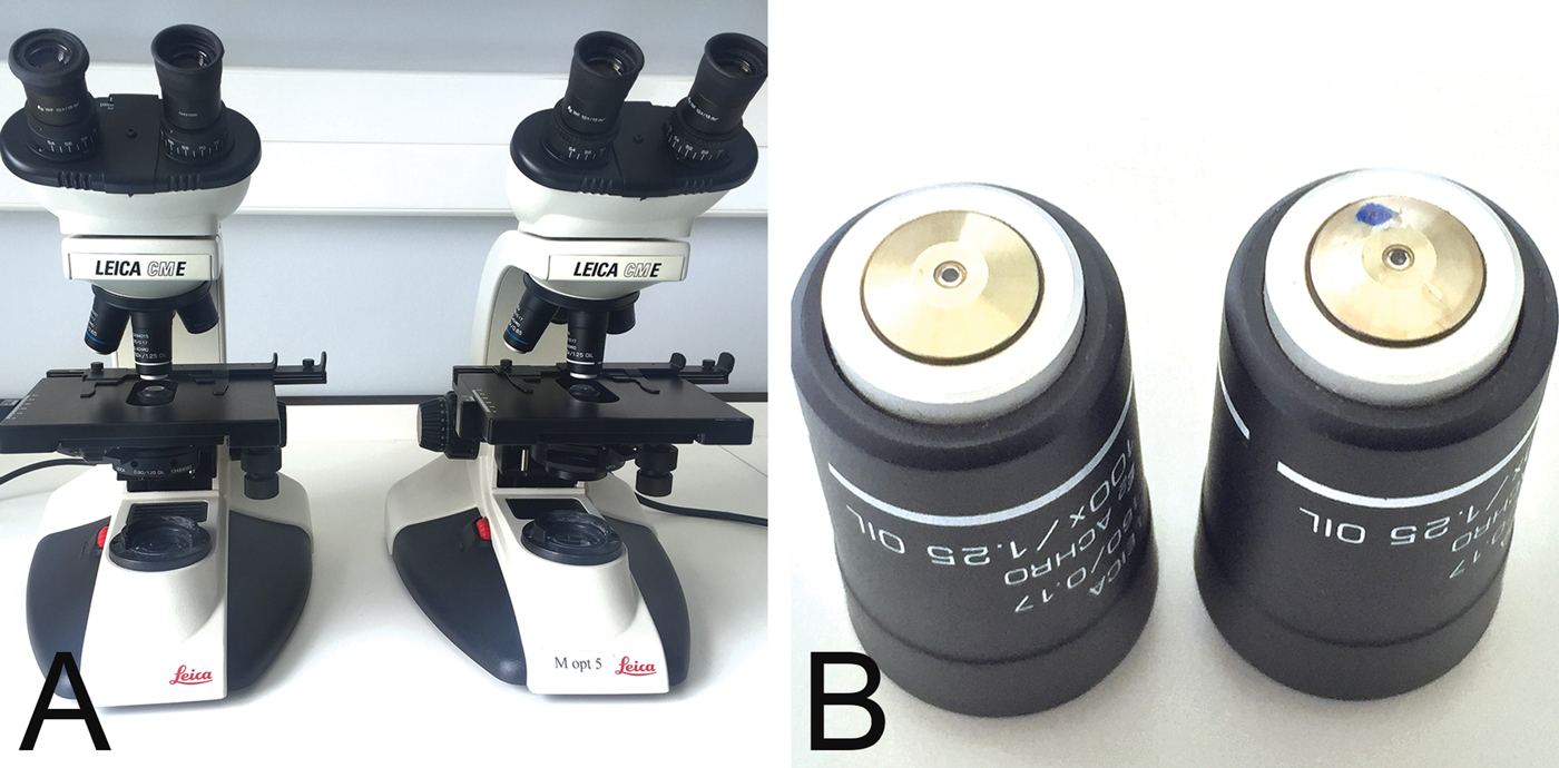
In our institution 25 light microscopes are used in practical classes to teach clinical microbiology to undergraduate students (Figure 1A). They are equipped with a 100×, achromat, oil-immersion objective (Figure 1B). Using a routine blood smear from a patient with malaria (Figure 2A), the quality of images is assessed at the end of term, as part of our maintenance and cleaning tasks.

Figure 1: Microscope and objective. Leica light microscope, model CME, for student teaching (A), with 100×/1.25, achromat, oil immersion objectives (B). A normal functioning objective is shown on the left and a damaged objective (blue dot) on the right.

Figure 2: Blood smear to assess microscope image. Routine blood smear from a patient with malaria showing numerous parasitized erythrocytes (50% parasitemia), one lymphocyte (bottom left), and one granulocyte (center). The same field of view was imaged using the same microscope after exchanging the objectives shown in Figure 1B: Normal image (A) and hazy image with damaged objective (B).
Results
One microscope produced a very poor, hazy image (Figure 2B). The quality of the remaining optical pathway was checked by swapping the objective with another microscope, which confirmed that the cause of the poor resolution was, indeed, the objective. The external lens was thoroughly cleaned, including the use of aggressive solvents, such as xylene and ether, without any improvement in the image. Inspection of the lens using an inverted eyepiece and a stereomicroscope did not reveal any apparent damage.
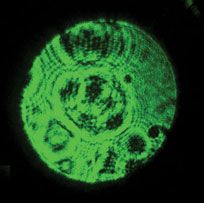
Based on the idea that any surface changes should be magnified at the reverse aperture [Reference Rottenfussser5], the light of a common laser pointer was used to test this. The front lens of the objective was aligned with the laser beam of the pointer (laser pointer JD-303, 532 nm, 20 mW; supplied by Alibaba), and the light exiting at the reverse aperture of the objective was projected onto a flat surface at a distance of half a meter (Figure 3). The image of an undamaged objective produces a normal image that shows a rather homogenous green projection (Figure 3A). The objective producing the poor image (Figure 3B), however, reveals markedly different patterns, with circular black rings and dark irregular areas, which move with the rotation of the objective. Using this technique with other objectives demonstrated that dirt or particles usually show up as well-defined, small, isolated dark spots, which disappear after cleaning.
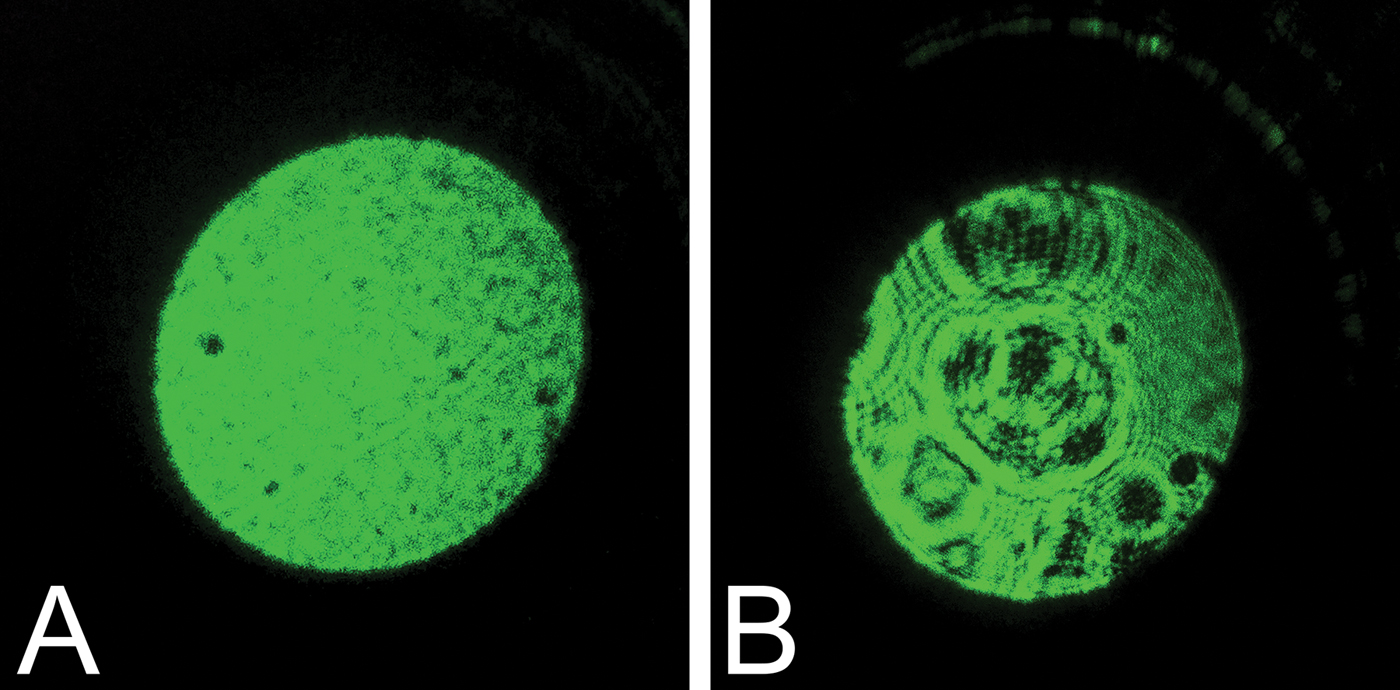
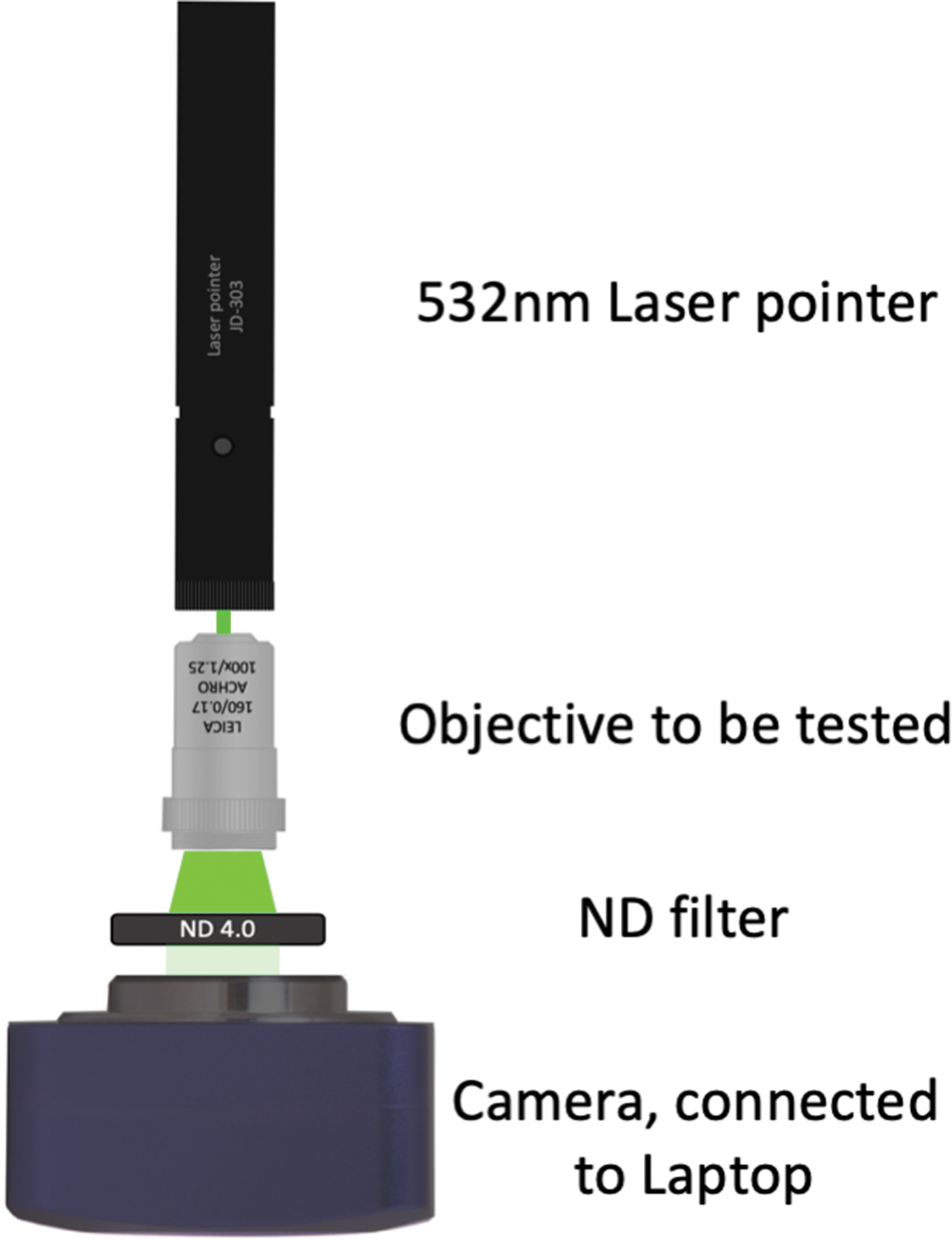
Figure 3: Projected image using a laser pointer. A common 20 mW, 532 nm laser pointer used for teaching was placed directly in front of the external lens of the objective, and the light exiting the reverse aperture was projected on a white wall, producing the images from a normal functioning objective (A) and from the damaged objective (B). Note that the white wall appears black because the image is underexposed due to the intensity of the laser light.
The exact nature of this effect is not completely clear, but likely the coherent, polarized light of the laser may be more sensitive to minute damage on the lens surface compared to natural light or light from a common room lamp. Laser pointers use an inexpensive diode laser and are available for 10–20 US$. This method could prove to be a simple and inexpensive way to check objective lenses for damage. Using a neutral-density (ND) filter and a common camera, which can be connected to a laptop, one can imagine the construction of a cheap device that would allow use of image analysis to provide results for this test (Figure 4).

Figure 4: Possible apparatus to measure the observed effect. Using a laser pointer (or only a laser diode), an appropriate neutral-density (ND) filter to avoid over-exposure at the camera, and a microscope (ocular) camera or similar. This setup would allow capture of images with simple imaging software, such as ImageJ (https://imagej.nih.gov/ij/features.html, accessed Aug. 7, 2019). The assumption would be that a perfect lens surface should produce an image where all pixels show equal values.
Conclusion
A laser pointer can be used to detect dirt and damage in light microscopy objective lenses. When cleaning and visual inspection fail to show any irregularity in a poor performing objective, a simple test with a laser pointer revealed damage unnoticed by other means.