


1. Introduction
Mobile robots have been widely used in service applications. According to the type of mobility, mobile robots can be classified as wheeled mobile robots, legged, tracked slip/skid [Reference Nodehi, Bruzzone and Fanghella1], and hybrid, [Reference Rubio, Valero and Llopis-Albert2, Reference Oliveira, Moreira and Silva3, Reference Russo and Ceccarelli4, Reference Maqsood, Afzal, Rafiq Mufti and Aslam5, Reference Luo, Shang, Wei and Ren6]. Currently, wheeled mobile robots have emerged as automated guided vehicles [Reference Sánchez, Sierra-García and Santos7, Reference Munoz-Ceballos and Suarez-Rivera8, Reference García, Yánez and Martínez9, Reference Godoy-Calvo, Lin-Yang, Vázquez-Martín and García-Cerezo10, Reference Castaño-Amorós, Páez-Ubieta, Gil and Puente11], mainly in logistics applications, [Reference Fragapane, de Koster, Sgarbossa and Strandhagen12, Reference Niloy, Shama, Chakrabortty, Ryan, Badal, Tasneem, Ahamed, Moyeen, Das, Ali, Islam and Saha13, Reference Zhang, Lin and Chen14, Reference Zacharia and Xidias15, Reference Llamazares, Molinos and Ocaña16] owing to their inherent advantages in terms of speed, smoothly, and energy saving while moving on flat ground. However, wheeled robots have poor mechanical adaptability and a low ability to avoid obstacles.
Several investigations have addressed different strategies to expand the trafficability capabilities of wheeled robots. There are two alternatives to improve its performance: (1) reconfiguration of the robot’s chassis adjusting its geometrical parameters, specifically width [Reference Song, Luo, Wei and Shang17, Reference Zhong, Guo, Li and Xu18] and height [Reference Ushimi19, Reference Attia20, Reference Niu, Wang and Shi21, Reference Yehezkel, Berman and Zarrouk22, Reference Coronel and Zarrouk23], and (2) wheel diameter variation.
Cosenza et al. presented an analysis of the chassis of a robot rover equipped with a “rocker-bogie” suspension. The tests cover a variety of terrains, including flat surfaces, inclined surfaces, and environments with obstacles. In addition, they examined the load distribution on the different wheels of the robot [Reference Cosenza, Niola, Pagano and Savino24].
Another comparable approach related to chassis manipulation is discussed by Karamipour, where the chassis undergoes a reconfiguration enabling it to expand or contract, thereby enhancing the robot’s overall displacement [Reference Karamipour, Dehkordi and Korayem25].
Regarding the reconfigurable wheeled robots that use soft materials, a folding wheel based on the variable diameter umbrella with origami pattern was introduced by Jeong and Lee. The umbrella structure can be manipulated for both compression and expansion movements under control. The wheel was made of paper, the sides of the umbrella structure were coated with a photopolymer resin, and the folds were covered with Ecoflex 00-30 elastomer. Experiments show that the wheel changes its diameter from $110$
to
$110$
to $240$
mm [Reference Banerjee, Kakde and Ren26].
$240$
mm [Reference Banerjee, Kakde and Ren26].
In ref. [Reference Jeong and Lee27], mobile robot with reconfigurable wheels based on Mohoko Tachibana’s twisted tower origami structure was presented; the authors built the wheel using flexible plastic sheets. The wheel reconfigures in width from $26$
to
$26$
to $48$
mm.
$48$
mm.
On the other hand, in ref. [Reference Lee, Kim, Kim, Koh and Cho28] an origami-inspired soft wheel in the shape of a water pump made of paper with polyimide film (Kapton), driven by an SMA coil spring, was presented. In experimental tests, the wheel showed a reconfiguration from $5.5$
to
$5.5$
to $7$
cm in height and from
$7$
cm in height and from $4.8$
to
$4.8$
to $5.5$
cm in width,
$5.5$
cm in width,
Similarly, in ref. [Reference Payne, Wamala, Abah, Thalhofer, Saeed, Bautista-Salinas, Horvath, Vasilyev, Roche, Pigula and Walsh29] the authors reported an origami pattern for the variable diameter wheel structure derived from the tessellated spherical water pump pattern. They fabricated the wheel from multiple PET film-based materials; experiments showed that the wheel expands from $45$
to
$45$
to $90$
mm.
$90$
mm.
The origami concept of developing transformable mechanisms using flexible materials is very interesting. However, this technique is impractical for mobile robots due to the materials from which the wheels are made, the low repeatability in manufacturing, and the complications of size wheel scaling.
One method that considerably improves the performance of robots on uneven terrain or increases the ability to overcome obstacles is to change the diameter of the wheel using rigid mechanisms.
Zheng et al. proposed a reconfigurable virtual wheel for displacement on regular terrain and obstacle-surmounting based on three planar linkage mechanisms connected to a triangular. The wheel is actuated by a single motor [Reference Zheng, Zhang, Hu, Yu, Song and Zhang30].
Additionally, Kim et al. presented the development of a mobile robot composed of wheels with variable diameters, incorporating three articulated legs. Through experimental demonstrations, they showed the robot’s capability to overcome obstacles of up to 130 mm. [Reference Kim, Jung, Kim, Cho and Chu31].
In ref. [Reference Zheng and Lee32], a reconfigurable wheeled robot with three gear-driven limbs has been presented. In experiments, the authors report that the robot overcomes obstacles up to $80$
mm, having a total height at rest of
$80$
mm, having a total height at rest of $115$
mm .
$115$
mm .
In ref. [Reference Chen, Wang, Ho, Ko, Lin and Lin33], a transformable wheeled robot consisting of six legs based on 4-bar mechanisms is presented; the robot can overcome obstacles up to $175$
mm with a transformation radius of 1.981.
$175$
mm with a transformation radius of 1.981.
Zhang et al. proposed a reconfigurable robot consisting of two adaptable symmetric wheels; each wheel can be extended by three sets of scissor-branched chain legs. They conducted experiments in an outdoor environment with the robot, which negotiated obstacles 250 mm high with a wheel radius of 82 mm. On stairs, the robot can climb steps 180 mm high and 300 mm wide, and overcome gaps of up to 170 mm [Reference Zhang, Yao, Wang, Liu, Xu and Zhao34].
In addition, in ref. [Reference Mardani, Ebrahimi and Alipour35] the author proposed a reconfigurable wheel composed of six rubber-coated Adaptive Prisms (6AP). They conducted virtual tests in simulations in which the robotic composite of four reconfigurable wheels achieved a diameter variation of $22$
to
$22$
to $58$
mm.
$58$
mm.
Reported research on reconfigurable wheels demonstrates that rigid bar mechanisms exhibit great versatility, allowing them to overcome obstacles with an average reconfiguration index of 1.5.
This research proposes the design and experimental evaluation of a reconfigurable wheel composed of four 4-bar retractable mechanisms. The article structure considers a reconfiguration index based on the number of 4-bar retractable mechanisms, the reconfiguration mechanism kinematic analysis, the study of the transformation process, and the experimental results.
2. Reconfiguration index
Most of the research related to reconfigurable wheels involves designs using three mechanisms to change the diameter of the wheel. Only three machines are used to optimise the space area. However, the robot only has three surface contact points for the mechanism.
Three retractable mechanisms are the minimum number to shape a regular polygon that allows the wheel to roll. The more retractable mechanisms the wheel has, the more it resembles a circle. In this section, the authors introduce a reconfiguration index based on the number of retractable mechanisms.
Figure 1 shows the conceptual proposal of the reconfigurable wheel, where the n-sided polygon is inscribed within a circle of radius equivalent to the apothem ( $r$
). The apothem
$r$
). The apothem $r$
coincides with the radius of the equivalent circle and the radius
$r$
coincides with the radius of the equivalent circle and the radius $R$
of reconfiguration at rest.
$R$
of reconfiguration at rest.
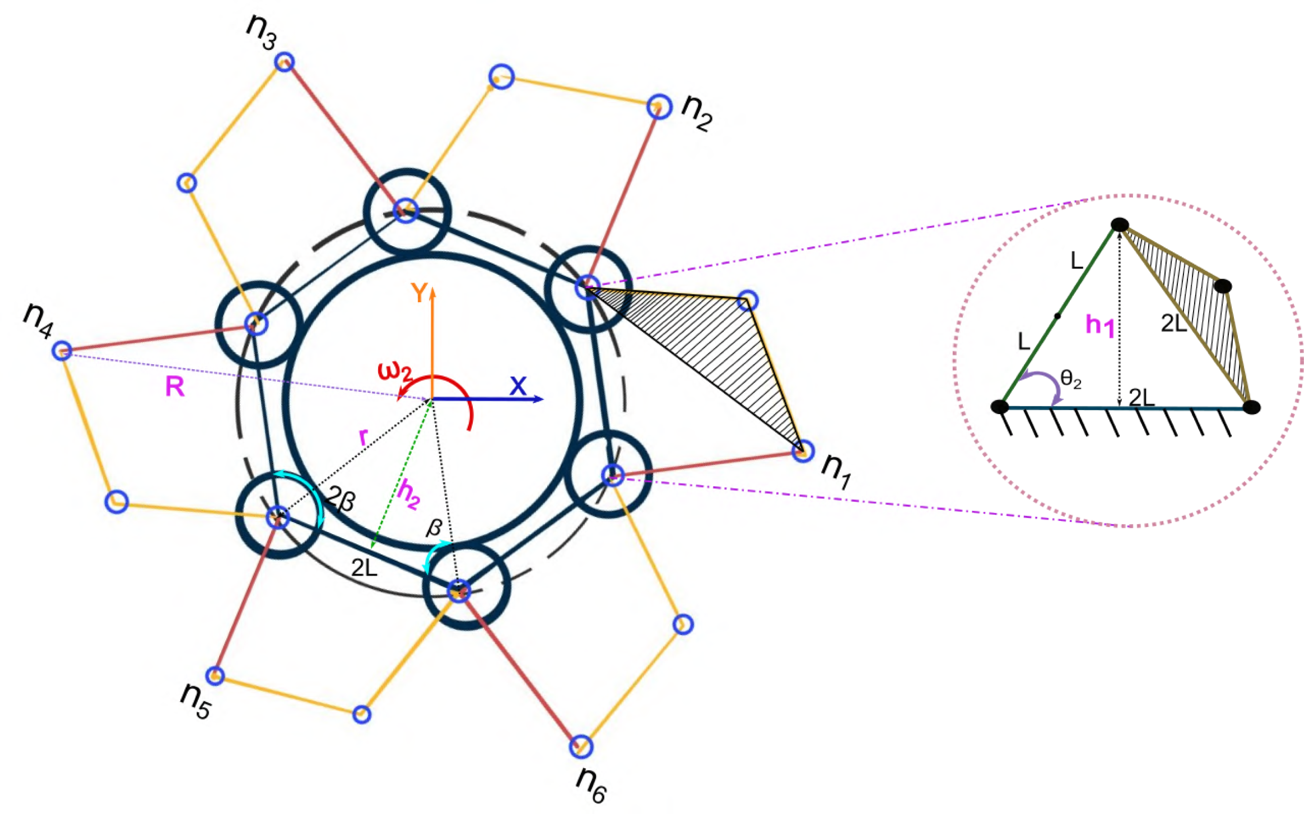
Figure 1. Conceptual proposal of the reconfigurable wheel.
During the expansion of the mechanism, the new effective radius is given by $R_{i} = h_{1}+h_{2}$
, where
$R_{i} = h_{1}+h_{2}$
, where $h_1$
represents the height of the mechanism expansion. When the mechanism is extended, an equilateral triangle is shaped with internal angles
$h_1$
represents the height of the mechanism expansion. When the mechanism is extended, an equilateral triangle is shaped with internal angles $\theta =60^\circ$
, (1), as indicated in the close-up of Fig. 1.
$\theta =60^\circ$
, (1), as indicated in the close-up of Fig. 1.
 \begin{equation} h_{1}=2L\;sin(\theta _{2}) \end{equation}
The length $h_2$
can be calculated based on the internal angle of the polygon, (2).
$h_2$
can be calculated based on the internal angle of the polygon, (2).
 \begin{equation} h_{2}=r\;sin(\beta ) \end{equation}
The reconfiguration radius (3) is given by the relationship between $R$
and
$R$
and $R_i$
, where
$R_i$
, where $R_i$
corresponds to the current configuration radius.
$R_i$
corresponds to the current configuration radius.
 \begin{equation} \Delta = \frac{R_{i}}{r} \end{equation}
To define the influence of the number of retractable mechanisms in the reconfiguration radius ratio, we propose a reconfiguration index as a function of the number of polygon sides. The internal angle of a regular polygon can be computed taking into account the number of sides $n$
as shown in (4).
$n$
as shown in (4).
 \begin{equation} \beta =90\frac{(n-2)}{n} \end{equation}
By substituting (4) in (2), we can obtain (5).
 \begin{equation} h_{2}=r\;sin \!\left (90\frac{(n-2)}{n}\right ) \end{equation}
To calculate $\Delta (n)$
based on the number of the polygon sides (6), we substitute (1) and (5) in (3).
$\Delta (n)$
based on the number of the polygon sides (6), we substitute (1) and (5) in (3).
 \begin{equation} \Delta (n) =\frac{2L\;sin\!\left ( \theta _2 \right ) + r\;sin \!\left ( 90\frac{\left ( n-2 \right )}{n} \right )}{r} \end{equation}
The length of the retractable mechanism $L$
(shown in Fig. 1) depends on the geometric parameters of the polygon and can be calculated as
$L$
(shown in Fig. 1) depends on the geometric parameters of the polygon and can be calculated as $L=rcos(\beta )$
.
$L=rcos(\beta )$
.
By substituting $L$
in 6 and factorising
$L$
in 6 and factorising $r$
, we can obtain (7). We rename
$r$
, we can obtain (7). We rename $\Delta (n)$
as
$\Delta (n)$
as $\phi$
, were
$\phi$
, were $\phi$
is the reconfiguration index.
$\phi$
is the reconfiguration index.
 \begin{equation} \phi =2cos \!\left (90\frac{(n-2)}{n}\right )sin(\theta _2)+ sin \!\left (90\frac{(n-2)}{n}\right ) \end{equation}
Equation 7 was evaluated numerically based on the number of retractable mechanisms (between 3 and 100) and the configuration of the retractable mechanism at the maximum extension ( $\theta _{2}=60^\circ$
). As can be seen in Fig. 2, there is a decrease in the reconfiguration radius as the sides of the circumscribed polygon increase. Three sides perform a reconfiguration index of
$\theta _{2}=60^\circ$
). As can be seen in Fig. 2, there is a decrease in the reconfiguration radius as the sides of the circumscribed polygon increase. Three sides perform a reconfiguration index of $2$
, while six mechanisms achieve a reconfiguration index of
$2$
, while six mechanisms achieve a reconfiguration index of $1.73$
.
$1.73$
.

Figure 2. Numerical evaluation of the reconfiguration index equation.
3. Kinematic and reconfigurable wheel design
This section describes the design of a reconfigurable wheel, taking into account the index reconfiguration reported above and the support points. The average reconfiguration ratio of the investigations reported is 1.5. Taking all these points into account, we have proposed a reconfigurable wheel with a diameter composed of SIX retractable mechanisms, theoretically giving a reconfiguration ratio of 1.73 with six support points.
Figure 3 shows the reconfigurable wheel in size, consisting of six retractable paddles based on symmetrically distributed 4-bar deltoid mechanisms. The Figure shows the kinematic diagram of the i-th retractable paddle.

Figure 3. Design of a reconfigurable wheel based on a 4-bar mechanism and kinematic diagram of the i-th retractable paddle.
The kinematics of the mechanism is derived from the kinematic diagram presented in the close-up of Fig. 3.
 \begin{equation} e=\sqrt{s_{1}^{2}+L_{1}^{2}-2s_{1}L_{1}cos(\theta _{2})} \end{equation}
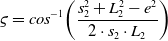 \begin{equation} \varsigma = cos^{-1}\!\left ( \frac{s_{2}^{2}+L_{2}^{2}-e^{2}}{2\cdot s_{2}\cdot L_{2}} \right ) \end{equation}
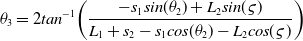 \begin{equation} \theta _3 = 2tan^{-1}\!\left ( \frac{-s_{1}sin(\theta _2)+L_{2}sin(\varsigma )}{L_{1}+s_{2}-s_{1}cos(\theta _2)-L_{2}cos(\varsigma )} \right ) \end{equation}
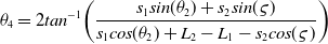 \begin{equation} \theta _4 = 2tan^{-1}\!\left ( \frac{s_{1}sin(\theta _2)+s_{2}sin(\varsigma )}{s_{1}cos(\theta _2)+L_{2}-L_{1}-s_{2}cos(\varsigma )} \right ) \end{equation}
The vector method of relative velocities is used for velocity analysis. The input in this case is the angular velocity of the link $s_1$
, and then for point
$s_1$
, and then for point $A$
, we have:
$A$
, we have:
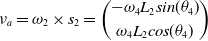 \begin{equation} \nu _{a} = \omega _{2}\times s_{2} = \binom{-\omega _{4}L_{2}sin(\theta _{4})}{\omega _{4}L_{2}cos(\theta _{4})} \end{equation}
The velocity of point $B$
with respect to link
$B$
with respect to link $L_2$
is defined by the Eq. (13).
$L_2$
is defined by the Eq. (13).
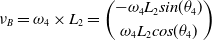 \begin{equation} \nu _B=\omega _{4}\times L_{2}=\binom{-\omega _{4}L_{2}sin(\theta _{4})}{\omega _{4}L_{2}cos(\theta _{4})} \end{equation}
On the other hand, the velocity of point $B$
with respect to link
$B$
with respect to link $s_2$
is defined by Eq. (14).
$s_2$
is defined by Eq. (14).
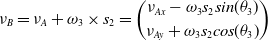 \begin{equation} \nu _B = \nu _A + \omega _{3}\times s_{2} = \binom{ \nu _{Ax}-\omega _{3}s_{2}sin(\theta _{3})}{ \nu _{Ay}+\omega _{3}s_{2}cos(\theta _{3})} \end{equation}
Equating (13) and (14), we have Equation in matrix form.
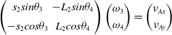 \begin{equation} \begin{pmatrix} s_{2}sin\theta _{3} & -L_{2}sin\theta _{4}\\[5pt] -s_{2}cos\theta _{3} & L_{2}cos\theta _{4} \end{pmatrix} \binom{\omega _{3}}{\omega _{4}} =\binom{\nu _{Ax}}{\nu _{Ay}} \end{equation}
Cramer’s rule gives the values for $\omega _3$
as described in Eq. (16) and for
$\omega _3$
as described in Eq. (16) and for $\omega _4$
as described in Eq. (17).
$\omega _4$
as described in Eq. (17).
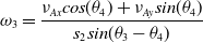 \begin{equation} \omega _{3} =\frac{\nu _{Ax}cos(\theta _4) + \nu _{Ay}sin(\theta _4)}{s_{2}sin(\theta _3-\theta _4)} \end{equation}
 \begin{equation} \omega _{4} =\frac{\nu _{Ax}cos(\theta _3) + \nu _{Ay}sin(\theta _3)}{L_{2}sin(\theta _3-\theta _4)} \end{equation}
The kinematic equations were solved numerically in the range $\theta = 0^\circ \cdots 60^\circ$
. The geometric parameters are defined as
$\theta = 0^\circ \cdots 60^\circ$
. The geometric parameters are defined as $s_{1} = s_{2} = 26.5 \,{\rm mm}$
,
$s_{1} = s_{2} = 26.5 \,{\rm mm}$
, $L_{1} = L_{2} = 53 \,{\rm mm}$
. Figure 4 illustrates the wheel reconfiguration process in four distinct positions using CAD software.
$L_{1} = L_{2} = 53 \,{\rm mm}$
. Figure 4 illustrates the wheel reconfiguration process in four distinct positions using CAD software.

Figure 4. Wheel reconfiguration process.
los puntos $A$
y
$A$
y $B$
.
$B$
.
The mechanism of the $i-th$
retractable paddle was constructed and simulated using GeoGebra, and kinematics equations in position and velocity were numerically evaluated. Figure 5 illustrates the reconfiguration process of the retractable paddle for
$i-th$
retractable paddle was constructed and simulated using GeoGebra, and kinematics equations in position and velocity were numerically evaluated. Figure 5 illustrates the reconfiguration process of the retractable paddle for $\theta =10^\circ$
,
$\theta =10^\circ$
, $20^\circ$
,
$20^\circ$
, $30^\circ$
,
$30^\circ$
, $40^\circ$
,
$40^\circ$
, $50^\circ$
y
$50^\circ$
y $60^\circ$
, along with the trajectory followed by points
$60^\circ$
, along with the trajectory followed by points $A$
and
$A$
and $B$
. The simulations demonstrate that the
$B$
. The simulations demonstrate that the $i-th$
paddle’s wheel can attain various reconfiguration points associated with the variable
$i-th$
paddle’s wheel can attain various reconfiguration points associated with the variable $\theta _{2}$
.
$\theta _{2}$
.

Figure 5. Numerical evaluation of the kinematic model of a retractable paddle of the reconfigurable wheel.
4. Robot transformation process
A two-wheeled robot was designed and manufactured to evaluate the transformation process of the robot.
Figure 6 shows the general description of the robot, which consists of a chassis, two reconfigurable wheels, a stabilisation tail and a microcontroller. The reconfigurable of each wheel is driven by an independent motor, while the movement of the robot is achieved by the control of two independent Dyanimexel AX-12 motors. The initiation of the reconfiguration is executed in response to an external signal transmitted via Bluetooth.
Figure 6. Description of the reconfigurable two-wheeled robot.
Both the wheels and the robot were manufactured by 3D printing technique using polylactic acid as the material. The reconfigurable radius of the constructed wheels was experimentally evaluated with the help of the “Tracker” software, a free video modelling and analysis tool based on the open-source Java Physics Framework.
The analysis involved placing a circular object at the tip of one of the retractable paddles, and using “Tracker,” this object was detected to calculate its position based on the variation of the entry angle.
Figure 7 shows the wheel during the reconfigurable process. Using the data obtained from image analysis, the kinematic model is evaluated for a range of the input angle $\theta _2$
movement from
$\theta _2$
movement from $0^\circ$
to
$0^\circ$
to $55^\circ$
. The retractable paddle is not brought to its limit position (
$55^\circ$
. The retractable paddle is not brought to its limit position ( $\theta _{2} = 55^\circ$
) in order to prevent a singularity in the mechanism. The idle wheel has a diameter of
$\theta _{2} = 55^\circ$
) in order to prevent a singularity in the mechanism. The idle wheel has a diameter of $100$
mm. From the graph, it is evident that the position of the mechanism tip along the Y-axis is
$100$
mm. From the graph, it is evident that the position of the mechanism tip along the Y-axis is $62.89 \,{\rm mm}$
indicating that the wheel expands by nearly
$62.89 \,{\rm mm}$
indicating that the wheel expands by nearly $63\%$
, This is slightly less than the expected
$63\%$
, This is slightly less than the expected $73\%$
, reconfiguration, as presented in Figure 7 for a robot with 6 retractable paddles.
$73\%$
, reconfiguration, as presented in Figure 7 for a robot with 6 retractable paddles.
Figure 7. Experimental validation of the reconfiguration of the wheel.
On the other hand, the transformation process of the wheel is active, with all 6 extremities unfolding simultaneously as the gears on each extremity rotate on each main gear. Figure 8 depicts the force analysis of the wheel transformation process. Figure A) shows the wheel in contact with the obstacle, where R is the radius of the disc, $F_{1x}$
and
$F_{1x}$
and $F_{1y}$
represent the forces exerted by the surface and
$F_{1y}$
represent the forces exerted by the surface and $F_{2x}$
and
$F_{2x}$
and $F_{2y}$
the forces exerted by the obstacle, m is the mass of the wheel. The power ratio can be expressed as:
$F_{2y}$
the forces exerted by the obstacle, m is the mass of the wheel. The power ratio can be expressed as:
 \begin{gather} F_{1x} - F_{2x} = ma_{x} \nonumber \\[5pt] F_{1y} + F_{2y}-mg = ma_{y}\nonumber \\[5pt] T_{R} = F_{2y} r\!\left ( 1- cos\!\left (\theta _{R} \right )\right ) - F_{2x} r\;sin \!\left (\theta _{R} \right ) \end{gather}
When the wheel rotates at a constant speed, the accelerations $a_x$
and
$a_x$
and $a_y$
are zero. As a result, the torque can be expressed as shown in Equation: 19:
$a_y$
are zero. As a result, the torque can be expressed as shown in Equation: 19:
 \begin{equation} T_{R}=\frac{\mu mg}{1+\mu ^{2}} \!\left ( \mu \!\left ( 1-cos\!\left ( \theta _{R} \right ) \right ) - sin\!\left ( \theta _{R} \right ) \right ) \end{equation}
Figure 8. Free body diagram in the process of scaling an obstacle, in the limit position.
On the other hand, the robot’s ability to overcome barriers is restricted to a specific range, dictated by the geometric elements of the reconfiguration mechanism. Figure 8(B) shows a free body diagram of the robot in its maximum position for overcoming an obstacle. This process assumes that the robot components are rigid. $d_1$
and
$d_1$
and $d_2$
denote the distances from the centre of the wheel to the tip of the rear bracket.
$d_2$
denote the distances from the centre of the wheel to the tip of the rear bracket. $n_1$
and
$n_1$
and $n_2$
denote the normal forces at support points
$n_2$
denote the normal forces at support points $p_1$
and
$p_1$
and $p_2$
, respectively, while
$p_2$
, respectively, while $f_1$
and
$f_1$
and $f_2$
represent the frictional forces at these points. These frictional forces act in the opposite direction of displacement.
$f_2$
represent the frictional forces at these points. These frictional forces act in the opposite direction of displacement.
In Figure(B), the robot is depicted in the process of leaving the surface. The height of the obstacle is determined by the robot’s obstacle limit height. the torque at the centre of the wheel is given by the equation:
 \begin{align} M & = N_{2}d_{2}cos\!\left ( \theta _{R} \right ) cos\!\left ( \lambda \right ) + N_{2}d_{2}sin\!\left ( \theta _{R} \right ) sin\!\left ( \lambda \right ) - N_{1}d_{1} cos \!\left ( \delta \right ) \nonumber \\[5pt] &= N_{2}d_{2}cos\!\left ( \theta _{R} - \lambda \right ) - N_{1}d_{1} cos \!\left ( \delta \right ) \end{align}
where $\Omega$
denotes the angle between
$\Omega$
denotes the angle between $N_2$
and the vertical direction,
$N_2$
and the vertical direction, $\delta$
denotes the angle between
$\delta$
denotes the angle between $L_1$
and the horizontal direction, and
$L_1$
and the horizontal direction, and $\lambda _1$
and
$\lambda _1$
and $\lambda _2$
denote the angles between
$\lambda _2$
denote the angles between $L_2$
on different retractable vanes and the horizontal direction.
$L_2$
on different retractable vanes and the horizontal direction. $H_R$
is the reconfigurable height from disc centre to retractable blade tip, while
$H_R$
is the reconfigurable height from disc centre to retractable blade tip, while $H_O$
is the obstacle height. The height of the obstacle to be surmounted can be determined by the following calculation:
$H_O$
is the obstacle height. The height of the obstacle to be surmounted can be determined by the following calculation:
 \begin{equation} H_{O} = H_{R} \!\left ( sin \!\left ( \lambda _{1} \right ) + sin\!\left ( \lambda _{2} \right )\right ) \end{equation}
Figure 9 illustrates the process of the robot moving and climbing an obstacle while simultaneously reconfiguring its wheels. Figure 9(A) displays the robot’s displacement with closed limbs. Figure 9(B) depicts the robots wheels in a configuration that touches the obstacle. Figure 9(C) depicts the robot making contact with the upper surface of the obstacle using one limb and touching the traversing surface with its tail. Figures 9(D) and (E) illustrate the robot ascending the obstacle, and Figure 9(F) displays the robot with the adaptable wheel in a compact arrangement, traversing over the obstacle’s summit.

Figure 9. Sequence of robot movement and reconfiguration of its wheels.
The robot’s torque was numerically assessed by applying Eq. (20) with data obtained from the virtual CAD model in SolidWorks software. Fig. 10(a) illustrates the correlation between the reconfiguration angle ( $\theta _2$
) and its corresponding torque during a static reconfiguration process. On the other hand, Fig. 10(b) illustrates the torque calculation for the wheel, corresponding to the displacement process outlined in Fig. 9.
$\theta _2$
) and its corresponding torque during a static reconfiguration process. On the other hand, Fig. 10(b) illustrates the torque calculation for the wheel, corresponding to the displacement process outlined in Fig. 9.
Figure 10. Torque profile of the reconfigurable wheel using Eq. (20).
5. Experimental results
This section details the experimental evaluation of the mobile robot with reconfigurable wheels under various conditions, maintaining a constant angular velocity of $3.5 \,{\rm rad/s}$
over a period of 10 s.
$3.5 \,{\rm rad/s}$
over a period of 10 s.
The performance of the robot was evaluated by means of computer vision. Figure 11 illustrates a diagram of the experiment. The camera DS UI-3240 CP-HQ 1/ 1.8′′, with a resolution of 1280 $\times$
1024 ppi at 60 fps was located in a fixed position to record videos of the displacement and reconfiguration of the robot during obstacles overcoming as shown in Fig. 11.
$\times$
1024 ppi at 60 fps was located in a fixed position to record videos of the displacement and reconfiguration of the robot during obstacles overcoming as shown in Fig. 11.
The system parameters were experimentally estimated by analysing video frames of the transformation process. This was accomplished using Zhang’s well-established method for camera calibration, employing a 2D checkerboard.
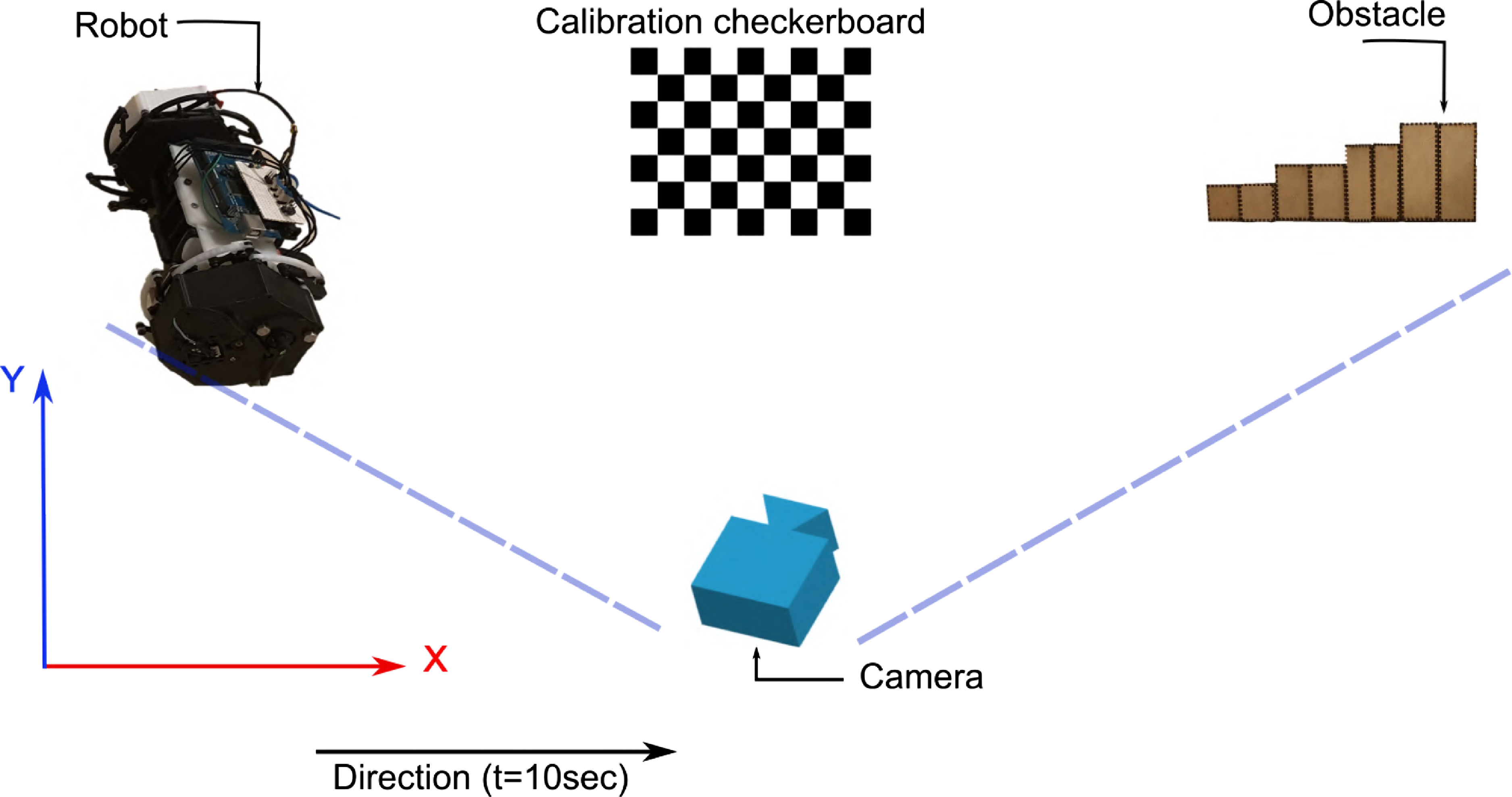
Figure 11. Diagram of the experiment setup.
Furthermore, the robot’s ability to overcome obstacles of various heights (50 mm, 75 mm, 100 mm, and 125 mm) was evaluated based on the success rate. Figure 12 shows a scheme of the robot and the obstacles, also in this figure is illustrated a zoom of the four-bar linkage reconfigurable wheel, where two motors are used, one for the transformation process and the other one for the displacement.
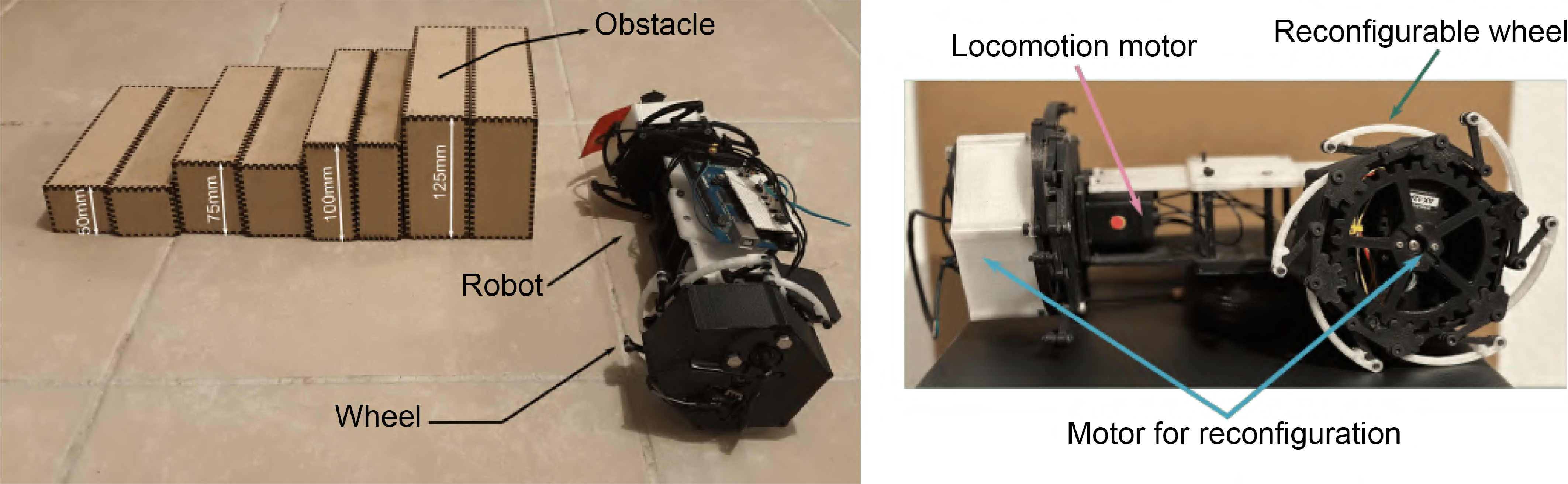
Figure 12. Scheme of the robot and the obstacles.
The kinematics shown early ensure that the whole wheel configurations are reachable during the reconfiguration process. Additionally, to guarantee motion constrains in the wheels, the motors used in the reconfiguration process were blocked after the reconfiguration.
A total of 50 attempts were made to overcome obstacles with heights of 50, 75, 100, and 125 mm, as illustrated in Fig. 12.
Figure 13 shows a sequence of images of the robot overcoming a 50 mm obstacle. Note that the intentional gap between both obstacles serves the purpose of ensuring the stabilisation of the tail during movement and the reconfiguration process. This design choice aims to prevent failures during obstacle crossing.
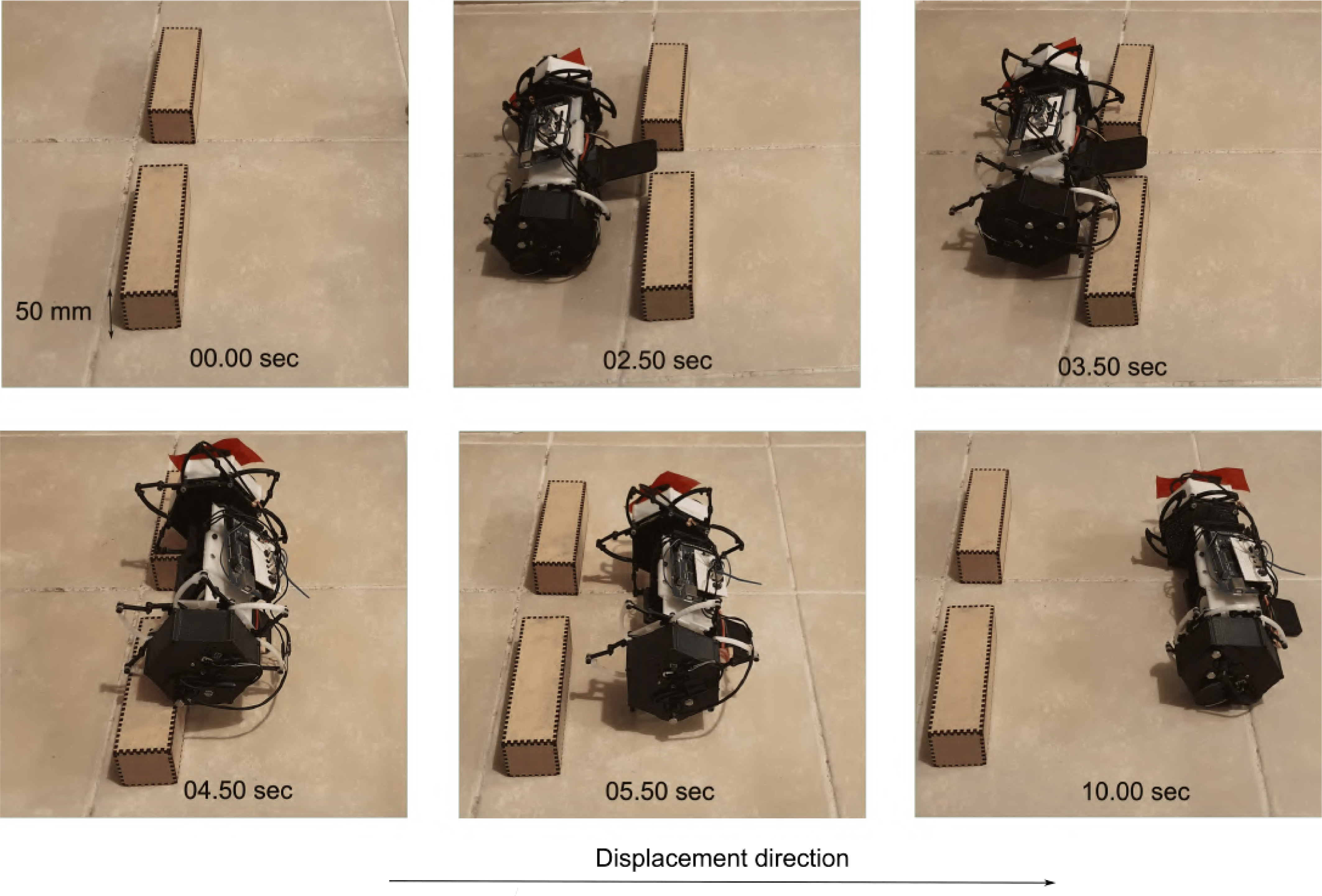
Figure 13. Overcoming a 50 mm high obstacle.
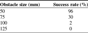
Table I shows the success rate of the robot in overcoming obstacles. The robot successfully cleared the 50 mm obstacle in 48 out of 50 attempts, while for the 75 mm, obstacle it cleared 15 out of 50 attempts. The 100 mm obstacle proved to be a challenge, with the robot only succeeding in 1 out of 50 attempts, and it failed to clear the 125 mm obstacle in any of the attempts.
Table I Percentage of success in overcoming various obstacles.
Based on the experimental validation of the reconfiguration ratio, the wheel demonstrates the capability to expand by $62.89\%$
, as illustrated in Fig. 7. This substantial expansion is a primary factor preventing the robot from successfully overcoming obstacles of
$62.89\%$
, as illustrated in Fig. 7. This substantial expansion is a primary factor preventing the robot from successfully overcoming obstacles of $125\, {\rm mm}$
. However, in the case of obstacles measuring
$125\, {\rm mm}$
. However, in the case of obstacles measuring $100\,{\rm mm}$
, the robot manages to overcome them, mainly due to the reconfiguration ratio and the fact that the mechanisms were prototyped in plastic, which lacks the required rigidity.
$100\,{\rm mm}$
, the robot manages to overcome them, mainly due to the reconfiguration ratio and the fact that the mechanisms were prototyped in plastic, which lacks the required rigidity.
Additionally, the energy consumption of the robot when overcoming obstacles was assessed. Energy consumption was measured through current sensing of the motors during the 10-s wheel reconfiguration process that the robot underwent while overcoming obstacles. The Fig. 14 shows that as the obstacle gets higher (100 mm obstacle), the power to overcome it increases. The 125 mm obstacle was discriminated because the robot was not able to overcome it. The current measurements were normalised.
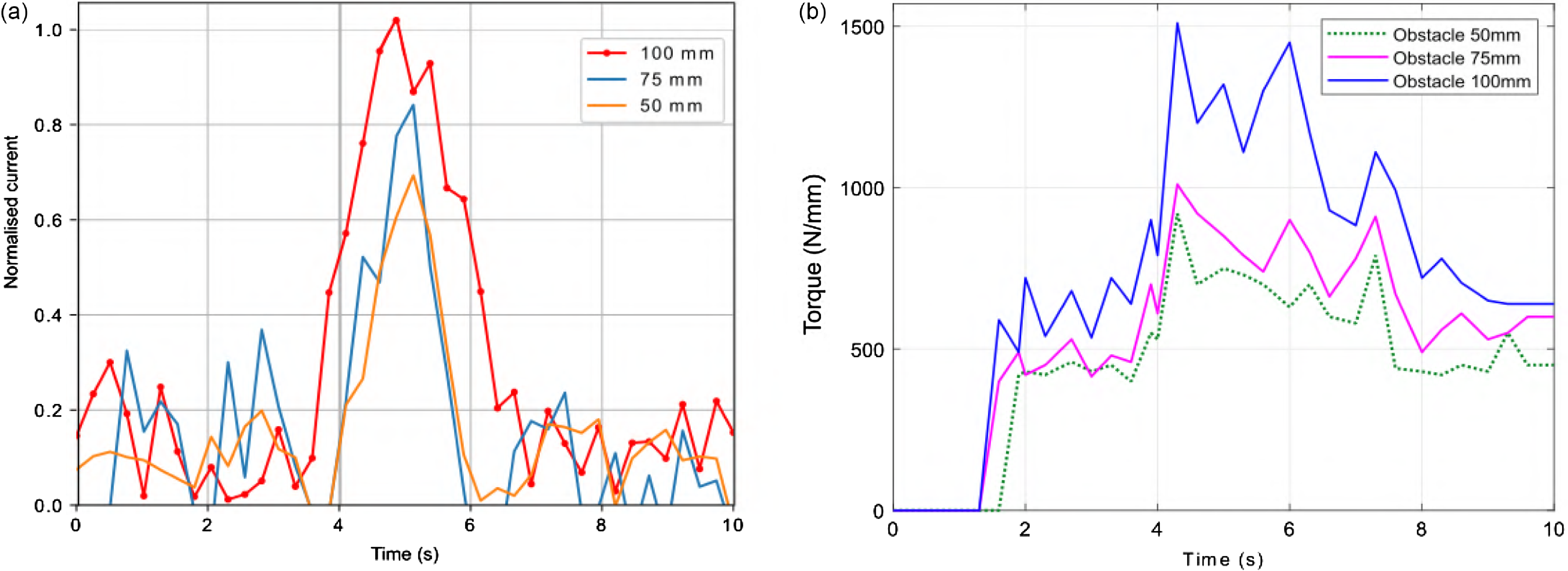
Figure 14. Energy consumption and torque calculation during the process of reconfiguring wheels.
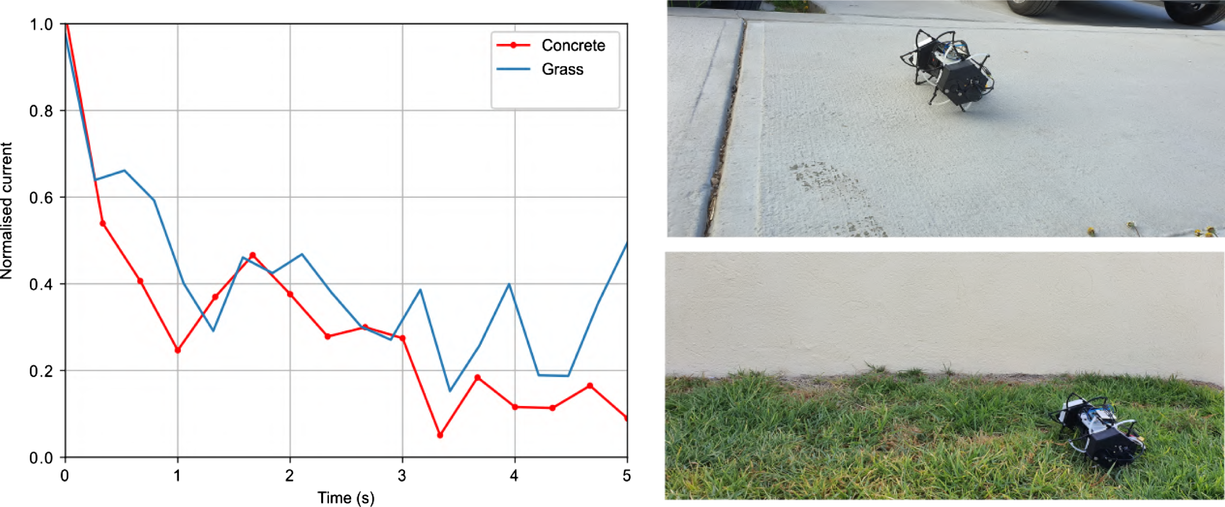
Figure 15. Energy consumption during displacement in different terrains.
On the other hand, we assessed the robot’s performance in terms of energy consumption while navigating two distinct terrains: grass and concrete. Navigating through grass proved to be more challenging, leading to higher energy consumption by the robot, considering the full-reconfigured wheels during the displacement as shown in Fig. 15.
6. Conclusion
This paper has presented a comprehensive exploration of the design, kinematic analysis, and experimental validation of a Four-bar linkage reconfigurable robotic Wheel for adaptive size modification. In addition, the authors introduce a reconfiguration index based on the number of retractable mechanisms, emphasising the relationship between the effective radius during expansion and the polygonal configuration.
The robot systems mentioned in the introduction section incorporate some variants of the four-bar mechanisms, in which gears or bars may be used to perform the expansion. In most of the articles reviewed, the way in which they perform the transformation is conditioned by the system’s contact with an obstacle. In contrast, the system proposed in this article incorporates the use of two motors for each wheel, aiming to provide terrain-independent transformation. This feature provides an advantage over other systems that rely solely on the terrain in which they operate. Also, the reconfigurable wheel system includes six retractable paddles. When in their fully transformed state, this design allows for a smooth ride and enhanced surface adherence.
The experimental results have provided valuable insights into the wheel’s capabilities and limitations, particularly in overcoming obstacles of varying heights.
The kinematic analysis laid the foundation for ensuring reachability during the reconfiguration process. The experimental trials revealed notable achievements in overcoming obstacles, with a high success rate for the 50 mm obstacle and insightful observations regarding the challenges posed by obstacles of greater heights. The wheel’s versatility is demonstrated by its excellent reconfiguration ratio of 62.89%, which exhibits its capacity to expand and navigate obstacles as large as 100 mm.
Furthermore, the assessment of energy consumption during obstacle overcoming and terrain navigation provided critical data for understanding the robot’s performance under different conditions. The correlation between obstacle height and power consumption, as well as the varying energy demands on different terrains, adds depth to our understanding of the practical implications of the reconfigurable wheel’s design.
The experiments demonstrate that the torque also varies according to the size of the obstacles, and the 100, $75$
, and
$75$
, and $50$
mm require a maximum torque of
$50$
mm require a maximum torque of $1500$
,
$1500$
, $1010$
, and
$1010$
, and $910$
N/mm, respectively.
$910$
N/mm, respectively.
The experiments demonstrate that torque varies proportionally with the size of obstacles, with the 100 mm, 75 mm, and 50 mm obstacles requiring maximum torques of $1500$
,
$1500$
, $1010$
, and
$1010$
, and $910$
N/mm, respectively.
$910$
N/mm, respectively.
Despite the challenges encountered in overcoming the 125 mm obstacle, the overall findings suggest promising applications for the four-bar linkage reconfigurable robotic wheel in scenarios where adaptive size modification is crucial. Future research could focus on refining the design for enhanced rigidity and exploring potential improvements to overcome higher obstacles.
These findings present an encouraging outlook for ongoing enhancements in mobile robot mobility. They indicate that the development of reconfigurable wheels represents an innovative and promising path in the evolution of applied robotics.
Author contributions
X. Yamile Sandoval Castro and Sergio Muñoz-Gonzalez developed the concept and prototype of the reconfigurable mobile robot and experimentation, as well as contributed to the writing of the paper. Mario A. Garcia-Murillo contributed to kinematic analysis reconfiguration study as well as contributed to the writing of the paper.
Financial support
This research received no specific grant from any funding agency, commercial, or not-for-profit sectors.
Competing interests
The authors declare no competing interests exist.
Ethical standards
Not applicable under the heading.


