


1. Introduction
With the rapid development of robots and artificial intelligence technology, the world is developing into a world where humans and robots coexist due to advanced human-robot interaction. As a result, cleaning robots, drones, guide robots, delivery robots, and service robots have already penetrated and are used in various industries. Advances in robotics have enabled our machines to explore the sea, go to Mars, and perform surgery. Robots are getting more precise, innovative, functional, and better. In particular, the research and development(R&D) on humanoid robots that are similar in appearance to humans, which are the most suitable form for human living environments, is being actively conducted. Humanoid robots have the advantage of being able to adapt to the environment formed by humans and are available to move in uncertain environments in various ways, such as walking, climbing stairs, manipulating tasks, collaborating with humans, and running. It is natural to conclude that humanoid robots are a fascinating topic for the future environment.
WABOT, developed by a research team at Waseda University in Japan, and ASIMO from Honda have led the development of humanoid robots with remarkable bipedal locomotion, leading to Hubo, who won the Darpa Robotics Challenge, and Atlas, developed by Boston Dynamics (Kato, Reference Kato1973; Kato et al., Reference Kato, Kato, Ohteru, Shirai, Matsushima, Narita, Sugano, Kobayashi and Fujisawa1987; Sakagami et al., Reference Sakagami, Watanabe, Aoyama, Matsunaga, Higaki and Fujimura2002; Jung et al., Reference Jung, Jung, Lim, Bae, Lee, Joe and Oh2018). Also, to develop a humanoid robot with a structure more similar to that of a human, Kengoro at the University of Tokyo, which has a musculoskeletal structure identical to the human body, is being studied (Asano et al., Reference Asano, Kozuki, Ookubo, Kawamura, Nakashima, Katayama, Yanokura, Hirose, Kawaharazuka, Makino, Kakiuchi, Okada and Inaba2016). In addition, as research on the convergence of artificial intelligence and robots is active, research on applying artificial intelligence to humanoid robots is increasing. Saeed et al. solved the balance problem when a humanoid robot drags heavy objects through deep reinforcement learning (Saeedvand et al., Reference Saeedvand, Mandala and Baltes2021), and Rodriguezel al. successfully applied a learned model to the real robot in simulating with DDPG (Deep Deterministic Policy Gradient), a reinforcement learning algorithm, to create a human-like walking pattern (Rodriguez & Behnke, Reference Rodriguez and Behnke2021).
International robot competitions have significantly gained attention among robotics researchers and are essential research benchmarks in robotics. International robot competitions that directly involve humanoid robots perform certain activities such as sports games and magic. The two most representative international robot tournaments that engage humanoid robots to play sports are FIRA RoboworldCup (soccer, archery, sprint, marathon, and weightlifting) (Baltes, Tu, et al., Reference Baltes, Tu, Sadeghnejad and Anderson2017) and RoboCup (Gerndt et al., Reference Gerndt, Gerndt, Seifert, Baltes, Sadeghnejad and Behnke2015). The competitions help guide research by having a clear road map that slowly increases the complexity and the difficulty of the challenges that teams must overcome. The RoboCup committee has reported in the robot soccer competition that the road map aims to beat the FIFA World Cup champion team in 2050 (Baltes, Sadeghnejad, et al., Reference Baltes, Sadeghnejad, Seifert and Behnke2014; Paetzel & Hofer, Reference Paetzel and Hofer2019). On the other hand, the FIRA organizing committee successfully organized the first robot-human archery competition in 2018 (Tu et al., Reference Lin, Li, Hung and Baltes2020). Tu et al. have implemented their robot’s design and shooting stance, which in this competition challenges a human archery player. The suggested posture consists of primitive arms’ motion for more torque on archery equipment (bow and string). However, the robot got second place in this competition and lost to a human player from Chung Kong Senior High School. This outcome shows that progress in humanoid robot research continues to grow in the present and the future. Another kind of humanoid robot competition launched in 2016 is the IEEE IROS Humanoid robot Application Challenge(HAC) (Moon et al., Reference Moon, Sun, Baltes and Kim2017; Baltes et al., Reference Baltes, Sun and Moon2018). With the central theme of magic and music, IROS-HAC aims to make the humanoid robots perform magic like human magicians and communicate with the audience. Magic tricks are performed in magic shows based on mathematical, scientific, and psychological principles. In particular, we should focus on optimizing complex technologies-based magic tricks for the robot magician to interact with the audience (Williams & McOwan, Reference Williams and McOwan2014). From the judgment viewpoint, the winner is decided by successful performance and scientific contribution applied to the robot. The robot with Human-Robot Interaction(HRI), a successful magic trick, and a positive scientific contribution are more likely to win (Jeong et al., Reference Jeong, Yang and Baltes2022).
In order to develop the various advanced functions of the humanoid robot described above in the real world, the production of a robot is unavoidable. When designing a humanoid robot, however, it is tempting to make use of the latest technology and expensive hardware (Radford et al., Reference Radford, Radford, Strawser, Hambuchen, Mehling, Verdeyen, Donnan, Holley, Sanchez, Nguyen, Bridgwater, Berka, Ambrose, Markee, Fraser-Chanpong, McQuin, Yamokoski, Hart, Guo, Parsons, Wightman, Dinh, Ames, Blakely, Edmondson, Sommers, Rea, Tobler, Bibby, Howard, Niu, Lee, Conover, Truong, Reed, Chesney, Platt, Johnson, Fok, Paine, Sentis, Cousineau, Sinnet, Lack, Powell, Morris and Akinyode2015). However, if left unchecked, this desire can lead to a ballooning of the manufacture and hardware cost. Furthermore, the best hardware performance-wise might not be the best fit for a specific robot design, which also has to consider elements such as mass distribution and power consumption (Kaneko et al., Reference Kaneko, Kaneko, Kanehiro, Morisawa, Akachi, Miyamori, Hayashi and Kanehira2011). This work presents a lightweight humanoid robot platform called Robinion Sr (see figure 1). It is a 135 $cm$
tall humanoid robot and weighs approximately 12
$cm$
tall humanoid robot and weighs approximately 12 $kg$
. We describe our hardware and software systems with the target of developing a low-cost and robust humanoid robot. Notably, our robot’s main computer is a low-cost Tablet computer without GPU. Nonetheless, we are still able to deploy state-of-the-art deep learning systems such as a modified tiny YOLO-V3 model. We circumvent the need for a dedicated GPU by making use of Google’s Coral USB accelerator, which can still achieve real-time inference speed by compiling the processed models into a particular format (Aguiar et al., Reference Aguiar, Dos Santos, De Sousa, Oliveira and Santos2020).
$kg$
. We describe our hardware and software systems with the target of developing a low-cost and robust humanoid robot. Notably, our robot’s main computer is a low-cost Tablet computer without GPU. Nonetheless, we are still able to deploy state-of-the-art deep learning systems such as a modified tiny YOLO-V3 model. We circumvent the need for a dedicated GPU by making use of Google’s Coral USB accelerator, which can still achieve real-time inference speed by compiling the processed models into a particular format (Aguiar et al., Reference Aguiar, Dos Santos, De Sousa, Oliveira and Santos2020).
In Section 2, we introduce the humanoid robot along with its mechanical structure, electrical structure. Section 3 describes a user-friendly graphical user interface(GUI)-based software. We explain our analytic inverse kinematics solver and trajectory generator in section 4. We show our custom version of a deep learning method using the tiny YOLO-V3 model in Section 5. We present the results of our work in Section 6. Finally, we present our conclusion and future paths of the research in Section 7.
Table 1. Specifications of different popular humanoid robot platforms

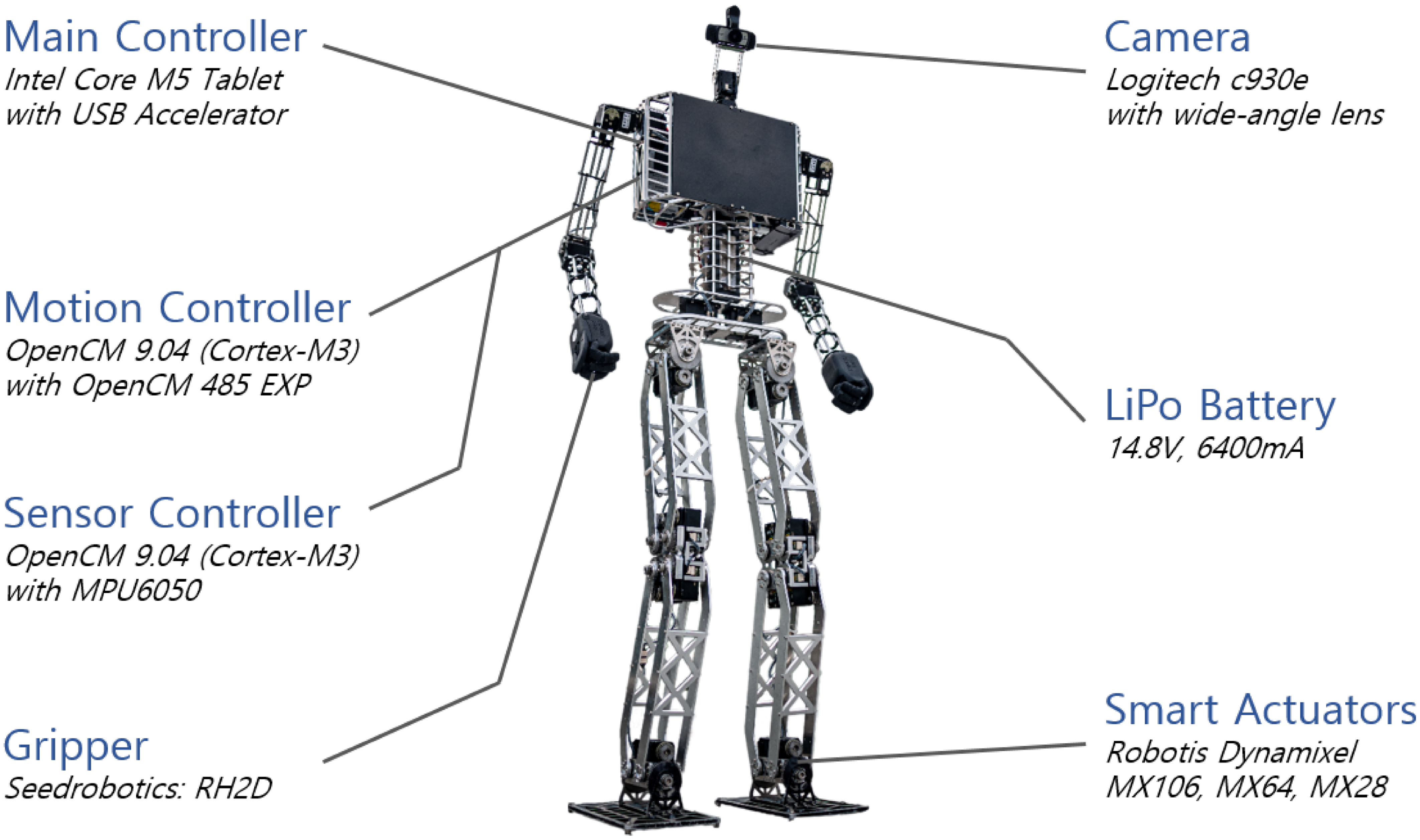
Figure 1. Robinio Sr. with electronic components.
2. Mechatronic design
Manufacturing a humanoid robot is high cost and time-consuming, so it is essential to clarify the purpose and expandability of the humanoid robot before manufacturing. Optimizing mechanics, electronics, and software to maximize the robot’s performance while minimizing the cost of manufacturing the robot is the target of this research. This section clarifies the mechanical structure, electrical structure, and GUI-based software related to the lightweight and durable humanoid robot. The development cost of our humanoid robot is lower than the commercially available small humanoid robot Darwin-OP3Footnote 1 of ROBOTIS.Footnote 2 It is manufactured at around one-third the price of NimbRo-OP2(X) from the University of Bonn, which is one of the lowest production costs for humanoid robots of similar size (Ficht et al., Reference Ficht, Ficht, Farazi, Rodriguez, Pavlichenko, Allgeuer, Brandenburger and Behnke2020). The following table 1 shows the details of the humanoid robot platforms and the specifications. The analysis compares the specifications of Robinion Sr. with those of Nimbro-OP2(X), a similar-sized humanoid robot, and Darwin-OP3, a commercial humanoid robot.
Compared to other humanoid robots of similar size, the Robinion Sr. has a high degree of freedom due to its gripper. Generally, humanoid robots have six joints on each of their legs, a standard structure. However, the parallel-kinematics design with no actuator in each knee reduced the total number of actuators in the humanoid robot leg. It allows the robot to be lighter as well as cost-effective. Robinion Sr. has a lower manufacturing price than the commercial robot Darwin-OP3 despite significantly improved mechanical and electrical structure. Manufacturing a high-performance humanoid robot such as Robinion Sr. would be advantageous in cost, maintenance, and scalability. Since Robinion2 was first developed in 2017, the mechatronic system and performance have been improved, which will be described in detail in Sections 2.1 and 2.2.
2.1. Mechanic design
As robust mechanical design significantly affects the movement of robots, robotic designers are required to consider many factors such as size, weight, frame, actuator, torque, gear, bearing, and cost. The reusability and scalability of the robot design are essential since humanoid robots are historically costly to manufacture. Robinion Sr. was first designed in 2017 and has improved its mechanical structure through continuous partial upgrades. Robinion Sr. was developed for robot gait research and intelligent robot competitions such as Robocup and FIRA, robust and lightweight leg design, and designed for high efficiency and a reasonable cost. Table 2 describes the mechanical specification of the lightweight humanoid robot.
Table 2. Robinion Sr. mechanical specifications
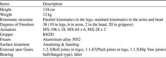
Robinion Sr. stands 134 cm tall and weighs approximately 12 kg. On a humanoid robot, the standard kinematic structure is for each leg to have six joints: roll and pitch joints in each ankle, pitch joint in each knee, and yaw, pitch, and roll joints in each hip. The parallel structure has five joints except for the knee joint on each leg. Our humanoid robot utilizes the parallel mechanism for the leg’s kinematic structure, which is lightweight and low in cost. The knee-less joint design controls the knee joint by calculating the ankle and hip joint movements. It has 38 degrees of freedom, with ten in each leg, six in each arm, two in the head, and twenty in the grippers, using 30 actuators. To increase torque, all of the roll and pitch joints of the legs use dual motors and external gears. Nevertheless, even the two actuators’ combined torque was insufficient, so we designed external spur gears to provide adequate torque (see figure 2).
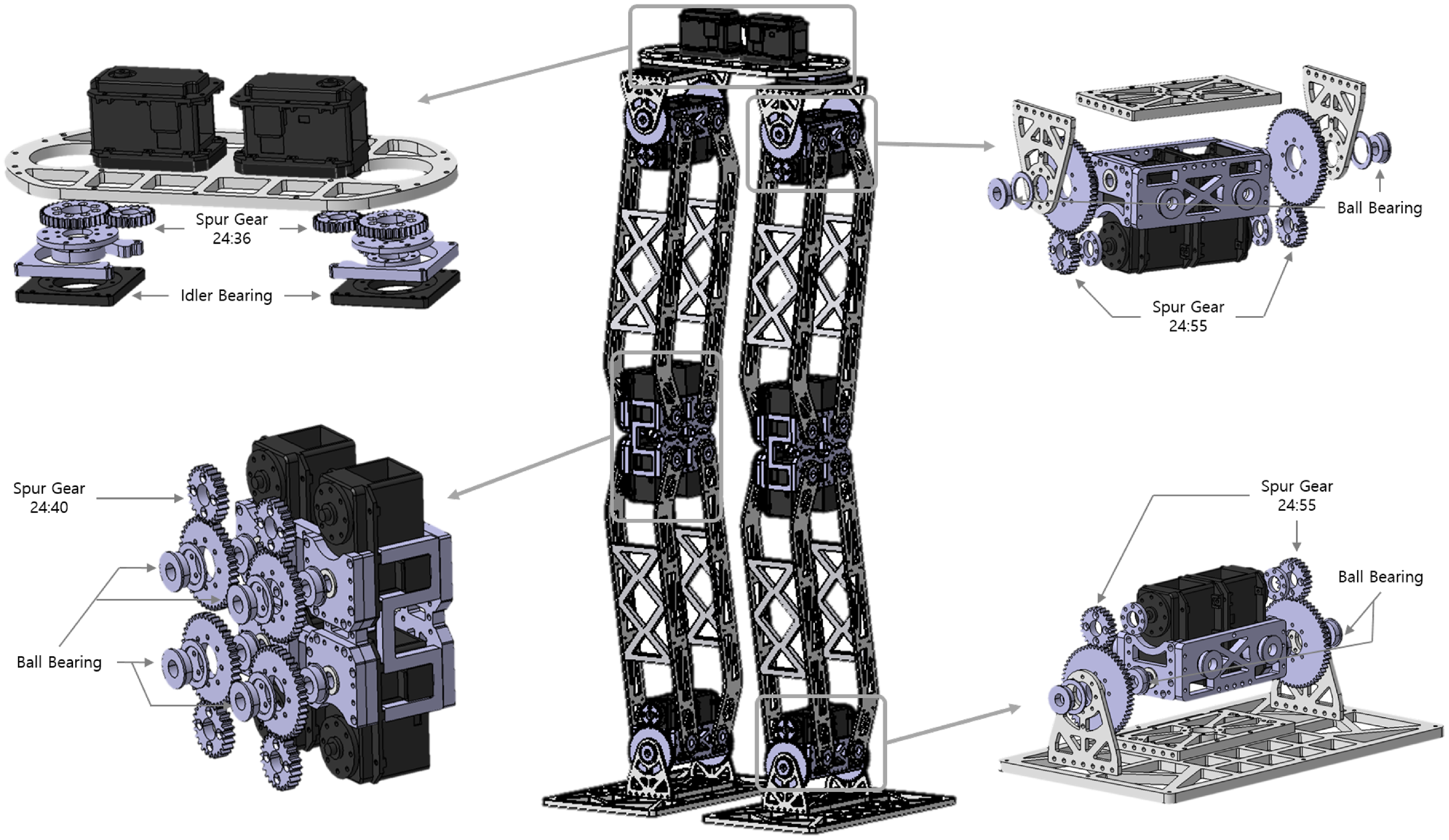
Figure 2. Mechanism design of legs with external gears.
The similar-sized robots use four actuators to control single-pitch joints in the legs: ankle and hip joints. To reduce the overall weight and cost, however, we designed dual actuators with external gears, which are standard spur gears, in all joints of the legs. Each joint has a gear ratio of 24:55 for the ankle and hip roll joints, 24:36 for the knee pitch joints, and 24:40 for the hip yaw joints. The selection of bearings is essential for precise control. In particular, the backlash of the hip yaw joint has a significant effect on walking gait. We stabilized the walking gait with idler bearings to reduce backlash for the hip yaw joint and realized smooth motions with flange-type ball bearings. In order to achieve high strength and be lightweight, the robot frame is constructed with sanded and anodized aluminum. Intelligent actuators Dynamixel MX seriesFootnote 3 from ROBOTIS are mounted onto the humanoid robot. There are eighteen MX-106Rs on the legs, six MX-64Rs on the arms, and two MX-28Rs on the head. A variety of advanced features are contained in the Dynamixel MX series, with precise position control through PID control, 360-degree positioning, speed control, and torque control via the current sensor. The humanoid robot has a detachable gripper, the RH2D,Footnote 4 which is an advanced gripper with force control.
2.2. Electronics
The Electrical component of the humanoid robot comprises three parts: the main controller that recognizes the environment and manages the behavior, the motion controller that calculates inverse kinematics, generates gait trajectory, and controls intelligent actuators, and the sensor controller that reads the IMU raw data and computes Euler angles. Table 3 presents the electrical specifications of the proposed humanoid robot, including the power source, controllers, and sensor.
A four-cell Lithium Polymer (LiPO) battery with a capacity of 6,400mA power the electronic system, which are the motion controller, sensor controller, and actuators. The electronic system has been optimized to allow up to one hour of battery life with motion control. A tablet PC with an Intel Core m5 processor, 4 GB of memory, and 128 GB SSD of storage serves as the main processing unit of the humanoid robot. This tablet PC, which is the main controller, contains a battery to extend the lifetime of the power source. Furthermore, the robot uses an inexpensive Coral USB acceleratorFootnote 5 with high-performance machine-learning inferencing capabilities. The accelerator detects objects using deep learning techniques, and it is available to replace expensive GPUs. Our software utilizes the accelerator to recognize a ball, goalposts, robots, and junctions for autonomous soccer. It uses an open-source robot controller called OpenCM 9.04,Footnote 6 embedded with an ARM Cortex-M3 microcontroller for its motion controller and sensor controller. OpenCM also supports the ROS embedded system and provides UART, SPI, and other functions. Various libraries can be efficiently accessed and programmed using the Arduino IDE. The motion controller includes an extension board, OpenCM 485 EXP,Footnote 7 for controlling Dynamixel adequately via RS485 and TTL connectors. The inverse kinematics solution and the generation of a trajectory of the walking gait are calculated in the 32-bit sub-controller to reduce the amount of computation carried out by the main controller. Since the motion controller is not designed for a 6-DoF standard structure of legs commonly needed for the numerical inverse kinematic analysis, we developed an analytical inverse kinematics solver for the 5-DoF parallel system of legs using trigonometric formulas. The sensor controller includes OpenCM and an MPU6050, which integrates three axes gyroscopes and three axes accelerometers. In order to have a sense of stability in the robot, the sensor controller reads six axes of IMU information and measures the raw data to calculate the Euler angles. The humanoid robot has been developed with a closed-loop stable walking gait based on the IMU. Robinion Sr. walks stably at speeds of up to 25 cm/s. Through USB connections, the main controller transmits inverse kinematics parameters to the motion controller and receives IMU data from the sensor controller. Figure 1 illustrates the location of each component, such as the controllers located in the body, the camera attached to the head, and the LiPo battery inside the body.
3. Software
The software and firmware are designed based on Robinion version 1 (Robinion v1), a previous humanoid robot platform with a similar mechanical structure and smaller size (Yang et al., Reference Yang, Jeong and Baltes2019). Not only is this system designed specifically for autonomous soccer, and it is also used for various research purposes, such as closed-loop omnidirectional walking, object detection with image processing and deep learning algorithms, and localization. An overview of the firmware and software architecture of the humanoid robot is shown in figure 3.
Table 3. Actuator and electronic specifications of Robinion Sr

Figure 3. System architecture of robinion Sr.
To reduce the amount of computation that each controller must do and to have an affordable electrical system, the humanoid robot is designed to use three independent controllers: the main controller, motion controller, and sensor controller. The main controller uses image processing and deep learning algorithms to recognize objects or environments. According to the recognized objects and environments, the robot behaves according to the state machine to perform the given task. The main controller transmits parameters of the pre-programmed motions to the motion controller to play the required actions in the FIRA Hurocup and HAC competitions and research. It is also possible to monitor data loggers, send inverse kinematics information to the motion controller, and control the humanoid robot via the joystick. The motion controller calculates inverse kinematics solutions for walking in real-time in order to generate gait trajectories. It contains a motion player, which behaves with pre-programmed motions for the competitions and manipulation tasks. The motion controller commands the position and velocity of every actuator in the head, arms, and legs. Intelligent humanoid robots need to recognize the values of their current orientation for balance. With the quaternion, the IMU uses a dedicated processor named DMP to determine the roll, pitch, and yaw angles.
Figure 4 presents a graphical user interface (GUI) developed with QtFootnote 8 and Python for users to control various robot functions efficiently. The GUI-based software includes categories for competitions such as FIRA Hurocup, Humanoid robot Application Challenge (HAC), Robocup humanoid league, and research. Game, image, and motion are on three separate pages in each category. On the Game page, it is possible to monitor the object recognition and behavior of the robot for each competition and research and to check the current robot orientation value calculated from the IMU sensor. There are buttons for testing robot motions such as omnidirectional walking, kicking, and head moving, and setting initial orientation values. It is possible to recognize objects through color recognition by dragging the mouse on the Image page. Color recognition uses the Lab color space, which is robust to light, to detect objects. In addition, slide bars allow users to change the range of L, a, and b to set a more precise detection. With the Motion page, users transmit the inverse kinematics parameters for walking to the humanoid robot in real-time, fine-tune it to find suitable values, and save and load the values. Additionally, the software contains features such as detecting objects using image processing algorithms and deep learning models, controlling the robot with a joystick, interacting with other robots for multi-robot cooperation, recognizing a voice, and speaking sentences with text-to-speech (TTS). It establishes serial communication between each controller and reads video frames from the camera.

Figure 4. View of our GUI-based software for robot control.
4. Gait analysis
One of the most crucial aspects of humanoid robots is the ability to walk with stability. Stable walking for robots requires complicated mathematical approaches such as kinematics, dynamics, zero moment point(ZMP), central pattern generator(CPG), and feedback control theories. Furthermore, the leg structure of most humanoid robots is generally designed with standard kinematics, which has six degrees of freedom: roll and pitch joints in the ankle, pitch joint in the knee, and roll, pitch, and yaw joints in the hip. It is possible for the developers of humanoid robots to solve the forward and inverse kinematics of the standard kinematics leg structure using a variety of libraries. This section describes the parallel kinematic design, which is a different structure from the general humanoid robot leg, and the lightweight walking gait of the humanoid robot. Robinion Sr. walks on a simple gait trajectory controlled by the inverse kinematics solution of the parallel kinematic structure for basic walking gait. To reduce the amount of computation required of the main controller and perform motions with low latency, the motion controller, a 32-bit MCU, calculates the inverse kinematics and trajectory in real-time. The motion controller figures trigonometric formulas to solve the inverse kinematics on MCU.
The position of the feet determines the walking gait of the humanoid robot. The inverse kinematics principle establishes the angle of the leg joints relative to the foot position. Generally, inverse kinematics derives solutions through analytical and numerical methods. The numerical approach calculates the correlation between the joint’s angular velocity and the end effector’s linear velocity with the Jacobian matrix. The computation speed of the numerical approach is slower than the analytical approach, and it is challenging to calculate on the 32-bit MCU since it involves complicated matrix calculations. Therefore, we calculate the inverse kinematics of the robot leg through the analytical approach by simplifying the walking gait. The parallel-kinematics is a structure in which the robot’s feet always move parallel to the ground, and it is possible to compute the inverse kinematics using analytical methods. Figure 5 presents numerical values and joint information to solve the inverse kinematics ( $\theta _{hy}$
: hip yaw joint,
$\theta _{hy}$
: hip yaw joint, $\theta _{hr}$
: hip roll joint,
$\theta _{hr}$
: hip roll joint, $\theta _{hp}$
: hip pitch joint,
$\theta _{hp}$
: hip pitch joint, $\theta _{ap}$
: Ankle pitch joint,
$\theta _{ap}$
: Ankle pitch joint, $\theta _{ar}$
: ankle roll joint).
$\theta _{ar}$
: ankle roll joint).
Figure 5a shows that the motion in the hip yaw rotation angle redefines the values of $x$
and
$x$
and $y$
as
$y$
as $\hat{x}$
and
$\hat{x}$
and $\hat{y}$
. As the feet move in the y-direction, the z value changes, as shown in Figure 5c, so z is redefined as
$\hat{y}$
. As the feet move in the y-direction, the z value changes, as shown in Figure 5c, so z is redefined as $\hat{z}$
(
$\hat{z}$
( $d_3=2l\cos{\theta _{hr}}$
). The proposed inverse kinematics solution redefines the x, y, and z coordinates of each foot, as shown in Equation 1, according to the yaw angle of the hip joint and roll angles of hip and ankle joints. Then, through inverse kinematics, the angle of each joint of the leg is available to be calculated based on the x, y, and z values.
$d_3=2l\cos{\theta _{hr}}$
). The proposed inverse kinematics solution redefines the x, y, and z coordinates of each foot, as shown in Equation 1, according to the yaw angle of the hip joint and roll angles of hip and ankle joints. Then, through inverse kinematics, the angle of each joint of the leg is available to be calculated based on the x, y, and z values.
 \begin{equation} \begin{aligned} &d = \sqrt{x^2 + y^2}\\[5pt] &\hat{x} = x-2d\sin{\left (\frac{\theta _{hy}}{2}\right )}\sin{\left (\frac{\theta _{hy}}{2}\right )}\\ &\hat{y} = y-2d\sin{\left (\frac{\theta _{hy}}{2}\right )}\cos{\left (\frac{\theta _{hy}}{2}\right )}\\ &\hat{z} = z - (2l - 2l\cos{\theta _{hr}}) \end{aligned} \end{equation}
The proposed inverse kinematics solver considers the leg positions and the yaw orientation of the hip for walking gait. As shown in Figure 5, by substituting the given values of $x$
,
$x$
, $y$
,
$y$
, $z$
, and
$z$
, and $\theta$
into Equation 2,
$\theta$
into Equation 2, $\theta _{hy}$
,
$\theta _{hy}$
, $\theta _{hr}$
,
$\theta _{hr}$
, $\theta _{hp}$
,
$\theta _{hp}$
, $\theta _{ap}$
, and
$\theta _{ap}$
, and $\theta _{ar}$
joint angles are obtained, and both feet move to the desired positions.
$\theta _{ar}$
joint angles are obtained, and both feet move to the desired positions.
 \begin{equation} \begin{aligned} &\theta _{hp1} = \arctan{\left (\frac{\hat{x}}{2l-\hat{z}}\right )}\\[5pt] &\theta _{hp2} = \arccos{\left (\frac{\sqrt{(2l-\hat{z})^2+\hat{x}^2}}{2l}\right )}\\[5pt] &\theta _{hp} = \theta _{hp1} + \theta _{hp2} = \arctan{\left (\frac{\hat{x}}{2l-\hat{z}}\right )} + \arccos{\left (\frac{\sqrt{(2l-\hat{z})^2+\hat{x}^2}}{2l}\right )}\\[5pt] &\theta _{ap} = \arccos{\left (\frac{\mid \hat{x}\mid }{\sqrt{(2l-\hat{z})^2+\hat{x}^2}}\right )}+\theta _{hp2}-\frac{\pi }{2}\\[5pt] &\theta _{hr} = \arctan{\left (\frac{\hat{y}}{2l-\hat{z}}\right )}\\[5pt] &\theta _{ar} = \theta _{hr} \end{aligned} \end{equation}
Robinion Sr. applies the result of Equation 2 to the angle of each joint to move to the target pose, including each foot position and rotation. For forward, backward, lateral, and rotational walking gait, it is possible to implement omnidirectional walking with a combination of values of $x$
,
$x$
, $y$
,
$y$
, $z$
, and
$z$
, and $\theta _{hy}$
. The step size is determined by the value
$\theta _{hy}$
. The step size is determined by the value $x$
. Forward walking is possible when a positive number is substituted into the value, and backward walking is possible when a negative number is substituted into the value. The direction of rotation of the robot is determined by the
$x$
. Forward walking is possible when a positive number is substituted into the value, and backward walking is possible when a negative number is substituted into the value. The direction of rotation of the robot is determined by the $\theta$
value of the hip yaw joint, and omnidirectional walking is implemented by a combination of forward, backward, lateral, and rotational walking based on the values of x, y, z, and
$\theta$
value of the hip yaw joint, and omnidirectional walking is implemented by a combination of forward, backward, lateral, and rotational walking based on the values of x, y, z, and $\theta _{hy}$
.
$\theta _{hy}$
.

Figure 5. Inverse kinematic solution for leg joints.
In this study, Robinion Sr. is modeled as walking on flat ground for the purpose of generating a gait trajectory. During the walking gait, the robot undergoes two support phases: a double support phase(DSP) and a single support phase(SSP). Based on the values of the x, y, and z positions and the yaw orientation of the feet in the global coordinate system, the trajectory generator can generate the swing trajectory of both feet. Humanoid robots typically walk along a trajectory generated by algorithms such as the central pattern generator, Bezier Curves, and trigonometric functions. By designing the trajectory in the form of a quadratic function as in Equation 3, it is possible to have a period and continuity to the swing trajectory of the feet.
 \begin{equation} \begin{aligned} Foot_{z} = height - \frac{\hat{(x-step\ size)^2}}{step\ size^2/ height} \end{aligned} \end{equation}
To manufacture the humanoid robot with a low development cost, we reduce the computation amount and optimize the main controller’s operation time by calculating the inverse kinematics solve and gait trajectory in real-time on the MCU. The section 6.1 describes the performance of stable walking gait with our lightweight inverse kinematics solver and gait trajectory.
5. Perception
For the robot to adapt to the environment created by humans, it must exhibit various functions and good performance, and recognizing the relevant elements of the environment is essential. The latest perception systems generally use Deep Learning techniques for object detection, image classification, pose estimation, and segmentation in various research fields (Zou et al., Reference Zou, Chen, Shi, Guo and Ye2019). Convolution is one of the most extensively used operations, making up the supporting pillar of most common architectures. Since most of these systems are relatively complex and have a considerable number of parameters, it requires heavy computation for training and even inference. This computation commonly takes the form of GPUs, although recently, there’s been a push for new types of technology, such as the tensor processing unit(TPU) supported by Google. TPU boasts much more computing power in specific environments than GPU because it is pre-designed for each location of ALU to facilitate vector and matrix operations. In robot applications, TPU and GPU are weighty and require costly hardware equipment, so their use is limited. The perception system utilizes Google’s Coral USB accelerator to deploy our models in our work. It is an ASIC USB hardware designed specifically for running the inference of neural network models on low-power devices. It is capable of performing four trillion operations per second (TOPS) and uses just two watts for four TOPS. The accelerator is able to achieve incredible inference speeds and low power consumption by Utilizing 8-bit integer operations. As such, models to be deployed on the device are subject to limitations such as 8-bit fixed-point tensor parameters, fixed tensor sizes and model parameters at compile-time, 1-, 2-, or 3-dimensional tensors, and using only the operations supported by the accelerator.
Robinion Sr. with the USB accelerator detects a ball using our ball detection algorithm based on the Tiny YOLO-V3 model (Redmon & Farhadi, Reference Redmon and Farhadi2018). The model is trained in the usual fashion, that is, using 32-bit floating-point numbers. After complete training, the model is converted to a compatible format using the Google Tensorflow library. It involves an operation called post-training quantizationFootnote 9, where examples from the dataset are provided along with the model to compute transformations between floating-point numbers and 8-bit integers. This operation makes the model smaller and faster, and although it is less precise, it does not significantly affect inference accuracy. Once the 8-bit quantized model is ready, it can be compiled using a proprietary tool from the device manufacturer-supported compiler. The compiler will ensure that the operations are supported and generate a file format that can be loaded by the Coral USB accelerator. The proposed model architecture is identical to the architecture of the YOLO-V3, with the sole exception that the leaky ReLU activation functions are replaced with regular ReLU activation functions due to the former not being a supported operation. Figure 6 illustrates a flowchart of the conversion procedure.

Figure 6. Flowchart depicting the process of converting a trained tiny YOLO-v3 model to a format deployable by the USB accelerator.
In events such as the RoboCup Humanoid League and the FIRA Hurocup penalty kick challenges, the recognition of a soccer ball should be prioritized for the robot to perform autonomous soccer. In order to use our custom tiny YOLO-V3 model for autonomous robot soccer, a dataset of soccer ball images is used. The dataset used to validate our method consists of pictures of a soccer field and a ball. It constructs the field based on a similar height grass field of Robocup humanoid league at a reduced size. The dataset contains a total of 800 images, where 120 images (15%) of the pictures were randomly selected for a holdout validation set, while the remaining 680 images (85%) were kept as the training set. Half of the validation images contained a soccer ball while the other half didn’t, to measure the rate of true-positive(TP), true-negative(TN), false-positive(FP), false-negative(FN), precision, recall, and accuracy detections. The section 6.2 compares the performance of the tiny YOLO-V3 deployed on the accelerator and an image processing method based on the Hough circle transform.
6. Results and discussion
The lightweight humanoid robot of a size that can be operated in a real-world environment has been described in detail, including a cost-effective and robust mechatronic system, software architecture, walking gait, and deep learning-based perception system. In the following Section, we describe the results of an empirical evaluation of experiments on the lightweight mechatronic system, including one on walking gait and one on deep learning-based perception. First, Section 6.1 analyzes the walking gait with the analytical approach inverse kinematics solver and the swing trajectory generator. With the customized tiny YOLO-V3 for autonomous soccer, we also analyze the perception system to detect the soccer ball.
6.1. Walking gait
Our implementation calculates the proposed quadratic function to generate the gait trajectory with the analytic inverse kinematics solver. We have designed a lightweight walking solution that optimizes computational resources and latency on the MCU. The solution is evaluated in terms of how well it walks stable. We have implemented the omnidirectional walking gait with the swing trajectory generator. Since we focus on developing autonomous soccer robots in this paper, Robinion Sr. conducted a walking test on artificial turf. Artificial turf is challenging to walk on for humanoid robots because its irregular surface makes the robot more difficult to walk on compared to flat floors and can cause the robot’s feet to trip over the turf. In this paper, to prove the stability and speed of the humanoid robot’s straight gait, we designed an experiment in which the robot walked a distance of 3 $m$
forward on the artificial turf surface. We derived the optimal stride length for forward walking 3
$m$
forward on the artificial turf surface. We derived the optimal stride length for forward walking 3 $m$
while increasing the step size by 2
$m$
while increasing the step size by 2 $cm$
during the same cycle. The experiment was performed with a walking test having a step cycle of 400
$cm$
during the same cycle. The experiment was performed with a walking test having a step cycle of 400 $ms/step$
while changing the stride length from a minimum of 2
$ms/step$
while changing the stride length from a minimum of 2 $cm$
to a maximum of 20
$cm$
to a maximum of 20 $cm$
. The humanoid robot walked 3 m stably up to a maximum step size of 10
$cm$
. The humanoid robot walked 3 m stably up to a maximum step size of 10 $cm$
, and at strides longer than that, it walked unstable over a certain distance. Backward walking gait is stable at the same speed as forward, while the omnidirectional walking gait, which merges forward/backward, lateral, and rotational walking, is possible to be stable, depending on the value of
$cm$
, and at strides longer than that, it walked unstable over a certain distance. Backward walking gait is stable at the same speed as forward, while the omnidirectional walking gait, which merges forward/backward, lateral, and rotational walking, is possible to be stable, depending on the value of $x$
,
$x$
, $y$
,
$y$
, $z$
, and
$z$
, and $\theta _{hy}$
. Figure 7 illustrates the stable walking gait of Robinion Sr. with a maximum speed of 25
$\theta _{hy}$
. Figure 7 illustrates the stable walking gait of Robinion Sr. with a maximum speed of 25 $cm/s$
, a period of 0.4 seconds/step, and a step size of 10
$cm/s$
, a period of 0.4 seconds/step, and a step size of 10 $cm$
.
$cm$
.
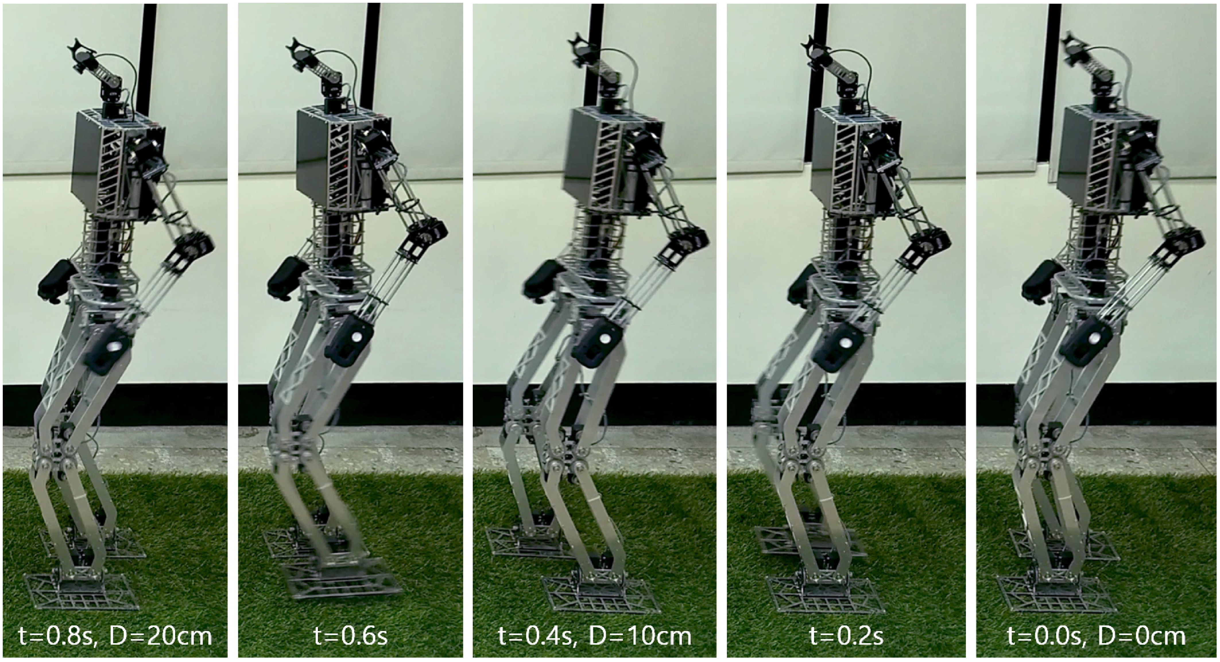
Figure 7. Bipedal full gait cycle of Robinion Sr (Speed: 25cm/s).
6.2. Perception
The results are compared with the previous ball detection method, Hough Circle, to evaluate the proposed perception method on the accelerator. For the experiments, the dataset images are gathered while the robot remains stationary. It is possible for the robot to play soccer autonomously using the model trained from the dataset, which recognizes the environment while standing, walking, and shooting. Table 4 shows the comparison between the two methods with the same validation set.
Table 4. Comparison results of the proposed method with the Hough circle method to detect the soccer ball

To evaluate our object detection model, we compare and analyze precision, recall, accuracy, and inference speed, which are indicators commonly used for evaluation in deep learning. To analyze precision, recall, and accuracy, the values of the true positive, true negative, false positive, and false negative are used and defined as the standard as in Equation 4.
 \begin{equation} \begin{aligned} &Precision = \frac{TP}{TP + FP}\\[5pt] &Recall = \frac{TP}{TP + FN}\\[5pt] &Accuracy = \frac{TP+TN}{TP + FN + FP + TN} \end{aligned} \end{equation}
As expected, the overall precision, recall, and accuracy of the deep learning-based system trump the Hough Circles approach. The metrics measured on the validation set show that the customized YOLO model could find all instances of the soccer ball as the true positive, while the Hough Circles method could find roughly half of them. Furthermore, while the deep learning model is still susceptible to false positives, it is a much lower rate of roughly 8% compared to 28% with the image processing method. It can be seen that the lightweight deep learning approach proposed by both the precision, a matric for all detections, and the recall, a matric for all ground truths, is significantly higher. Figure 8 shows the results for comparison between deep learning-based soccer ball recognition and image processing-based soccer ball recognition.

Figure 8. Comparison of the ball detection results of tiny YOLO-v3 & Hough circle approach. The top row shows examples of true positive from both models and false positives from the Hough circle approach.
One of the main advantages of the proposed YOLO model is that it is about twice as fast as the Hough Circle, with a constant inference rate of 38 milliseconds. As a result, it can process approximately 26 frames per second, which is sufficient for real-time applications. Since the Coral USB accelerator device carries out the inference, it does not put a heavy load on the CPU (or GPU), which leaves the CPU free to handle other tasks. As a whole, Robinion Sr. detects the ball for autonomous soccer play with high accuracy and a low rate of false positives compared to the previous perception system.
In order to verify the robustness of the perception system, deep-learning-based ball detection experiments are conducted in diverse regions other than the soccer field and when the robot is walking. To reach the high-accuracy trained model, the dataset includes data from non-field regions with the ball as well as the field and ball. The experiment of robust recognition of cluttered regions with multiple objects is shown in Figure 9. We demonstrate that the proposed perception method recognizes the ball even nearby a chair with a color similar to the ball, a shelf with various objects, and a blurred image.

Figure 9. Results of the perception system showcase the robustness in challenging scenarios: around similar colored objects, a cluttered shelf, and blurry images.
For autonomous soccer play, the robot has to detect objects robustly while walking as well as in various regions of the image (see Figure 10. An algorithm is implemented to kick the ball, with the omnidirectional walking gait to the ball from 2 $m$
away, by setting the walking speed at a maximum step size of 7
$m$
away, by setting the walking speed at a maximum step size of 7 $cm$
and a one-step cycle of 0.4
$cm$
and a one-step cycle of 0.4 $ms$
. In order to select the precise position for the kick, the step size and the
$ms$
. In order to select the precise position for the kick, the step size and the $\theta$
value of the hip yaw joint are controlled together while walking toward the ball. To measure the robustness of the experiment, the recorded video is split into data of 30 frames per second to measure the recognition rate, and a recognition rate of 100% was obtained in the experiment.
$\theta$
value of the hip yaw joint are controlled together while walking toward the ball. To measure the robustness of the experiment, the recorded video is split into data of 30 frames per second to measure the recognition rate, and a recognition rate of 100% was obtained in the experiment.

Figure 10. Showcase of the perception system robustness during omnidirectional walking gait.
7. Conclusions
This paper has presented a lightweight humanoid robot platform named Robinion Sr. with the adaptable and robust mechatronic system, walking gait, and software architecture of the humanoid robot, targeted for use in multiple fields, including robotics competitions, industry, and research laboratories. We optimized the hardware and software of the robot platform to minimize manufacturing cost and time, which are essential considerations in the mechatronics design of humanoid robots. With external gears and intelligent actuators, we enhanced the mechanical structure and designed a parallel kinematics configuration to reduce the number of joints in each leg. In addition, multiple functions are not computed in one controller, and not only the amount of computation through distributed control but also the cost and weight were minimized through electrical optimization. Therefore, our mechanical and electrical designs had a lightweight system, efficient cost, and low power consumption electrical architecture. In order to improve the system speed with low latency and to develop the stable gait of the humanoid robot, we implemented an analytic inverse kinematics solver and trajectory generator on the MCU. We implemented a lightweight deep learning-based perception system using the accelerator USB device, circumventing the need for a heavy GPU. As a result, it has been proven that it can be used in real-time object recognition applications with high accuracy and sufficiently fast object inference speed compared to the previous system. In future work, we plan to develop a robust and widely step-size close-loop walking gait, motion planning for manipulation tasks, and distribute ROS & ROS2 packages for open source.
Acknowledgements
This work was financially supported by the “Chinese Language and Technology Center” of National Taiwan Normal University (NTNU) from The Featured Areas Research Center Program within the framework of the Higher Education Sprout Project by the Ministry of Education (MOE) in Taiwan, and Ministry of Science and Technology, Taiwan, under Grants no. MOST 111-2918-I-003-003-, MOST 110-2923-E-003-001-MY3, and MOST 110-2221-E-003-023. We are grateful to the National Center for High-performance Computing for computer time and facilities to conduct this research.


 Open access