


NOMENCLATURE
Abbreviation
- I SP
specific impulse (s) ${OWE}_{W}$
operating weight empty by weight analysis (N)
-
${OWE}_{V}$
operating weight empty by volume analysis (N)
- Q
dynamic pressure (
$\rm{N}/{\rm m}^{2}$
)-
${S}_{pln}$
planform area (
${{\rm{m}}^{\rm{2}}}$
)-
${TOGW}$
take-off gross weight (N)
- V
volume (
${\rm m}^{3}$
)-
${{W}}$
weight (N)
-
$W/{S_{pln}}$
wing loading (
${\rm{N}}/{{\rm{m}}^{\rm{2}}}$
)


Greek symbols
-
$\tau $
Küchemann’s slenderness parameter (m3/m3)

Acronyms
- AB
all-body
- AFRL
Air Force Research Laboratory
- AHW
Advanced Hypersonic Weapon
- AIAA
American Institute of Aeronautics and Astronautics
- ARRW
Air-launched Rapid Response Weapon
- AVD
Aerospace Vehicle Design
- BB
blended-body
- CG
center of gravity
- CH4
methane
- CMDS
complex multidisciplinary system
- DARPA
Defense Advanced Research Projects Agency
- FDL
Flight Dynamics Laboratory
- GHV
Generic Hypersonic Vehicle
- HAWC
Hypersonic Air-breathing Weapon Concept
- HCSW
Hypersonic Conventional Strike Weapon
- H2
hydrogen
- IC
industry capability
- JANNAF
Joint Army Navy NASA Air Force
- LEO
low Earth orbit
- NASA
National Aeronautics and Space Administration
- NASP
National Aerospace Plane
- OpFires
operational fires
- OWE
operational weight empty
- PSF
pounds per square feet
- RLV
reusable launch vehicle
- RP-1
highly refined form of kerosene
- SCA
shuttle carrier aircraft
- SFFP
summer faculty fellowship program
- SSO
Space Shuttle Orbiter
- STARS
strategic targets system
- TBG
tactical boost glide
- TC
technology capability
- TOGM
take-off gross mass
- TPS
thermal protection system
- USAF
United States Air Force
- WB
wing-body
1.0 INTRODUCTION
The United States industrial base has recognised the advent of yet another era of large-scale investments into the hypersonic regime. Currently, there are six publicly known hypersonic research and development programs overseen by the U.S. government(Reference Borrie, Dowler and Podvig1). The U.S. Army, Navy, and Air Force along with DARPA and NASA manage these programs. Five of these programs are weapon programs that are developing hypersonic boost-glide vehicle and air-launched scramjet missile demonstrator capabilities. DARPA has awarded contracts for the Hypersonic Air-Breathing Weapon Concept (HAWC), and it is collaborating with the USAF and U.S. Army on the Tactical Boost Glide (TBG) and Operational Fires (OpFires) programs. The U.S. Army is also working on the Advanced Hypersonic Weapon (AHW), which is a long-range boost-glide vehicle. The USAF is working on the Air-Launched Rapid Response Weapon (ARRW) and the Hypersonic Conventional Strike Weapon (HCSW). The sixth program is the NASA Hypersonic Technology Project, which focuses on technologies such as high-speed propulsion, reusable vehicle technologies, high-temperature materials, and systems analysis for commercial air transportation.
Although these specific applications of hypersonic technologies appear diverse, they all have common research requirements. Systems like the boost-glide vehicle will not need air-breathing propulsion, but they will be just as dependent on the current disciplinary industry capability (IC) and selective future technology capability (TC), stemming from individual disciplines (like aerodynamics, aerothermodynamics, and stability and control) and the underlying multi-disciplinary design synthesis capability. This commonality in research goals implies that planning for new flight research programs should consider collaboration between agencies.
In this vein, it becomes essential to parametrically consider the planning effects between the integrated air launch platform and the hypersonic cruise research vehicle. This provides an opportunity to identify the most advantageous path forward for all invested parties, by subsequently lowering the cost and risk associated with exclusive or one-off carrier vehicles. Note that the benefits of having commonality between carrier/launch platforms include lower operating cost due to increased fleet flight rate, lower schedule risk from loss of a custom one-off platform, increased operational flexibility, and possible capability growth of research platforms. Since the operational benefits discussed for a synergistic air carry platform depend on overall demand, a multi-capability platform appears beneficial, with ability to handle program needs for multiple or all parties.
Specifying the relative required capability of individual air-carry/launch platforms necessitates identifying prospective research vehicles for the near future. For the present study, this is done by exploring past-to-present hypersonic programs and selecting representative IC or TC vehicle case studies. This approach provides a first look into both what near to mid-term IC and TC test vehicles may exist, as well as what will be required of future air-carrier platforms. Minding the near-term to mid-term demand for future hypersonic demonstrators, this study determines the solution space topography available for pre-selected hypersonic demonstrator baseline vehicles. The resulting topography of converged hypersonic demonstrator “family members” is superimposed with air-carrier vehicle constraints, overall creating the combined system solution space topography. In summary, this solution space screening approach enables the parametric matching of the air-carry/launch vehicle with the prospective hypersonic demonstrator, overall enabling the decision-maker to substantiate recommendations based on available versus required carrier vehicle options.
1.1 Study objective
The objective of this study has been to identify primary requirements for air carrier vehicle platforms in the context of near-term hypersonic cruise vehicle demonstrator solution spaces. This has been accomplished by screening a selected range of research vehicle alternatives, each consistently compared with air-carrier vehicle constraints. The resulting combined solution space topographies provide a holistic physical understanding of the operational air-carrier vehicle platforms investment value for the support of a variety of flight test programs.
1.2 Overall study approach
In order to accomplish the study objective outlined above, a review of past-to-present carrier vehicle study results and recommendations has been undertaken to accelerate the understanding of this effort. Likewise, a review of past-to-present hypersonic demonstrator programs drives the selection of near-term hypersonic vehicle attributes for system sizing considerations. Having selected representative near-term prospective flight research vehicles, they are synthesised, producing a solution space consisting of converged vehicle designs. Regarding the synthesis process, the overall methodology employed is a multi-disciplinary sequential solution definition process for a single converged point design that is iterated on selected design trades such as (a) configuration, (b) mission, and (c) technology options. The trade sweep of design variables results in the definition of a converged solution space topography composed of multiple design configurations and design concepts. These converged solution spaces can then be overlaid for consistent comparison between hypersonic vehicle configurations and concepts, as well as relevant carrier vehicle constraints. The conclusions of the available versus required carrier vehicle options and the hypersonic demonstrator solution space results are the foundation for preliminary recommendations regarding carrier vehicles for near-term flight research programs.
2.0 CONSIDERATION OF HYPERSONIC PROGRAMS AND CARRIER VEHICLES
This section focuses on identifying and characterising relevant past-to-present hypersonic vehicle and air-carrier vehicle platform related projects, data, and knowledge. The vast sums of monetary and intellectual investments spent on these efforts present an opportunity to not only learn from past mistakes and successes, but to infer new knowledge from discounted efforts. This study has been divided into two primary categories: (a) hypersonic vehicles, and (b) air carrier vehicle platforms.
2.1 Hypersonic vehicles
The state of hypersonic vehicles today is such that there are no publicly acknowledged hypersonic vehicles in operation. This may soon be changing with the introduction of the X-60A, which recently passed the conceptual design review. The X-60A is designed as an expendable small-scale hypersonic flight regime test platform. Overall, the significance of hypersonic test vehicles is noted by the number and complexity of past-to-present U.S. research projects, see Table 1.
Table 1 Significant past and present U.S. hypersonic projects and programs(Reference Chudoba, Coleman, Oza, Gonzalez and Czysz2)
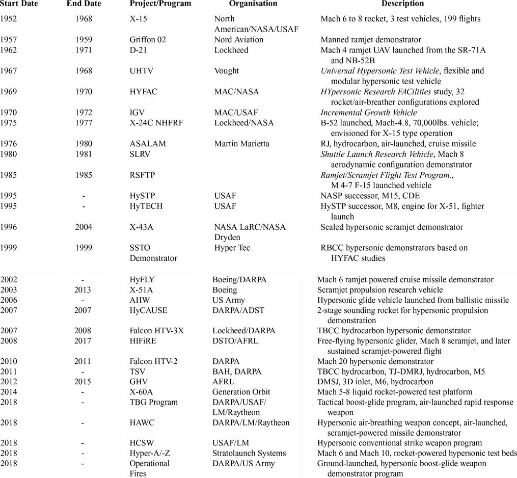
Enabling operational hypersonic systems will allow for both rapid response and unpredictability from the military, as well as new commercial opportunities such as rapid overseas passenger or cargo transport. Additionally, as envisioned with the National Aero-Space Plane (NASP) program (cancelled in 1993), hypersonics represents a key technology that may one day enable cheap and reliable access to Low Earth Orbit (LEO). Examining Table 1, it is evident that a large number of hypersonic test platforms have been investigated, ranging from demonstration vehicles, proposed operational vehicles, and military weapons platforms. Regardless of the specifics of the hypersonic project, the vast majority require some type of air-carrier or air-launch platform, whether that has been a missile-derived booster, or a commercial or military aircraft adapted as an airdrop platform. Reviewing the major hypersonic projects also reveals the common trend of overly ambitious research objectives. Several programs have been flawed from the outset by incorporating too many simultaneous advances in propulsion, aerodynamics, and materials into the design, thereby increasing overall risk, schedule delays, and cost escalation.
2.2 Air-carrier vehicles
Air-carrier launched flight test experiments have been ongoing since the late 1940s, beginning with the Bell X-1 in the U.S. Fig. 1 chronicles past-to-present air-launch carrier vehicles and the project vehicles they have carried. The first three project vehicles to conduct captive carry tests used modified variants of the B-29 and B-50B bombers. These project vehicles have launched from the underside of former bombers. The heaviest project vehicle carried during this time has been the X-2 at 11,300kg (24,910lb). From the early 1960s to its retirement in 2004, the NB-52A/B operated as the primary carrier vehicle for project vehicle flight tests. The NB-52 launched renowned project vehicles such as the X-15, HL-10, X-24B, X-38, and X-43 from a wing pylon designed to carry just over 22,680kg (50,000lb)(Reference Lockett3). The heaviest vehicle launched has been the X-15A-2, with a weight of 24,090kg (53,100lb). Another special carrier aircraft operating since the late 1970s was the Boeing 747 shuttle carrier aircraft, which carried the Space Shuttle Orbiter (SSO) on the top of its fuselage. This modified Boeing 747-100 aircraft carried the 106,590kg (235,000lb) orbiter. The carrier retired in 2012 with the completion of the Space Shuttle (STS) program.
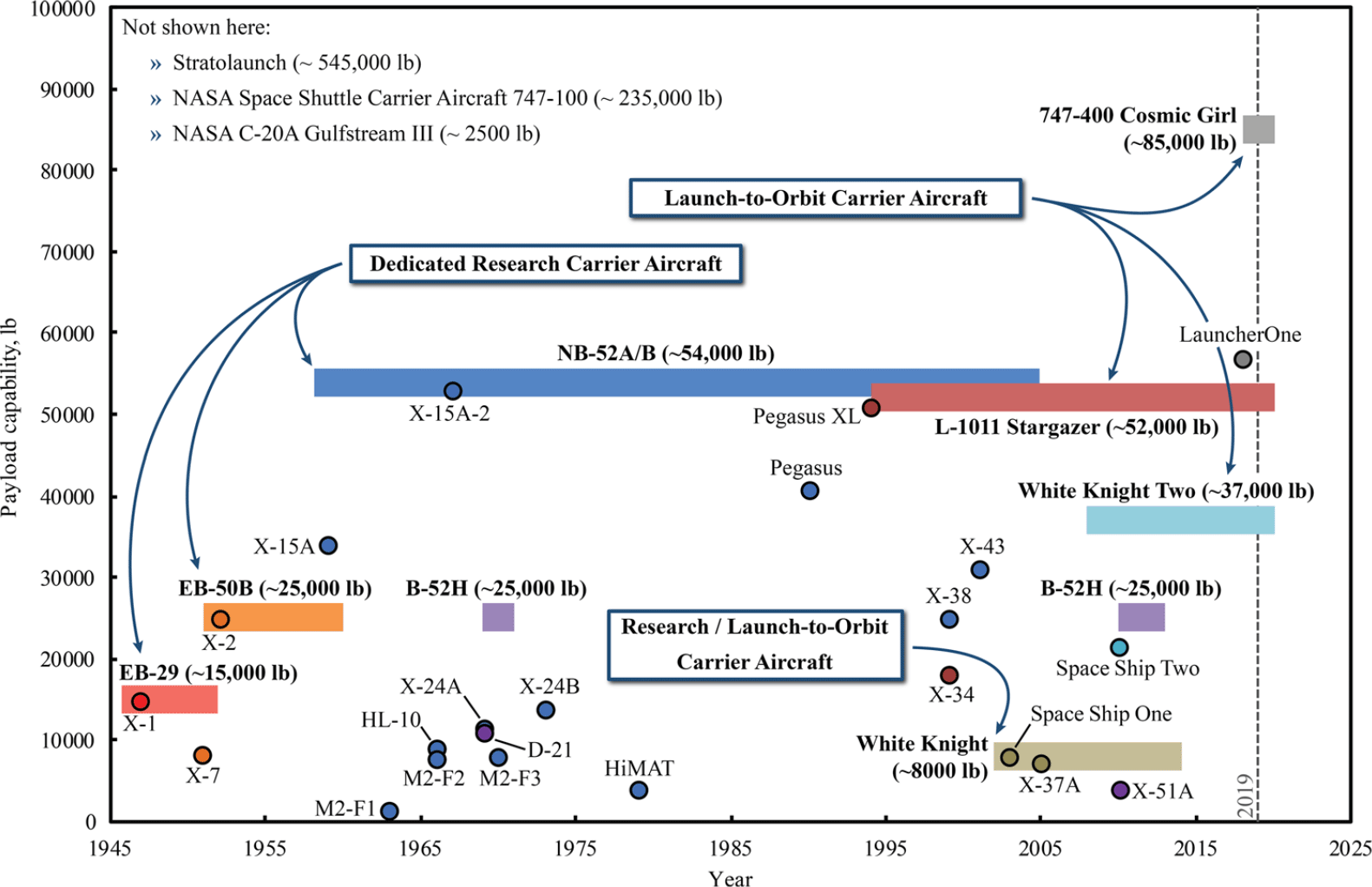
Figure 1. Historical operation of carrier/carried vehicles.
Today, there are five operational aircraft that are used as carrier vehicles. These are the B-52H, the Northrop Grumman L-1011 Stargazer, the NASA C-20A, the Virgin Orbit B747-400 Cosmic Girl, and Scaled Composites Stratolaunch. The B-52H has been used to carry the D-21 in the late 1960s and more recently the X-51 from 2010 to 2013. The B-52H is similar to the NB-52B in that it carries the project vehicle on a wing pylon, but its pylon is only able to hold a maximum weight of 11,340kg (25,000lb)(4). The L-1011 Stargazer is the carrier vehicle for the Pegasus and Pegasus XL launch vehicles. The Stargazer has a bottom fuselage carry configuration. It can launch a 23,190kg (50,990lb) Pegasus XL. The NASA C-20A has the capability to carry a payload under the fuselage or on a wing pylon. It has been used for the GOLauncher1 turned X-60A project vehicle.
The Virgin Orbit B747-400 Cosmic Girl is another wing pylon carry configuration launcher, which has a maximum pylon payload weight of 38,555kg (85,000lb). Its primary payload is the Virgin Orbit LauncherOne space launch vehicle, which has a maximum weight of 25,855kg (57,000lb). Finally, the Stratolaunch aircraft is a high wing pylon carry configuration where the maximum pylon carry weight is 247,210kg (545,000lb)(Reference Corda, Longo and Krevor5). It is designed to launch large hypersonic testbed vehicles such as the Stratolaunch Systems’ proposed Hyper-Z Mach 10 concept.
While the project vehicles in Fig. 1 are air launched, two additional launch approaches include ground and sea. A common practice is to launch from either ground or sea using ballistic missile-derived platforms. There has been other hypersonic project test vehicles that have been ground or sea launched using a ballistic missile derived launch vehicle (e.g. the Minotaur IV missile from the Minuteman II and Peacekeeper ICBMs, or the Strategic Targets System (STARS) booster stack from the Polaris ballistic missile). The hypersonic missile projects are included in Table 1 with the other project vehicle studies to remind that there is a potential for air launch carrier platform commonality between the military branches and other government agencies for in-flight hypersonic research.
Currently, the U.S. government does not have a dedicated common carrier vehicle platform for in-flight hypersonic research. The following sections summarise the fundamental constraints associated with selecting an air-launch carrier or booster carrier vehicle.
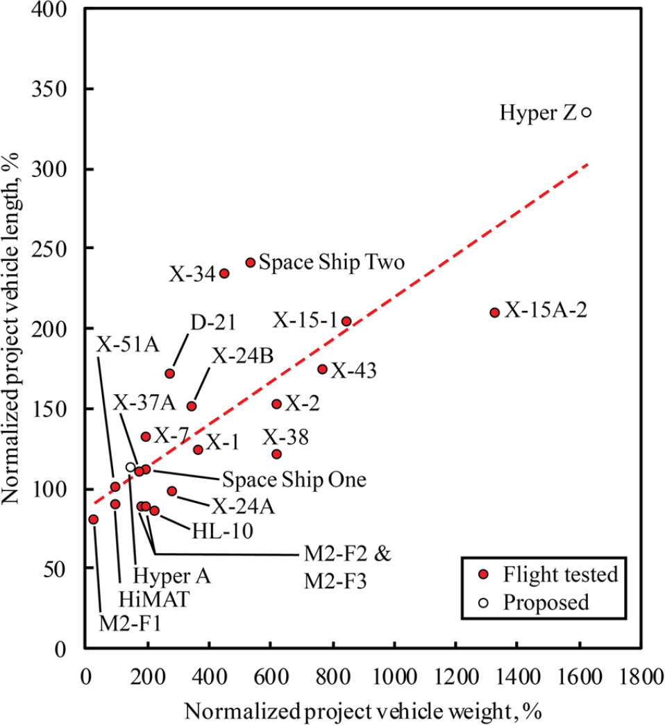
Figure 2. Relative project vehicle length and weight characteristics.
2.3 Air launch carrier vehicle constraints
This study focuses only on subsonic launch carrier aircraft. Previous horizontal launch-to-orbit studies have identified that a supersonic/hypersonic carrier vehicle with a payload of 6,800kg (15,000lb) would require development of a new aircraft, which is cost prohibitive for their presumed six flights per year(Reference Bartolotta, Wilhite, Schaffer, Huebner, Voland and Voracek6). The DARPA/NASA study in Ref. (Reference Bartolotta, Wilhite, Schaffer, Huebner, Voland and Voracek6) also considered a horizontal launch system which could be used commercially for profit, whereas the test vehicles in this study would not be able to generate any revenue for the program.
In order to select an air carrier vehicle, the constraints of the carrier vehicle on the test vehicle solution space have to be established. Fundamentally, the carrier vehicle constrains the test vehicle’s take-off gross mass (TOGM) and maximum size in terms of length, width, and height. Figures 2-4 show the relationships between vehicle weight and geometry. The figures give a notional indication of how project vehicles tend to grow in size with increasing weight. Note that the weight and geometry data in these plots are normalised to the X-51A, with a weight, length, wingspan, and height of 4,000lb, 25ft., 4.6ft., and 2ft., respectively. Awareness of vehicle growth and subsequent payload capacity requirements for a launch system is critical for a future proof or application robust launch system.
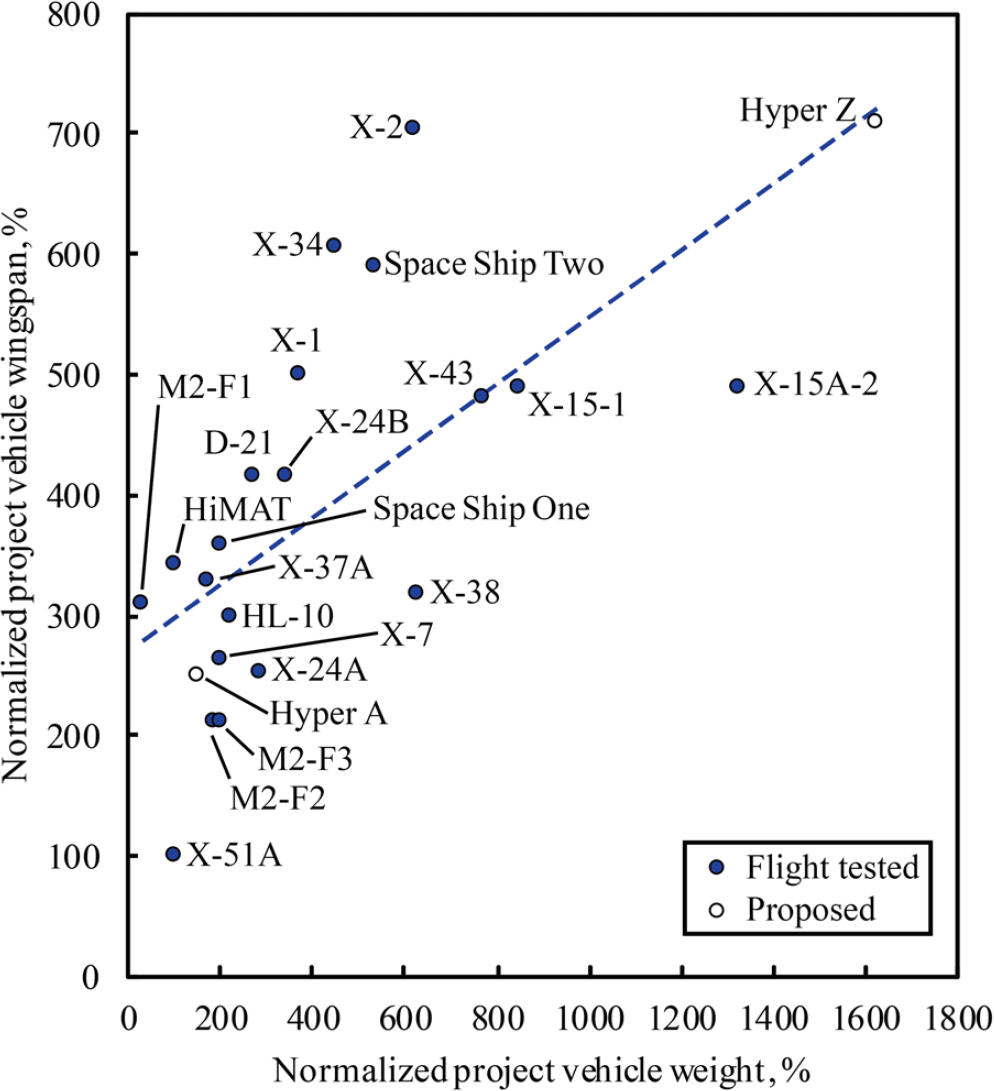
Figure 3. Relative project vehicle wingspan and weight characteristics.
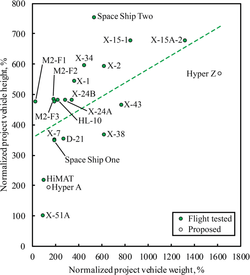
Figure 4. Relative project vehicle height and weight characteristics.
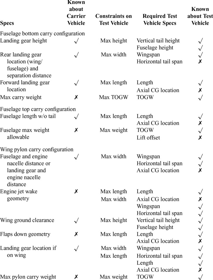
Table 2 Fundamental carrier constraints on test vehicles
The carrier vehicle constraints depend on the overall air-carry vehicle configuration. The test vehicle may be launched from the top of the fuselage (e.g. the NASA shuttle carrier aircraft 747-100), the bottom of the fuselage (e.g. the L-1011 Stargazer), or a pylon on the wing (e.g. the NB-52B). Note that other launch configurations have been investigated in Refs (Reference Sarigul-Klijn, Sarigul-Klijn, Hudson, McKinney, Voss, Chapman, Morgan, Tighe, Kramb, Doyle, Quayle and Brown7,Reference Sarigul-Klijn and Sarigul-Klijn8) for launch to orbit applications, such as towed carry and internal carry. Those launch configurations have not been considered in the present context.
Table 2 has been created in order to investigate the (a) geometric and (b) structural loading constraints. These constraints can be readily assessed for making decisions about test vehicle and carrier vehicle compatibility in the context of this study. Table 2 provides a breakdown of the various constraints for each of the three air-carry configuration types, whether on the top, bottom, or on a wing pylon. The second column of the table establishes the characteristics of the air carrier, consisting of maximum pylon carry weight, wing ground clearance, or fuselage length. The third column establishes whether these characteristics of the aircraft are readily known. The dimensions of most commercial aircraft are available in airport planning documents (e.g. see Refs. 9,10). However, geometry and weight data for military aircraft are not readily available.
Next, the fourth column states the test vehicle characteristics that are constrained by the air-carrier vehicle constraints such as the maximum width, height, and weight of the test vehicle. The geometric constraints can further be subdivided into the test vehicle characteristics that are required in order to determine if both vehicles are compatible. For instance, the maximum length of the test vehicle for a pylon launch will depend on the test vehicle’s stack length, axial center of gravity (CG) location, and its wingspan or horizontal tail span. Since the test vehicle will be positioned on the pylon based on its CG location, there is not a definitive maximum length criterion that can be measured on the air-carrier vehicle. However, if the CG is known, then the maximum length of the test vehicle can be determined from the jet wake geometry or other considerations like the motion of the flaps during take-off/landing. Finally, the last column identifies which test vehicle design characteristics are known and not known.
It is of first order or highest importance to correctly determine which air carrier vehicles are physically compatible with a selected test vehicle. However, there are other important considerations when making the selection. These are of operational nature such as flight rate desired for the test vehicle, growth potential for the test vehicle, launch location restrictions, cost of air carrier vehicle purchase and modifications, air carrier vehicle availability, maximum flight speed, and maximum ceiling. The next three subsections discuss the applicable constraints for the three air-carry configurations and how they affect air-carrier aircraft selection.
2.4 Bottom carry configuration
There have been four carrier aircraft examples with the fuselage bottom carry configuration. These are the EB-29, EB-50, L-1011 Stargazer, and C-20A. This carry configuration geometrically constrains the maximum height, width, and length of the test vehicle. The only consistent constraint across different aircraft models for the bottom carry configuration is the maximum test vehicle height.
For the maximum test vehicle height, the minimum landing gear height of each air carrier vehicle is used as a maximum allowable height for the test vehicle, see Fig. 5. The rear landing gear separation distance of the carrier aircraft is used as the maximum allowable width of the test vehicle. To constrain the length of the test vehicle, the distance between the nose gear and the rear gear of the carrier aircraft is used. Note that these width and length constraints are not hard constraints due to their dependence on the CG location and attachment point on the carrier aircraft. For instance, the test vehicle’s max wingspan may not cross where the landing gear of the carrier aircraft is located. For the length constraint, if the landing gear is not modified, the rear landing gear of the carrier aircraft will constrain the maximum length of the test vehicle if the carrier aircraft has a fuselage retracting landing gear like the B747-400. Smaller aircraft like the B737-900 do not have a fuselage retracting landing gear; they have wing landing gear that retracts into the fuselage. This length constraint does not consider the longitudinal static stability effects of placing the test vehicle too far forward on the carrier aircraft. The gear separation distance (from port to starboard) can be used as a rough estimate of the maximum width, see Fig. 5. In addition, as shown in Table 2, the maximum weight that the bottom of the fuselage can carry is not known, but the structural payload of the aircraft is used as a first order estimate.
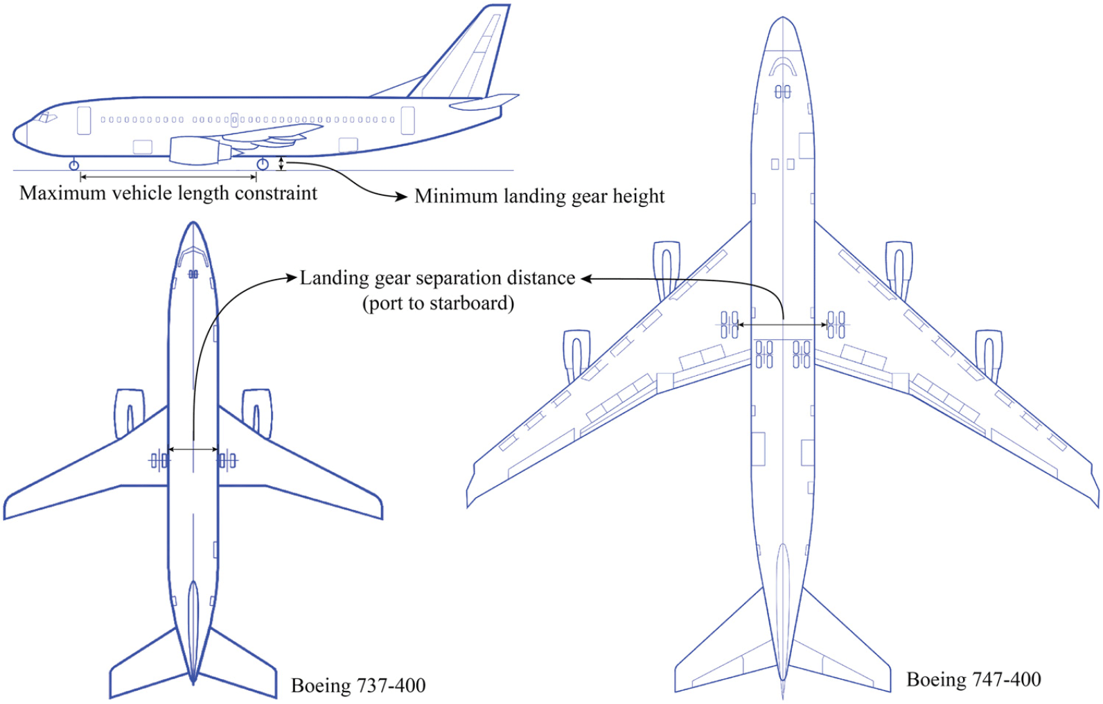
Figure 5. Bottom carry constraints.
As noted in Ref. (Reference Sarigul-Klijn and Sarigul-Klijn8), advantages to the bottom carry configuration include proven and easy separation from the carrier aircraft, attachment points are on the top of the test vehicle (as opposed to the underside thermal protection system, TPS, of the test vehicle), and the wing used for separation can be sized smaller(Reference Sarigul-Klijn and Sarigul-Klijn8). Disadvantages are primarily the restrictions in height and cost of modification to the carrier aircraft(Reference Sarigul-Klijn and Sarigul-Klijn8).
2.5 Top carry configuration
As shown in Table 2, the two primary carrier aircraft examples with the top carry configuration are the Lockheed SR-71A (with the D-21) and the Boeing 747-100 SCA (with the Space Shuttle Orbiter). This configuration is geometrically constrained only in the length direction. The distance between the fuselage nose and the leading edge of the vertical tail of the air carrier is used as the maximum allowable length. Figure 6 shows an example of how close the Space Shuttle Orbiter is getting to the maximum test vehicle length provided by the B747-100 fuselage. If the test vehicle is aft heavy due to a large booster, it may need to be shifted more towards the nose of the carrier aircraft. Furthermore, as the test vehicle may increase in size over the duration of the research program, the total drag and vertical CG location of the combined carrier/test vehicle combination needs to be considered.
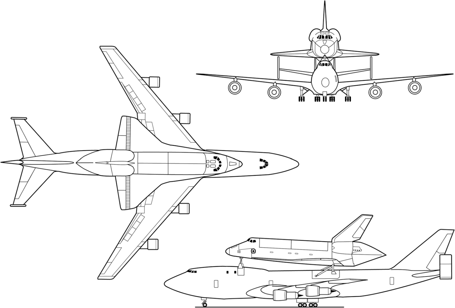
Figure 6. Space Shuttle Carrier Aircraft. Reproduced from Ref. (11).
Like the bottom carry configuration, the structural payload is used as an initial estimate for the maximum weight that the fuselage can handle for the top carry configuration. The Space Shuttle Orbiter provides an example of a maximum top fuselage payload of 106,590kg (235,000lb).
The top carry configuration’s primary advantage is the ability to carry large test vehicles. For example, a 2011 hypersonic test vehicle study(Reference Chudoba, Coleman, Oza, Gonzalez and Czysz2) found that the pylon launch configuration of the B-52H is not big enough to geometrically accommodate five of the six air launched demonstrator vehicles the study considered. The disadvantages of this configuration are the hard point attachments on the TPS side (bottom) of the test vehicle and the associated high modification costs of the carrier aircraft(Reference Sarigul-Klijn and Sarigul-Klijn8). It also requires active aerodynamic controls and a test vehicle wing sized for the separation manoeuver from the carrier aircraft(Reference Sarigul-Klijn and Sarigul-Klijn8). According to Ref. (Reference Bartolotta, Wilhite, Schaffer, Huebner, Voland and Voracek6), the top carry configuration is also demanding a minimum separation distance between the carrier aircraft and the test vehicle before igniting any booster engines on the test vehicle.
2.6 Wing pylon carry configuration
The wing pylon carry configuration has been the most popular carry configuration since the introduction of the NB-52A/B in 1959 with the X-15 program. Like the bottom carry configuration, this configuration also constrains the maximum width, height, and length of the vehicle. The width is constrained by three carrier aircraft factors. These are the distance between the fuselage and inner engine nacelle, the geometry of the jet wake, and the distance between the carrier aircraft main landing gear and the engine nacelle. Figure 7 shows the jet wake, ground clearance, and fuselage/engine nacelle constraints that have been presented during the configuration development study for the X-24C test vehicle.
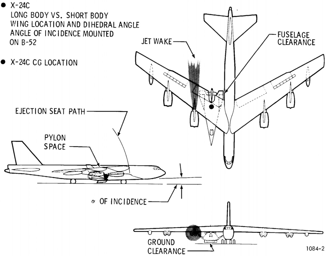
Figure 7. NB-52 pylon carry constraints. Reproduced from Ref. (Reference Combs, Campbell, Cassidy, Sumpter, Seitz, Kachel, James, Walters, Love and Passon12).
The maximum height of the vehicle is constrained by the carrier aircraft wing ground clearance. A maximum length constraint for the pylon configuration is estimated for this study based on several known vehicles such as the X-24C and LauncherOne. The maximum length constraint for pylon configurations is also dependent on test vehicle CG location. For example, the LauncherOne rocket is aft heavy, so its CG location requires the vehicle to be moved forward. The test vehicle’s nose extends to around 23ft. past the pylon leading edge of the B747-400 wing. A hard constraint cannot be defined at this point. To do so would require knowledge of the test vehicle’s CG location and placement underneath the wing.
As discussed earlier, the NB-52A/B has been able to carry a maximum of 22,680kg (50,000lb). The pylon launcher Cosmic Girl has been designed to launch a maximum payload of 38,555kg (85,000lb) from the pylon. The current B-52H capability is around 11,340kg (25,000lb), but proposed B-52J upgrades are considering to upgrade the pylons to support the carry of multiple 9,071kg (20,000lb) weapons(4,Reference Trevithick13) . These known pylon weight limits are used to estimate maximum pylon weight limits for the test vehicles in this study.
2.7 Vertical launch configuration considerations
Vertical launch platforms (e.g. Minotaur IV Lite) are advantageous to hypersonic test programs in that they can eliminate the need of an additional booster system (see booster arrangement on the X-43A and X-51 in Fig. 8). Additionally, vertical launch platforms are simplifying fueling routines whilst enabling the use of more exotic sub-chilled cryogenic propellants due to the use of ground support equipment and the relatively fast time from launch to operational conditions of the test vehicle. Vertically launched experimental tests tend to offer extended test times and higher test Mach numbers.
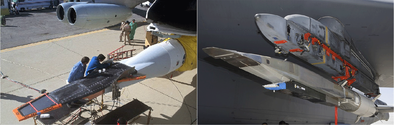
Figure 8. X-43 and X-51 hypersonic test vehicles. Courtesy of NASA/USAF.
A disadvantage of the vertical launch system is that reusability is not necessarily implied. For systems that could be reusable like the Falcon 9 or future New Glenn, it’s unclear whether the booster is able to handle separation loads at the typical dynamic pressures of a hypersonic vehicle at flight conditions from 1,000 to 2,000 PSF(Reference Ruttle, Stork and Liston14). If it is not possible to survive these conditions, either extra development effort has to strengthen the reusable boosters, or the hypersonic vehicle design has to schedule a sub-orbital trajectory and achieve the required flight conditions upon reentry. Sub-orbital operation adds additional design constraints to the test vehicle such as additional non-aerodynamic controls and added thermal protection for reentry conditions.
Additional operational penalties for vertical launch systems include launch facility dependability and possible weather-related delays. Note that super-heavy carrier aircraft might have similar drawbacks where they are limited to only the largest runways and are still take-off/landing constrained due to local weather conditions.
3.0 HYPERSONIC TEST VEHICLE PERMUTATIONS
The conceptual design phase is naturally characterised by design freedom. Such design freedom translates into abundant design variable options. However, it is not practical to address every possible design parameter combination. Identifying practical-relevant combinations of hypersonic vehicle design parameters stemming from (a) hardware, (b) mission, and (c) operation for a given study does typically involve defining a trade matrix of possible combinations. This is followed by a technology acquisition study for the relevant combinations via parametric sizing, configuration layout and configuration assessment studies of the most promising baseline designs(Reference Rana, McCall, Haley, Gonzalez, Omoragbon, Oza and Chudoba15). The goal of this research study is to present an assessment of near-term hypersonic research vehicle combinations and, specifically, how they integrate with various carrier vehicle options. Consequently, it is necessary to down select from the multitude of design options available in order to arrive at a feasible study trade matrix.
In order to identify near-term hypersonic research vehicle platform concepts, a review of technology roadmaps from relevant government branches has been conducted. The NASA roadmap from 2017 does express a desire to develop limited reusable air-breathing hypersonic propulsion by the 2030s, with fully reusable routinely operated hypersonic vehicles by the 2040s(Reference Dryer16). The USAF hypersonics roadmap has similar technology goals outlined by the same timeframes, but with focus on increasing the size of vehicles (range, endurance, payload capability) and their respective mission, with a reusability target for the 2040+ timeframe(Reference Blackhurst17). The Army technology roadmaps are more concerned with the prompt global strike capability and the fielding of the AHW as the main next step(Reference Borrie, Dowler and Podvig1). The agency’s specific test programs to achieve these technology goals are not outlined. However, with notable progress of past research projects such as the early X-planes, it appears logical that a similar approach could be taken with a focus on reusable test vehicles with rapid turnaround times. This approach would allow a responsive and more rapid research approach similar to the recent development of reusable boosters by SpaceX and Blue Origin. Flight test data is more valuable compared to ground or simulation generated data(Reference Dolvin18). Consequently, reusable test vehicles have the potential to both lower cost and more importantly reduce turn-around time between tests.
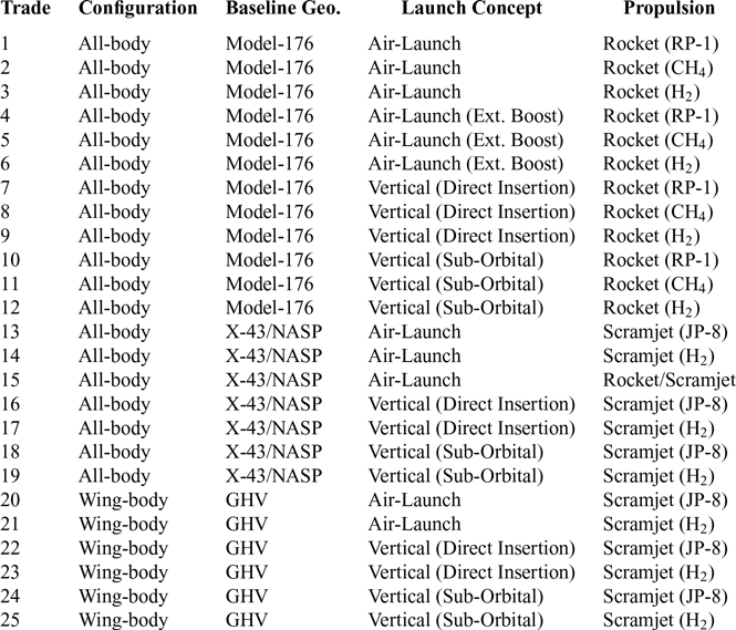
Drawing from the review of past hypersonic vehicle projects and programs, combinations of vehicle hardware, mission, and operation have been considered and assembled into a vehicle trade matrix, see Table 3. This trade space represents pertinent options for near-term demonstrators. For the near-term options, rocket propulsion is utilised, with a scramjet option as the mid-term vehicle propulsion choice. Geometry configurations are limited to all-body (AB) and wing-body (WB) concepts. Scramjet propellant has been limited to hydrocarbons. The reference mission considered for all vehicles focuses on Mach 6 cruise design speed. Recovery (reusability) is required through provisioning for horizontal lift-supported landing field performance and by considering the landing gear/skid weight. Time of cruise and payload weight are the mission trade variables, with the Küchemann volumetric efficiency term  $\tau $
representing possible changes in vehicle cross section. Details pertaining to specific vehicle trades and configurations are presented in the problem setup section below.
$\tau $
representing possible changes in vehicle cross section. Details pertaining to specific vehicle trades and configurations are presented in the problem setup section below.
Table 3 Demonstrator trade matrix
4.0 SIZING METHODOLOGY AND PROBLEM SETUP
In order to derive physical insights into the carrier aircraft and test vehicle relationship, it is necessary to identify a set of baseline vehicle concepts, their corresponding mission and hardware, and a sizing logic for these concepts. These three areas will define the general study approach. The baseline vehicle technology, mission, and hardware options are down-selected from the trade matrix, see Table 3.
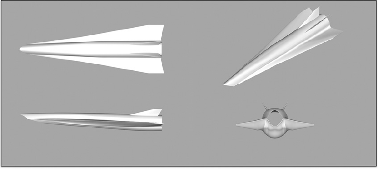
Figure 9. Original air-breathing GHV.
4.1 Trade studies
The selection of concepts from the trade matrix, as introduced previously, require several logical eliminations. The following four considerations have guided towards a reduced and therefore manageable trade matrix. First, the common goals and desires described in the technology development timelines stem from NASA and the USAF. Second, the mission and operational requirements of past test vehicle programs. Third, selecting elements that are compatible with multiple air-carrier/booster vehicle options. Lastly, the availability of math models to analyse the composed vehicles. The logical deductions result in four basic and representative vehicle configurations with multiple mission and operational trades for each.
4.1.1 Trade studies: baseline vehicle definition
In selecting appropriate geometry configurations, the all-body (AB) and the wing-body (WB) type are selected as they are expected to form the boundaries of the feasible solution space. That is, a blended-body (BB) design point will fall within the bounds of the wing-body and all-body solutions. As such, the blended-body is not a necessary design trade. The baseline vehicles considered for the all-body and wing-body types are the FDL-7MC(Reference Goetsch19) or McDonnell Douglas Model-176 and the USAF AFRL Generic Hypersonic Vehicle (GHV(Reference Ruttle, Stork and Liston14)), respectively. The GHV represents a current system of study that is well documented for the Mach 5-6 range. It shares many features with the HIFiRE flight 6 and 8 vehicles(Reference Dolvin18). The GHV has previously been studied by the Aerospace Vehicle Design (AVD) Laboratory in 2015-16(Reference Gonzalez20) which formally verified the AVD Laboratory synthesis system. The Model-176 all-body configuration has been selected as it represents a high-performance (high-L/D) and high Mach number range capable (Mach 12+) geometry, where the original design was intended for high down-range and cross-range space reentry capability. This all-body configuration has been thoroughly analysed by McDonnell Douglas throughout the relevant disciplines due to its NASP era origins(Reference Czysz21). Due to the highly integrated nature of hypersonic flight vehicles (specifically air-breathing vehicles), both of these baseline configurations open up a pragmatic path to modify and accommodate either a closed fuselage and rocket (GHV) or an integrated underslung 2D scramjet (Model-176). The emerging vehicle perturbations based on both baseline geometries open a representative spectrum by incorporating both near-term to mid-term propulsion systems.
Figures 9 and 10 below visualise the original baseline air-breathing GHV and the modified rocket-powered GHV respectively. The adapted GHV geometry has its fuselage closed and faired off into a semi-cylindrical body. The resultant adapted geometry has higher volumetric efficiency and is better suited to carrying pressurised propellant tanks. Other aspects of the geometry remain the same, with identical wing and tail surfaces. Although the removal of the Busemann intake and flow path does require a re-derivation of the wave-rider wing arrangement, this configuration is representative of what a WB configuration can achieve.
The Model-176 has been modified to incorporate an underslung 2D scramjet with the scramjet integration modeled after the X-51 test vehicle. Visualised in Figs 11 and 12 are the original baseline rocket-powered Model-176 and the modified air-breathing Model-176 respectively. The Model-176 derived configuration retains a deployable scissor wing for low-speed glide and landing considerations, see also previous sizing studies(Reference Chudoba, Coleman, Oza, Gonzalez and Czysz2,Reference Chudoba and Gonzalez22) . These studies show that the blended-body and all-body configurations result in high wing-loadings, overall constraining the resulting vehicles for the horizontal unpowered landing.
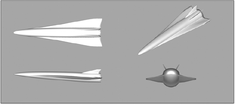
Figure 10. Rocket modified GHV.
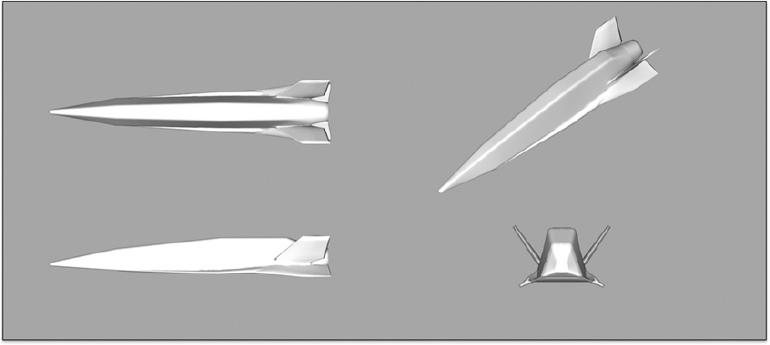
Figure 11. Original rocket-powered Model-176.
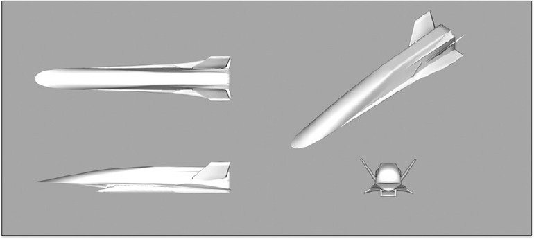
Figure 12. Scramjet modified Model-176.
4.1.2 Trade studies: mission definition
This study considers two mission scenarios. The two missions are distinguished by whether an external booster is used or not for the vehicle’s climb and acceleration to the primary mission start condition. The air-breathing configuration is limited to the expendable rocket booster scenario. The non-air breathing rocket configurations are not limited; they are applied to both mission launch scenarios (i.e. external expendable boost system and internal reusable boost system). All scenarios start with an airdrop condition at Mach 0.8 and 30kft, a final endurance cruise condition at Mach 6, and a horizontal gliding recovery at a landing site. The two scenarios are discussed in more detail below.
The external expendable booster profile is illustrated in Fig. 13. For ease of comparison and relevance, a mission with a similar performance specification, stemming from the original GHV study(Reference Ruttle, Stork and Liston14), is used. The vehicle is airdropped, boosted to the starting condition, accelerates at constant altitude until it reaches the design Mach number, then executes a constant Mach endurance cruise segment, and finally performs a power-off gliding descent to the horizontal landing point.
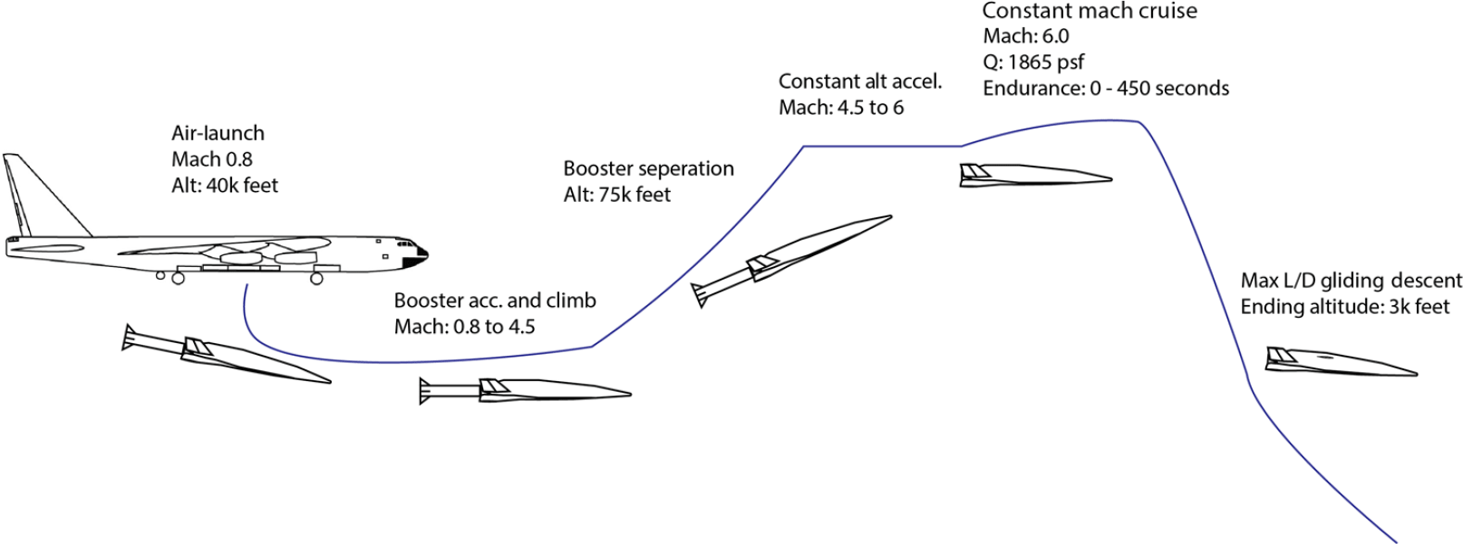
Figure 13. Mission: expendable vehicle boost with acceleration climb to cruise altitude.
The major change, compared to the original GHV mission, is the elimination of the secondary maneuvering flight additions, as their inclusion does not significantly change the size of the vehicle. This mission configuration assumes an expendable booster sized to place the test vehicle at 75kft with a Mach number of 4.5, which corresponds to the lower end of the GHV scramjet dynamic pressure range of 1,000 PSF. After staging the booster, the vehicle then accelerates to Mach 6, with an upper dynamic pressure of 1,864 PSF, followed by the specified endurance cruise and a gliding descent segment to landing approach.
In the second all-rocket scenario, as illustrated in Fig. 14, the test vehicle is accelerated to its cruise condition by an integrated onboard rocket system. The test vehicle is its own accelerator. The main engine powers acceleration and cruise. That is, this mission sizes the vehicle to include the propulsive capacity previously provided by the external booster. In this regard, the all-rocket vehicles are fully reusable. Given that the vehicle is launched at subsonic conditions, this flight scenario is limited to only rocket-powered vehicles. Having identified and described the mission flight segments, the following section addresses the primary hardware and capability trades.
Table 4 Hardware and mission trade study summary
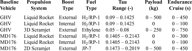
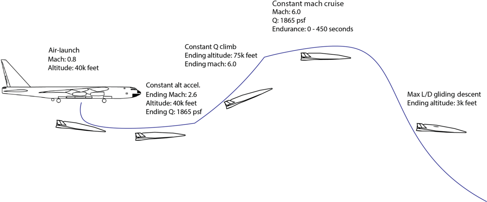
Figure 14. Mission: internal rocket vehicle boost with acceleration climb to cruise altitude.
4.1.3 Trade studies: hardware definition
As the objective is to perform an investigation into near term hypersonic reusable test vehicle concepts and the interrelation with available air-carrier vehicles, it is necessary to select an appropriate vehicle hardware trade portfolio to sufficiently complement the missions defined and initiate the investigation into hardware effects. As introduced, the two baseline vehicles selected naturally represent a wide-ranging trade volume, spanning the all-body versus the wing-body configuration. In addition to trading the primary vehicle geometry configuration, additional principle driving hardware and mission concept choices include the propulsion system, vehicle geometry concept properties, payload weight, endurance cruise time, and (in the case of the rocket-powered vehicles) the fuel choice.
4.1.4 Trade studies: summary
The executed trades, which resulted in converged solution spaces, are shown in Table 4. The varying ranges of tau, payload, and endurance cruise time are due to the differences in what trades converged.
4.2 Sizing logic
A synthesis methodology includes analysis methods for each design discipline and a process logic to integrate the methods into a cohesive analysis environment. A conceptual design of a flight vehicle system is generated via the coordination of the analysis sequence through a total system convergence process. This section provides an overview of the fundamental synthesis process logic applied.
The study sizing methodology (derived from Hypersonic Convergence(Reference Czysz21)) is illustrated in Fig. 15. The sizing process involves a series of modeling routines, starting with a vehicle geometry definition. At this point, a baseline vehicle and mission profile has already been selected (sections 4.1.1 and 4.1.2). The vehicle slenderness parameter ( $\tau = {V_{tot}}/S_{pln}^{1.5}$
) is held constant for each convergence cycle and is fed as an input into the geometry method, thereby setting the rest of the geometric outputs for the configuration. With a geometric definition in place, the discipline specific analysis modules execute sequentially, in the following order: aerodynamics, propulsion, performance, and finally weight and volume. The aerodynamic and propulsion modules generate the aerodynamic and propulsion maps for the vehicle at different operating conditions. The performance module utilises the aerodynamic and propulsion data to analyse the vehicle’s trajectory and determine performance parameters including required weight ratio along the flight path. This methodology is detailed by Coleman(Reference Coleman23). The weight and volume module calculates and updates the weight and volume of the vehicle based on the previous module’s output. On completion of a sequence of disciplinary module execution, the instance of analysis is complete. However, the overall vehicle has not necessarily converged.
$\tau = {V_{tot}}/S_{pln}^{1.5}$
) is held constant for each convergence cycle and is fed as an input into the geometry method, thereby setting the rest of the geometric outputs for the configuration. With a geometric definition in place, the discipline specific analysis modules execute sequentially, in the following order: aerodynamics, propulsion, performance, and finally weight and volume. The aerodynamic and propulsion modules generate the aerodynamic and propulsion maps for the vehicle at different operating conditions. The performance module utilises the aerodynamic and propulsion data to analyse the vehicle’s trajectory and determine performance parameters including required weight ratio along the flight path. This methodology is detailed by Coleman(Reference Coleman23). The weight and volume module calculates and updates the weight and volume of the vehicle based on the previous module’s output. On completion of a sequence of disciplinary module execution, the instance of analysis is complete. However, the overall vehicle has not necessarily converged.
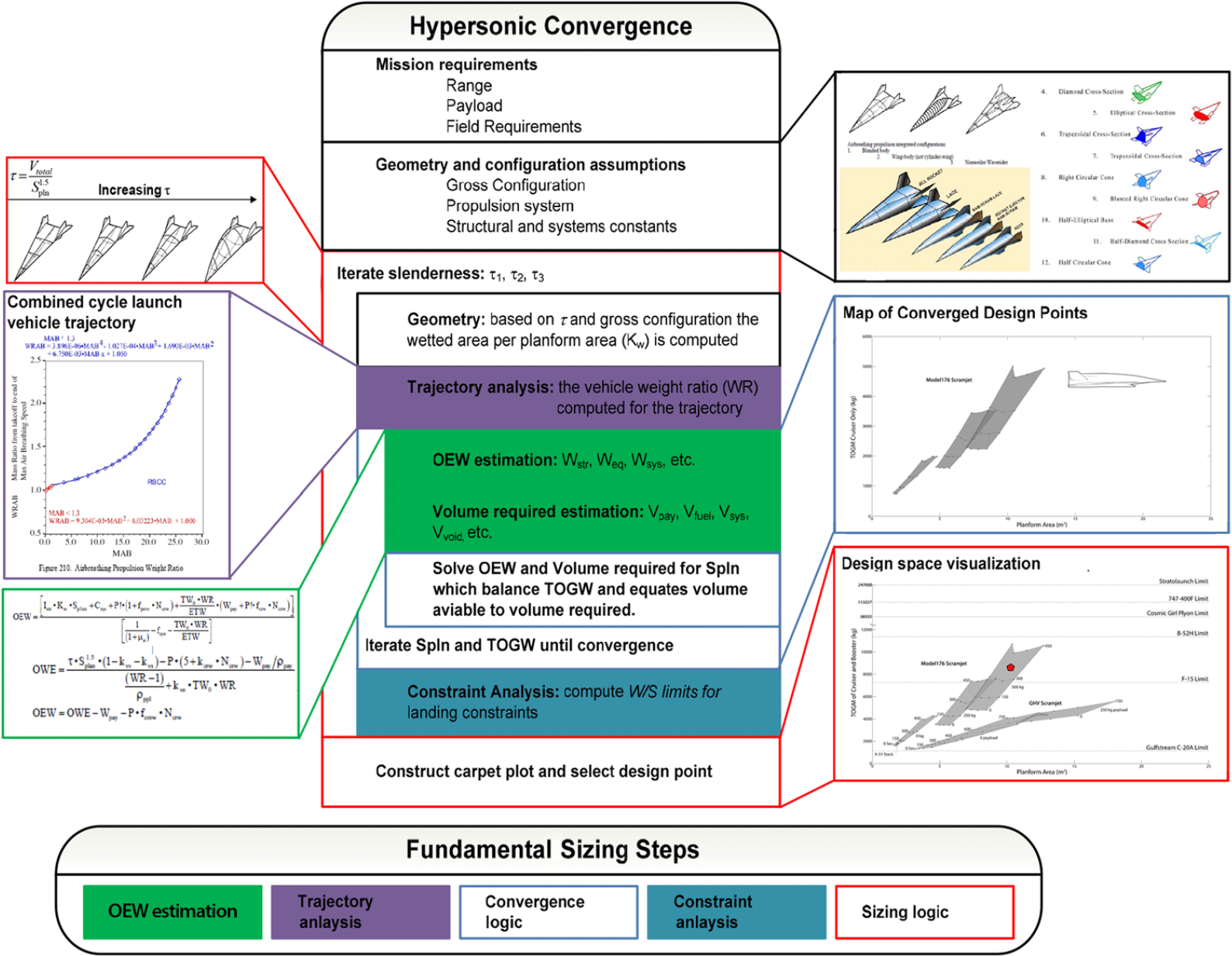
Figure 15. Hypersonic convergence sizing process.
After the discipline module execution sequence, the objective functions are tested for solution convergence. Two objective functions are minimised simultaneously, see Equations (1)-(2) (Reference Gonzalez20,Reference Czysz21,Reference Coleman23) . The first objective function, Equation (1), is a function of operating weight empty by weight analysis ( ${{OW}}{{{E}}_{{W}}}$
) and operating weight empty by volume analysis (
${{OW}}{{{E}}_{{W}}}$
) and operating weight empty by volume analysis ( ${{OW}}{{{E}}_{{V}}}$
). The second objective function, Equation (2), is a function of wing loading (
${{OW}}{{{E}}_{{V}}}$
). The second objective function, Equation (2), is a function of wing loading ( $W/{S_{pln}}$
), planform area (
$W/{S_{pln}}$
), planform area ( ${{{S}}_{{{pln}}}}$
), and take-off gross weight (
${{{S}}_{{{pln}}}}$
), and take-off gross weight ( ${{TOGW}}$
). The convergence process is complete when each cost function equates to zero. In other words, the total vehicle is said to be converged when its solution point is mathematically acceptable because weight and volume converge with
${{TOGW}}$
). The convergence process is complete when each cost function equates to zero. In other words, the total vehicle is said to be converged when its solution point is mathematically acceptable because weight and volume converge with  ${{OW}}{{{E}}_{{W}}} = {{OW}}{{{E}}_{{V}}}$
and
${{OW}}{{{E}}_{{W}}} = {{OW}}{{{E}}_{{V}}}$
and  $ (W/{S_{pln}} ) = TOGW/{S_{pln}}$
. If the objective functions are not satisfied, the planform area and wing loading are iterated and the sequence repeats, until both cost functions are minimised simultaneously. For a more detailed discussion of this process, see Refs. (Reference Gonzalez20,Reference Czysz21).
$ (W/{S_{pln}} ) = TOGW/{S_{pln}}$
. If the objective functions are not satisfied, the planform area and wing loading are iterated and the sequence repeats, until both cost functions are minimised simultaneously. For a more detailed discussion of this process, see Refs. (Reference Gonzalez20,Reference Czysz21).
Objective function 1:
 \begin{equation}{\rm{OWE}}_{\rm{W}} - {\rm{OWE}}_{\rm{W}} = 0 \end{equation}
Objective function 2:
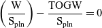 \begin{equation}\left( \frac{\rm{W}}{\rm{S}_{\rm{pln}}} \right) - \frac{\rm{TOGW}}{{\rm{S}}_{\rm{pln}}} = 0 \end{equation}
Each baseline vehicle definition represents a separate synthesis code or CMDS. Each CMDS in turn is generated quickly and consistently by utilising a synthesis system generating software. For more detailed information on this synthesis tool, see Refs. (Reference Rana, McCall, Haley, Gonzalez, Omoragbon, Oza and Chudoba15,Reference Gonzalez20,Reference Omoragbon24).
After solving for each vehicle design point, the locus of vehicle solutions can be mapped onto a solution space plot, where the available solution space is identified within the consideration of both technical and operational constraints. Solution space screening implies an overall focus on visualising multi-disciplinary design interactions and trends, while consistently comparing individual converged minimum-size vehicle point designs with each other.
5.0 RESULTS
This section presents and explores the physical significance of the study results. Results are presented in sequence. The sequence is, first, the consideration of how the synthesis tool has been conditioned for relative accuracy, and, second, a consideration of the sized hypersonic vehicles. The solutions are critically evaluated from the view of  ${{{S}}_{{{pln}}}}$
vs. TOGM. After consideration of the vehicles themselves, the solutions are updated to include the required expendable booster weights where applicable. A consideration of carrier vehicle(s) is included by first examining the carrier vehicle payload capacity. Following the presentation of this material, the geometric properties (combined vehicle and booster length as well as total span) are considered regarding carrier and launch vehicle payload geometric constraints.
${{{S}}_{{{pln}}}}$
vs. TOGM. After consideration of the vehicles themselves, the solutions are updated to include the required expendable booster weights where applicable. A consideration of carrier vehicle(s) is included by first examining the carrier vehicle payload capacity. Following the presentation of this material, the geometric properties (combined vehicle and booster length as well as total span) are considered regarding carrier and launch vehicle payload geometric constraints.
5.1 Toolset calibration
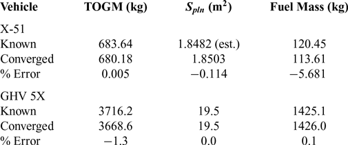
In order to improve tool accuracy, two converged data points, the scramjet adapted Model-176 and the GHV, have been tuned and verified with known vehicle data points. The two known comparable vehicles are the X-51(Reference Mutzman and Murphy25) and the GHV 5X(Reference Ruttle, Stork and Liston14) (see Fig. 9). These points have been converged by adjusting their mission to match the reference vehicle mission as closely as possible. The calibration results are summarised in Table 5. The take-off gross mass, planform area, and fuel mass are compared to illustrate this tool calibration effort. As can be seen, the results are within an acceptable error. The maximum error is 5.7 percent for fuel mass between the Model-176 scramjet baseline configuration and the X-51. The error is likely attributable to either: the scramjet model over-predicting I SP or thrust, or due to underestimating the aerodynamic drag in the aerodynamics model. A possible case also includes a combination of the above phenomena. The now calibrated disciplinary inputs and assumptions are utilised to size the remaining permutations of the hardware, mission, and operation trade matrix.
Table 5. Tool calibration results
5.2 Converged vehicle solution spaces
In order to assist the reader in interpreting the results, Fig. 16 provides detail on what has been plotted and how; the scramjet vehicle results are used in the example. Starting from the top left corner in Fig. 16, each small dot represents a converged vehicle design. Each point plotted corresponds to a different mission cruise time. The cruise time is indicated alphanumerically next to each point. The set of points form the mission cruise time trade for a given payload weight and vehicle shape ( ${\rm{\tau }}$
) (payload weight and vehicle shape are constant for the set of points). Next the results of the trades in vehicle shape, (
${\rm{\tau }}$
) (payload weight and vehicle shape are constant for the set of points). Next the results of the trades in vehicle shape, ( ${\rm{\tau }}$
), are plotted, as illustrated in the top right of Fig. 16. The diagonal lines, highlighted by the callouts for the values of
${\rm{\tau }}$
), are plotted, as illustrated in the top right of Fig. 16. The diagonal lines, highlighted by the callouts for the values of  ${\rm{\tau }}$
, are lines of constant vehicle
${\rm{\tau }}$
, are lines of constant vehicle  ${\rm{\tau }}$
, with the maximum value (minimum slenderness) appearing on the left and the minimum value (maximum slenderness) on the right.
${\rm{\tau }}$
, with the maximum value (minimum slenderness) appearing on the left and the minimum value (maximum slenderness) on the right.
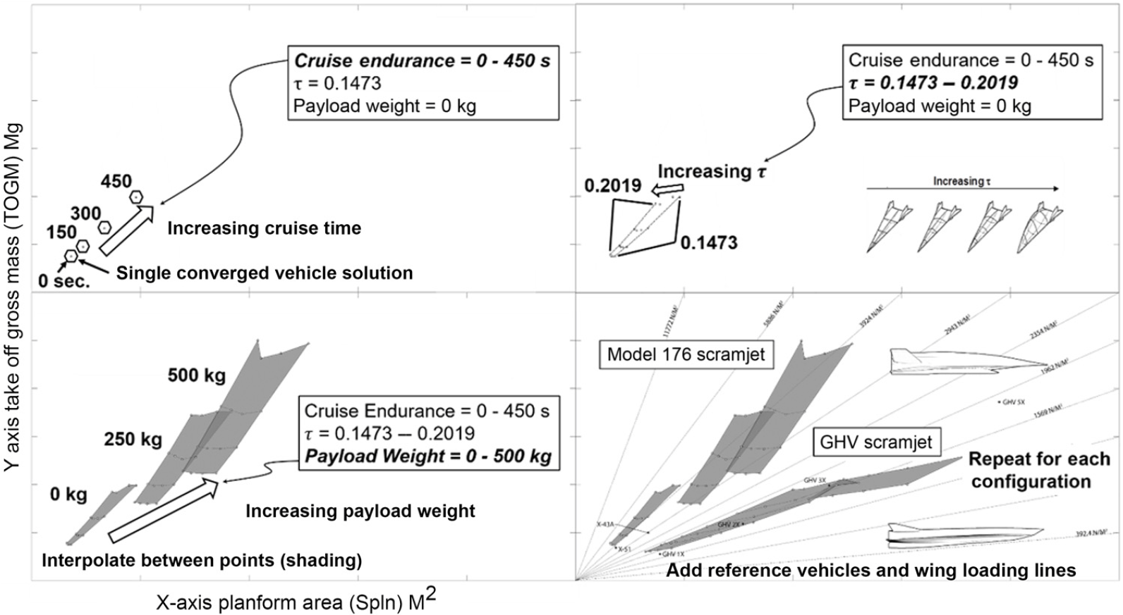
Figure 16. Solution Space Plotting Routine.
Continuing with the bottom left corner of Fig. 16, trades in vehicle payload mass are added to the plot such that three different trades are now captured and illustrated (cruise endurance,  ${\rm{\tau }}$
, and payload weight). Each separate bounded and shaded solution space is for a different payload mass mission of varying cruise endurance and
${\rm{\tau }}$
, and payload weight). Each separate bounded and shaded solution space is for a different payload mass mission of varying cruise endurance and  ${\rm{\tau }}$
. Finally, in the bottom right of Fig. 16, additional vehicle configuration trades are added and any relevant and known reference vehicle is plotted with a corresponding label. Additionally, solid lines are added emanating from the origin outward at various slopes, as lines of constant wing loading. This results figure buildup allows for a graphical comparison of various hardware, mission, and operational trades.
${\rm{\tau }}$
. Finally, in the bottom right of Fig. 16, additional vehicle configuration trades are added and any relevant and known reference vehicle is plotted with a corresponding label. Additionally, solid lines are added emanating from the origin outward at various slopes, as lines of constant wing loading. This results figure buildup allows for a graphical comparison of various hardware, mission, and operational trades.
The results for the air-breathing hypersonic reusable test vehicles are illustrated in Fig. 17. The air-breathing Model-176 results converge for payloads and endurance cruise times of 0-500kg and 0-450seconds, respectively. In contrast, the GHV results converge for the 0kg payload from 0-750seconds of endurance cruise, but do not close for payloads of 250kg and heavier (Fig. 17). If the 250kg results are extrapolated in consideration of the wing loading trend for the 0kg payload case, an idea of the feasible space for larger vehicles becomes apparent. The red line in the figure indicates an approximate wing-loading landing constraint based on the X-24C vehicle study. The X-24C was required to be at or below 71.3lb/ft2 or roughly 3,413N/m2(Reference Combs, Campbell, Cassidy, Sumpter, Seitz, Kachel, James, Walters, Love and Passon12). This landing constraint intersects the Model-176 scramjet vehicles, which implies that without the swing-wing, Model-176 would likely have problems meeting the landing requirements. The GHV derived vehicles are comfortably below the wing loading constraint, except in the case of the RP-1 fueled GHV rocket powered vehicles due to the increased fuel density, see Fig. 18 (these concepts would need to examine wing planform modifications for low-speed flight due to an abort condition).
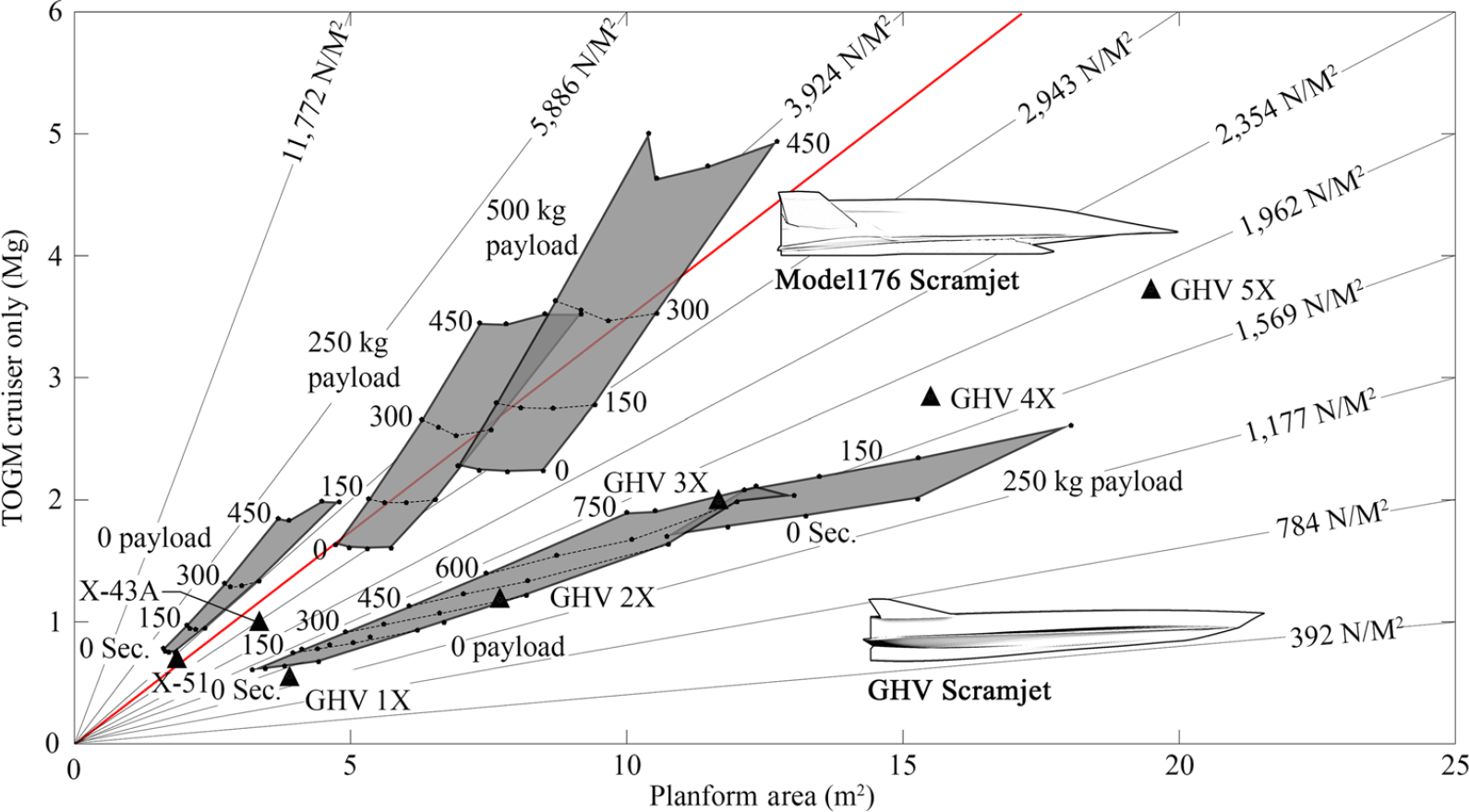
Figure 17. Scramjet powered vehicle solution space.
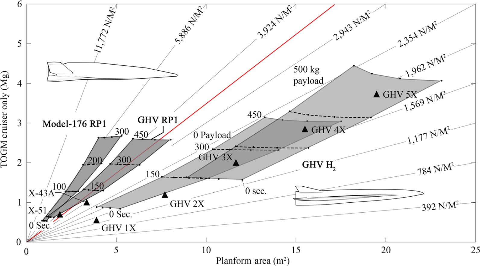
Figure 18. Rocket powered GHV and Model-176 solution space.
The scramjet-powered Model-176 concept solutions follow the 3,924N/m2 wing-loading line. The 5,886N/m2 and 2,943N/m2 lines effectively bracket the solutions. The air-breathing Model-176 solutions do not grow in span as quickly as the GHV solutions. This is due to the volumetrically efficient nature of the all-body and its cross-sectional shape. As a result, all solutions have a planform area under 13m2.
Similarly, the results for the GHV fall in the region of 1,177 to 1,962N/m2. The GHV vehicles grow rapidly with increasing payload and less rapidly with endurance cruise time. This is due to the differences in  ${\rm{\tau }}$
(see Table 4, recall that
${\rm{\tau }}$
(see Table 4, recall that  $\tau = {V_{tot}}/S_{pln}^{1.5}$
) and the GHV scramjet being operated on Ethylene with a higher I SP, yet a lower density than JP-7. The increased I SPand efficiency of the 3D Busemann inlet of the GHV compensates for the lower density fuel, overall accounting for the lower sensitivity to cruise endurance. The GHV’s sensitivity to payload results from low density of the payload compared to the fuel (240kg/m3 vs. 420kg/m3) coupled with overall low volumetric efficiency. The GHV solutions of zero payload mass have a maximum S pln similar to the maximum performance Model-176 solution. Notice that the GHV is the lower mass vehicle for the 0kg payload missions, but for the 250kg missions it slightly exceeds the Model-176 mass. In contrast to the GHV, the Model-176 is less sensitive to payload weight and for the same performance represents a physically smaller vehicle. With its lower volumetric efficiency, the GHV also has more surface area per unit volume. This suggests it will have more technical issues with total heat load compared to a Model-176 vehicle, assuming the fuel is acting as a heat sink for the smaller wetted surface area Model-176. The thin wave rider wing of the GHV at high temperatures will be challenging from a TPS, structural dynamics and manufacturing perspective, although a more detailed investigation is required to quantify these concerns.
$\tau = {V_{tot}}/S_{pln}^{1.5}$
) and the GHV scramjet being operated on Ethylene with a higher I SP, yet a lower density than JP-7. The increased I SPand efficiency of the 3D Busemann inlet of the GHV compensates for the lower density fuel, overall accounting for the lower sensitivity to cruise endurance. The GHV’s sensitivity to payload results from low density of the payload compared to the fuel (240kg/m3 vs. 420kg/m3) coupled with overall low volumetric efficiency. The GHV solutions of zero payload mass have a maximum S pln similar to the maximum performance Model-176 solution. Notice that the GHV is the lower mass vehicle for the 0kg payload missions, but for the 250kg missions it slightly exceeds the Model-176 mass. In contrast to the GHV, the Model-176 is less sensitive to payload weight and for the same performance represents a physically smaller vehicle. With its lower volumetric efficiency, the GHV also has more surface area per unit volume. This suggests it will have more technical issues with total heat load compared to a Model-176 vehicle, assuming the fuel is acting as a heat sink for the smaller wetted surface area Model-176. The thin wave rider wing of the GHV at high temperatures will be challenging from a TPS, structural dynamics and manufacturing perspective, although a more detailed investigation is required to quantify these concerns.
Figure 18 presents the results for the rocket powered GHV and Model-176 configurations. Generally, the geometry configurations align along similar wing loading trends when compared to their scramjet counterparts. Vehicles with the higher density RP-1 are trending higher in wing loading, and the lower density H2 vehicles are trending lower. The kerosene-fueled vehicles are very close in performance, with the GHV configuration trading improved endurance for a physically larger vehicle at the same mass. The hydrogen vehicles are larger at all points for the same performance compared to RP-1 vehicles.
As the GHV is designed with a distinct lifting surface, it appears to outperform the Model-176 in this regime of cruising flight. It is expected, however, that as Mach number or dynamic pressure increases, Model-176 appears to be a better option as the all-body is originally intended for high performance in the reentry regime. Another aspect that could affect the converged size is the specific trajectory performed. An all-body might be better suited to a trajectory utilising the thrust at a higher flight path angle versus the currently investigated trajectory of a constant dynamic pressure lifting climb.
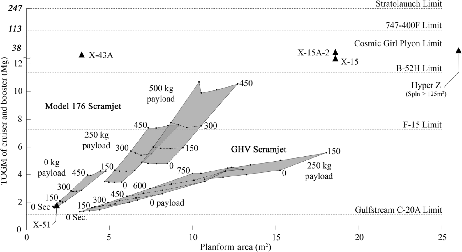
Figure 19. Scramjet powered vehicles with booster weights.
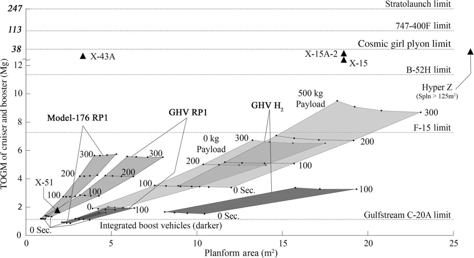
Figure 20. Rocket powered vehicles with booster weights.
5.3 Converged vehicle with booster weight solution spaces
The results for the combined cruiser and booster vehicles are illustrated in Figs. 19 and 20. These figures show the total flight weight for the complete test system as it would be carried for an air-launch. Indicated in the figure are the payload weight limits of several vehicles that could be considered as near term available for an air-launch mission. As the boosters are all sized the same for each vehicle based on TOGM of the cruiser for a fixed boost mission, the shape of the solutions does not change significantly from the previous figures. The added booster more than doubles the mass of each converged cruiser point. The only new converged vehicle points presented in this plot are the rocket vehicles with the modified integrated booster mission. The integrated boost vehicles all trend in a similar fashion compared to the equivalent configuration with an external booster. That is, the integrated boost vehicles are larger in scale, yet lighter overall for the same mission when compared to the external booster stack.
The scramjet-powered vehicle solution space in Fig. 19 shows that all of the investigated points could be carried near term on a B-52H, with only the most demanding Model-176 trades pushing the limits of that carrier vehicle. All of the investigated GHV solutions feasibly could be carried by an F-15 at least in terms of TOGM. As a reminder, these vehicles are all converged to the smallest feasible vehicle for a Mach 6 cruise condition. Any change in mission profile will alter the points, with increases in Mach number causing a significant rise in combined vehicle weight due to added cruiser vehicle performance required, as well as the snowball-effect on external booster weight.
The vertical axis after 12,000kg is non-linear and shows how drastically the payload mass capability of large modern aircraft increases compared to the military underwing hard point limits. The B747-400F limit represents a theoretical maximum if one would utilise the entire payload capability of that vehicle (Cosmic Girl represents the true pylon carry limit for that version of the B747-400). The Stratolaunch carrier is far above all other platform limits, such that it would be difficult to stress the capabilities of such a platform without a plan for significant growth in test vehicle size.
The rocket-powered vehicles with the combined booster weights are presented in Fig. 20. The only new spaces visualised are the integrated boost vehicles representing the darker filled areas. The results show that the integrated boost vehicles are lighter, yet larger than the equivalent externally boosted vehicle. This trend of lighter integrated boost vehicles is not expected to carry over to more demanding Mach numbers and altitudes. This expectation is based on the consideration of excess vehicle size added to satisfy the required performance additions to boost the vehicle to operating conditions; this additional weight would increase dramatically with higher boost conditions and only serve as dead weight during principle mission operation.
The highlighted legacy reference vehicles represent significant contributions in aerospace flight vehicle research, although their weight and size does not directly correspond with research capability or quality, but it does relate to vehicle performance. The X-15 represents a high-performance platform capable of accomplishing many different flight research objectives with margin in payload volume and size for additional experimental equipment. The capability afforded by the X-15 came with the requirement of a modified B-52 launch platform (the NB-52 is no longer in active service). A current carrier and hypersonic research platform is the C-20A/X-60A (the C-20A is slated to be the launch platform for the X-60A). Reviewing the C-20A payload limit in Fig. 20, most studied vehicles exceed this limit. This suggests minimal growth potential of the X-60A on the C-20A launch platform. Additionally, as indicated in Fig. 19, the C-20A carrier vehicle cannot lift any of the reusable scramjet vehicles, even in the minimum case of no cruise time and no payload.
The dimensional solution spaces and geometric carrier constraints are presented in Fig. 21. The general shaded regions in Figs. 19 and 20 translate to the compressed areas in Fig. 21. The observed compression of the solution spaces is due to the now one-dimensional axes units. Figure 21 gives insight into the dimensional limitations of current carrier vehicles given the requirements of potential near-term hypersonic test platforms. Test vehicle span limit for a particular air carrier is determined depending on the mounting location of the test vehicle; for the B-52H with a pylon mount this would be the space between the fuselage and engine pod. The C-20A has a span limit set by the main gear width, and the Falcon 9 has clear fairing size limitations. Length limits are less well defined typically, as vehicles like the Stratolaunch could feasibly mount something as long as or longer than the vehicle itself with the correct CG placement. The length limit of the B-52H is assumed to depend on engine wake that could interfere with the captive vehicle (for the X-24C study, this is dependent on vehicle span and leading-edge angle).
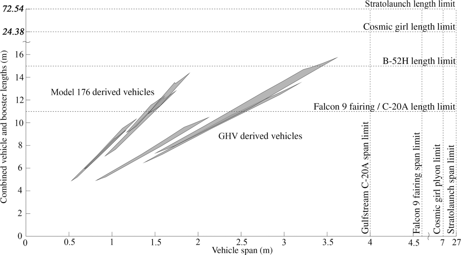
Figure 21. Converged vehicle length and span limits.
The main limitation for the considered vehicles is total length. The Model-176 based vehicles, with the all-body configuration, are less likely to hit span limits as larger growth vehicles are considered as when compared to the GHV, which would approach these limits due to the delta wing. Although the Falcon 9 fairing length limit is included, the vehicles that could be mounted in a Falcon 9 feasibly would not need a booster, and as such, the length would decrease for the vehicles plotted. When considering vertical take-off boosters, a payload fairing may not be required depending on the aerodynamic loads and separation conditions.
6.0 CONCLUSION
A study has been conducted to investigate the available reusable hypersonic test vehicle solution space, while considering current carrier platforms. This study has been executed following a two-prong approach. First, the consideration of past-to-present publicly acknowledged hypersonic test programs and carrier vehicles. Second, the identification of a set of converged hypersonic test vehicle solutions through a synthesis process. The synthesis process has been executed along a hardware, mission, and operation trade matrix. Fundamental elements implemented in the trade study are the hypersonic vehicle configuration (all-body and wing-body), propulsion type (2D/3D scramjet and rocket), and mission elements (endurance cruise time, payload, and accelerator implementation approach). The results are evaluated against known carrier vehicle constraints.
The results indicate that current air-carrier vehicle capability does not support a growth hypersonic test vehicle program without the procurement of modified air-carrier hardware, or the development of a carrier independent test vehicle. The results indicate that a Mach 6 test vehicle of limited payload capacity, both air-breathing and rocket powered, approach the weight limits of standard air-carrier military hardware. For a growth vehicle program or a hypersonic vehicle of mission capability greater than current near-term technology, such as the X-51, the currently employed and near-term available air-carrier hardware is insufficient.
In contrast, launch vehicle capability (vertical launch) is similarly limited (less so in payload capability, but rather, in geometric payload limits). For launch vehicles, fairing size is the primary limiting factor for hypersonic test vehicles (launch vehicle reusability is another entirely separate consideration as well as hardware availability: both are potential limiting factors). If the fairing were to be removed — as in the envisioned case of the X-20 or Dream Chaser — then the fairing would not be a constraining factor.
7.0 FUTURE WORK
The objective of this study has been to gain insight into the limitations of carrier vehicles on hypersonic test vehicle programs. The following expansions to the current work are considered.
• Expanded trade matrix. This study considered a restricted trade matrix. The selected components represent a near-term hardware capability. For the mid-term to long-term period, the trade matrix needs to be expanded accordingly. In particular, the Mach number range is to be increased along with expanded configuration options, operational requirements, and mission profiles and requirements. Of particular interest are vehicles utilising state-of-the-art pre-cooler inlets based on the Reaction Engines research and vehicles utilising combined cycle propulsion.
• Inclusions of pre-chillers for turbojets or combined cycle propulsion also necessitates an investigation of vehicles designed to take-off and land conventionally without a carrier vehicle (single-stage to cruise vehicle), and at what point does this operation make more sense compared to utilising an extremely large (e.g. Stratolaunch) carrier vehicle.
• A more detailed database of vertical launch platforms and their capabilities and limitations. Although the dynamic pressure limitations of launch vehicles are known, it is not known whether a system like a Falcon 9 first stage could be modified or adapted to launch the hypersonic scramjet flight article at higher dynamic pressure conditions and retain reusability. Related to this, it is also desired to size hypersonic vehicles for a sub-orbital or boost-glide trajectory with either integrated reentry manoeuvering systems or an external manoeuvering system that is jettisoned after reentry (like the Hexafly concept(Reference Steelant, Langener, Hannemann, Marini, Serre, Bouchez and Falempin26)).


