

1 Introduction
Quantum electrodynamics (QED) is one of the cornerstones of modern physics. It is considered as the most accurately tested physical theory, thanks to high-precision measurements of quantities such as the anomalous magnetic dipole moment of the electron[Reference Schwinger1, Reference Hanneke, Fogwell and Gabrielse2]. This theory predicts that for large amplitudes of the electromagnetic field, the coupling of photons to the fermionic quantum vacuum plays a major role. This regime of so-called strong-field (SF) QED[3–5] is characterized by effects such as the polarization of vacuum affecting light propagation[Reference Berestetskii, Lifshitz and Pitaevskii6], or the light-induced creation of particle–antiparticle pairs from pure vacuum, a process that can be viewed as the ‘optical breakdown of vacuum’[7–9].
SF QED has been investigated theoretically for almost 100 years, starting with the seminal work of some of the founders of QED[Reference Sauter8, Reference Heisenberg and Euler9]. In striking contrast with the abundance of theoretical results, SF QED has largely remained ‘Terra Incognita’ from an experimental point of view and is thus one of the present frontiers of physics. As a result, most of the theoretical predictions of SF QED have actually never been tested experimentally. The main reason for this situation is the fact that the electromagnetic fields of extreme amplitude required to induce SF QED processes are still experimentally inaccessible.
The interest of generating such extreme fields actually goes far beyond testing theoretical predictions. Laboratory experiments on SF QED will provide a new access to the physics of relativistic quantum plasmas[Reference Di Piazza, Müller, Hatsagortsyan and Keitel4] and physics in extreme conditions[Reference Mourou, Tajima and Bulanov10], two rich scientific fields that are highly relevant for high-energy astrophysical events such as pulsars, magnetars, supernovae and γ-ray bursts[11–13], as well as for the design of future particle colliders[Reference Esberg, Uggerhøj, Dalena and Schulte14]. Looking further ahead, this should ultimately open the way to a new type of ‘particle physics’ experiments where the nonlinear optical properties of the fermionic quantum vacuum will be measured, potentially revealing properties of quantum fields beyond the standard model such as the existence of axions[Reference Mendonça15, Reference Evans and Rafelski16] or millicharged particles[Reference Gies, Jaeckel and Ringwald17].
In this article, we describe a scheme proposed theoretically[18–20] to reach the extreme fields required for the investigation of SF QED, based on the combination of cutting-edge high-power chirped pulse amplification (CPA) lasers and advanced laser–plasma interaction schemes[Reference Vincenti20, Reference Vincenti and Quéré21]. We argue that the experimental resources and knowhow required to implement this scheme are now available, thus making the investigation of SF QED potentially within experimental reach in the coming years.
The outline of this article is the following.
- Section 2 briefly introduces the context, and is mostly intended for newcomers to the topic of SF QED: what are the electromagnetic field amplitudes needed to induce SF QED effects in experiments? Where do we stand now, especially with high-power lasers?
- In Section 3, we present the key paradigm of this article, developed along the years in a series of theoretical works: it relies on the Doppler effect induced on ultraintense laser pulses upon reflection on a curved mirror in relativistic motion. The major experimental challenge is to actually create such a curved mirror and to use it to reflect ultraintense laser beams.
- In Section 4, we argue that among the different schemes of laser–plasma interaction that have been proposed to achieve this goal, the most tractable one consists of using so-called relativistic plasma mirrors, created at the surface of solid targets by high-contrast ultraintense femtosecond laser pulses. We support this statement by summarizing the present physical understanding of these systems, and the state-of-the-art of experiments.
- In Section 5, we specify the intensity gains that relativistic plasma mirrors should be able to induce on femtosecond laser pulses, using a simple model (detailed in Ref. [Reference Vincenti and Quéré21]) that is only summarized here. We explain how the present experimental knowhow makes such experiments realistic and tractable.
- Finally, in Section 6, we discuss some of the key experimental challenges that need to be addressed to implement this scheme and use it to investigate SF QED, as well as some of the possible solutions.
2 Context: the experimental challenges of SF QED
2.1 What are the field values required to investigate SF QED?
The most emblematic manifestation of SF QED is probably the Schwinger effect, also known as the Sauter–Schwinger mechanism[7–9], which predicts that charged particle–antiparticle pairs should spontaneously appear from a vacuum in which a sufficiently strong electric field is applied. We rely on this effect to calculate the order of magnitude of the electric field amplitudes required to investigate SF QED.
The intuitive physical idea underlying this effect is the following. Quantum theory predicts that even the most perfect vacuum has a complex structure, which can be described as a ‘sea’ of so-called virtual particles, with lifetimes δt ≈ ħ/E m (with E m = 2mc 2 the rest mass energy for a massive pair). When an electric field is applied in this vacuum, it provides an energy δW for charged virtual particle pairs during this lifetime, by tearing them apart. If the field is strong enough for δW to exceed the rest mass energy E m, these particles can then turn real, i.e., persist in time rather than recombine. Combining this condition with a layman calculation of δW based on classical mechanics provides the value of the critical field E s required to induce pair creation. The lowest value of E s corresponds to the creation of the lightest known massive charged particles, electrons and positrons (mc 2 = 511 keV ⇒ δt ≈ 10–21 s), and amounts to E s = me 2c 3/eħ = 1.32 × 10¹⁸ V/m: the so-called Schwinger limit[Reference Schwinger7, Reference Sauter8]. This value can of course be derived much more rigorously using the formalism of QED.
Some other SF QED effects require somewhat lower field values, down to a few percent of E s. For example, pair creation in vacuum can occur for lower E-fields when γ-photons are present[Reference Di Piazza, Müller, Hatsagortsyan and Keitel4]: a single of these photons can then provide most of the pair rest mass energy, whereas the strong E-field enables momentum conservation. Another important class of examples corresponds to vacuum polarization effects, the nonlinear propagation of light in vacuum, due to its coupling with fluctuations of the fermionic vacuum, which obviously start occurring well before the optical breakdown of vacuum. Still, these all require truly considerable field values, which largely exceed the electric fields ever generated by mankind, as we now show.
2.2 Where do we stand now?
Major facilities that exploit very large electric fields are particle accelerators: yet, the largest fields generated in the radio-frequency cavities of these accelerators are ‘only’ of the order of 108–109 V/m[Reference Braun, Döbert, Wilson and Wuensch22], far below the Schwinger limit. Nowadays a broad consensus has emerged on the idea that the most promising path to investigate SF QED experimentally rather relies on the use of intense laser beams[Reference Di Piazza, Müller, Hatsagortsyan and Keitel4, 23–30]. The key point is that light energy can be strongly concentrated in space, thanks to focusing, as well as in time, by using ultrashort laser pulses produced by mode locking. As a result, very high light intensities, associated with large E-field amplitudes, can be obtained at the focus of a laser beam even with relatively modest amounts of energy. The intensity of a light beam whose E-field amplitude is the Schwinger limit E s is I s = ε 0cE s2/2 = 4.7 × 1029 W/cm2. Where do present lasers actually stand with respect to this limit?
The peak power of femtosecond (1 fs = 10–15 s) lasers has increased considerably in the recent decades, thanks to the invention of the CPA technique in 1983 by Strickland and Mourou[Reference Strickland and Mourou31], who were awarded the 2018 Nobel Prize in Physics. State-of-the-art CPA lasers reach powers in the petawatt (PW) range[Reference Danson, Haefner, Bromage, Butcher, Chanteloup, Chowdhury, Galvanauskas, Gizzi, Hein, Hillier, Hopps, Kato, Khazanov, Kodama, Korn, Li, Li, Limpert, Ma, Nam, Neely, Papadopoulos, Penman, Qian, Rocca, Shaykin, Siders, Spindloe, Szatmári, Trines, Zhu, Zhu and Zuegel32, 33], by delivering pulses with energies U of tens to hundreds of joules and durations τ of a few tens of femtoseconds. Such powers have become available in tens of laboratories worldwide. These beams typically lie in the near-infrared and can thus be focused down to diffraction-limited areas A in the μm2 range. The maximum intensity that they can deliver is then typically I ≈ U/τA ≈ 1023 W/cm2. Indeed, the highest light intensity ever achieved in the laboratory to date, recently obtained with such a laser, amounts to 5.5 × 10²² W/cm2[Reference Yoon, Jeon, Shin, Lee, Lee, Choi, Kim, Sung and Nam34]. These are already extreme light intensities: starting at 1018 W/cm2, the laser-induced motion of electrons exposed to such beams becomes relativistic in less than 1 fs. Yet, the Schwinger limit I s is still seven orders of magnitude higher than this present record. Further increasing the laser pulse energy can arguably be considered a technologically hopeless path to reach this limit[33] as it would require femtosecond pulses with energies in the range of tens to hundreds of megajoules. Different paradigms are therefore absolutely needed to close this considerable gap.
In the growing scientific community preparing future SF QED experiments, the dominating paradigm consists of colliding such ultraintense laser pulses with a counterpropagating relativistic electron beam[Reference Bula, McDonald, Prebys, Bamber, Boege, Kotseroglou, Melissinos, Meyerhofer, Ragg, Burke, Field, Horton-Smith, Odian, Spencer, Walz, Berridge, Bugg, Shmakov and Weidemann23, Reference Burke, Field, Horton-Smith, Spencer, Walz, Berridge, Bugg, Shmakov, Weidemann, Bula, McDonald, Prebys, Bamber, Boege, Koffas, Kotseroglou, Melissinos, Meyerhofer, Reis and Ragg24, Reference Abramowicz, Altarelli, Aßmann, Behnke, Benhammou, Borysov, Borysova, Brinkmann, Burkart, Büßer, Davidi, Decking, Elkina, Harsh, Hartin, Hartl, Heinemann, Heinzl, TalHod, Hoffmann, Ilderton, King, Levy, List, Maier, Negodin, Perez, Pomerantz, Ringwald, Rödel, Saimpert, Salgado, Sarri, Savoray, Teter, Wing and Zepf29, Reference Reis35]: depending on the beam energy, the laser E-field seen by electrons in their rest frame can be much larger than in the lab frame and, thus, exceed the Schwinger limit E s. Indeed, this was the scheme used in a famous experiment that observed electron–positron pair creation, carried out with the linear electron accelerator at SLAC (USA) in the 1990s, and known as E144[36–38]: by crossing a beam of relativistic electrons (E = 46.6 GeV) with an intense laser pulse (I ≈ 1018 W/cm2), approximately 100 positrons resulting from pair creation by the nonlinear Breit–Wheeler effect (γ-photon + n laser photons → electron–positron pair) were detected.
Yet, as it relies on the initial presence of fermions, this scheme is a priori unsuitable to investigate some of the effects related to the interaction of extreme fields with pure quantum vacuum, one of the most intriguing aspects of SF QED, and in particular the Schwinger effect. From a practical point of view, it is complex and costly as it requires high-accuracy synchronization and overlap of a focused high-power laser with a relativistic electron beam (provided either by a conventional accelerator or by laser–plasma interaction).
The paradigm that we describe in this article can be experimentally less demanding and has the potential to directly induce a nonlinear optical response of the pure quantum vacuum. It consists in considerably increasing the concentration of light energy in time and/or in space. This requires electromagnetic waves of shorter wavelengths, which can be both more tightly focused in space and compressed in time than the near-visible light provided by CPA lasers. This is the idea underlying proposals that rely on X-ray free electron lasers (X-FELs)[Reference Ringwald39] for the quest to the Schwinger limit. However, the typical pulse energy delivered by X-FELs is only in the millijoule range. What is ideally needed is the best of these two types of sources: light pulses with an energy of tens of joules or more, as provided by CPA lasers, but at significantly shorter wavelengths, as provided by X-FELs. The next section explains a general concept that makes it possible to obtain such light beams, starting from the laser pulses already provided by CPA lasers.
3 Boosting ultraintense lasers using curved relativistic mirrors
3.1 General concept
The efficient wavelength down-conversion of a high-power laser pulse is in principle possible by reflecting this pulse on a mirror moving at a velocity v close to the speed of light c: in short, a ‘relativistic mirror’ (RM)[Reference Einstein40]. Upon reflection on such a mirror, the laser pulse gets down-converted at wavelength λ by a factor α ≈ 1/4γ 2 (with γ = (1 – v2/c2)–1/2 the mirror Lorentz factor) and compressed in time by the same factor[Reference Landecker41]. As soon as γ ![]() 3, a femtosecond laser pulse can thus be compressed down to the attosecond time range (1 as = 10–18 s). Assuming perfect reflection, the light beam intensity then gets boosted by 1/α >> 1.
3, a femtosecond laser pulse can thus be compressed down to the attosecond time range (1 as = 10–18 s). Assuming perfect reflection, the light beam intensity then gets boosted by 1/α >> 1.
The diffraction-limited focal spot size of a light beam scales linearly with its wavelength λ. Further gain can therefore be achieved by taking advantage of this wavelength down-conversion to more strongly concentrate the light energy in space. After reflection by an RM, the light can be focused to an area α 2 smaller than the initial laser beam, leading to a gain of 1/α 2 on the light intensity. The combination of these spatial and temporal effects finally results in a total intensity gain that scales as 1/α 3 ∝ γ 6.
These two compression steps can be combined into a single stage, by reflecting the light beam on a ‘curved relativistic mirror’ (CRM)[Reference Bulanov, Esirkepov and Tajima18], as illustrated in Figure 1. Such a CRM simultaneously compresses the pulse in time, down-converts it in wavelength and imprints a wavefront curvature which induces the subsequent focusing of the reflected field. Compared with the use of a flat RM, the major advantage of combining all steps into one is to avoid the considerable technical challenge of manipulating and tightly focusing an intense attosecond beam with traditional optics.
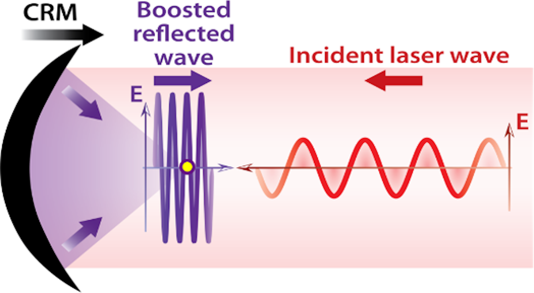
Figure 1 Sketch of principle of a CRM boosting the E-field of a light wave. The yellow dot indicates the CRM focus in vacuum.
Reflecting a PW-class laser beam on a CRM with even a moderate Lorentz factor γ ≈ 10 would thus make the Schwinger limit within experimental reach. Yet, the actual implementation of this approach faces considerable experimental hurdles. How can we generate such RMs, with suitably large γ factor? Can we implement such mirrors on the most powerful lasers to date? In the next section, we present a laser–plasma interaction scheme that is suitable for solving these issues.
3.2 Exploiting ultrahigh-intensity laser–plasma interactions to create RMs
When exposed to a laser beam with I ![]() 1018 W/cm2, electrons are set in relativistic motion[Reference Mourou, Tajima and Bulanov10]. A natural idea is thus to use a first ultraintense laser beam to create an RM by inducing a collective relativistic motion of electrons in a target, and then reflect a second laser beam on this RM[Reference Bulanov, Esirkepov and Tajima18]. Different laser–plasma interaction schemes have been proposed to implement this concept[Reference Bulanov, Esirkepov and Tajima18, Reference Wu, Meyer-ter-Vehn, Fernández and Hegelich42, Reference Tamburini, Di Piazza, Liseykina and Keitel43]. This can, for instance, be achieved by focusing such a laser beam on one side of a very thin foil: electrons from the foil are collectively pushed forward by the laser radiation pressure, thus creating an RM at the rear side of the foil. A second counterpropagating laser beam can, in turn, be reflected from this RM, to be boosted in intensity. Alternatively, the initial paper that introduced the concept of CRM proposed to create these mirrors through the relativistic plasma waves excited in the wake of ultraintense laser pulses propagating in an underdense plasma[Reference Bulanov, Esirkepov and Tajima18].
1018 W/cm2, electrons are set in relativistic motion[Reference Mourou, Tajima and Bulanov10]. A natural idea is thus to use a first ultraintense laser beam to create an RM by inducing a collective relativistic motion of electrons in a target, and then reflect a second laser beam on this RM[Reference Bulanov, Esirkepov and Tajima18]. Different laser–plasma interaction schemes have been proposed to implement this concept[Reference Bulanov, Esirkepov and Tajima18, Reference Wu, Meyer-ter-Vehn, Fernández and Hegelich42, Reference Tamburini, Di Piazza, Liseykina and Keitel43]. This can, for instance, be achieved by focusing such a laser beam on one side of a very thin foil: electrons from the foil are collectively pushed forward by the laser radiation pressure, thus creating an RM at the rear side of the foil. A second counterpropagating laser beam can, in turn, be reflected from this RM, to be boosted in intensity. Alternatively, the initial paper that introduced the concept of CRM proposed to create these mirrors through the relativistic plasma waves excited in the wake of ultraintense laser pulses propagating in an underdense plasma[Reference Bulanov, Esirkepov and Tajima18].
However, because this class of schemes requires two ultraintense laser beams perfectly synchronized in time and overlapped in space, on the femtosecond and micrometre scales, respectively, their experimental implementation proves to be extremely difficult. In this regard, a couple of proof-of-principle experiments have been carried out, but have reported only limited effects on the beam reflected by the RM[44–46], and have not been followed by significant experimental progress for almost a decade.
A much more straightforward scheme is provided by so-called ‘relativistic plasma mirrors’ (p-RMs), created when an ultraintense laser pulse hits a solid target. It has considerable advantages over the previous schemes, in particular:
(i) it relies on a much simpler interaction configuration, where a single ultraintense laser beam both creates the RM and gets reflected by this RM;
(ii) a significant number of experiments with 100-TW-class lasers have demonstrated that these mirrors are highly controllable[47–54] and their physical response to the incident field is very reproducible[53–57];
(iii) it is possible to create curved relativistic plasma mirrors (p-CRMs), such that the reflected beam converges directly to a tight focus[Reference Vincenti20]. This avoids the considerable pitfall of collecting and refocusing the short-wavelength, spectrally broad, intense attosecond pulses.
In the next section, we support these key arguments by briefly summarizing the present state-of-the-art research on relativistic plasma mirrors.
4 Relativistic plasma mirrors
4.1 Basic physics of plasma mirrors
A plasma mirror is a dense plasma created at the surface of a solid target when this target is irradiated and gets ionized by an intense ultrashort laser pulse[58–60]. Owing to its high electron density (few 1023 cm-3, i.e., 102–103 times the critical density n c for the laser frequency), it efficiently reflects the incident laser field. In addition, owing to the ultrashort laser pulse duration, plasma expansion into vacuum is very limited during the interaction. The plasma–vacuum interface therefore remains optically flat for the incident field, i.e., with a density gradient between the plasma and vacuum characterized by a scale length L much smaller than the wavelength λ L of the incident laser field[Reference Kahaly, Monchocé, Vincenti, Dzelzainis, Dromey, Zepf, Martin and Quéré47, Reference Chopineau, Leblanc, Blaclard, Denoeud, Thévenet, Vay, Bonnaud, Martin, Vincenti and Quéré56, Reference Dollar, Cummings, Chvykov, Willingale, Vargas, Yanovsky, Zulick, Maksimchuk, Thomas and Krushelnick61, Reference Rödel, Brügge, Bierbach, Yeung, Hahn, Dromey, Herzer, Fuchs, Galestian Pour, Eckner, Behmke, Cerchez, Jäckel, Hemmers, Toncian, Kaluza, Belyanin, Pretzler, Willi, Pukhov, Zepf and Paulus62]. As a result, plasma mirrors specularly reflect the incident beam, and can be viewed as high-quality mirrors suitable for ultraintense ultrashort laser beams (Figure 2(a))[Reference Thaury, Quéré, Geindre, Levy, Ceccotti, Monot, Bougeard, Réau, d’Oliveira, Audebert, Marjoribanks and Martin63]. This makes them unique systems for advanced applications in ultrahigh-intensity optics[Reference Gordienko, Pukhov, Shorokhov and Baeva19, Reference Vincenti20, 48–50, 64–68].
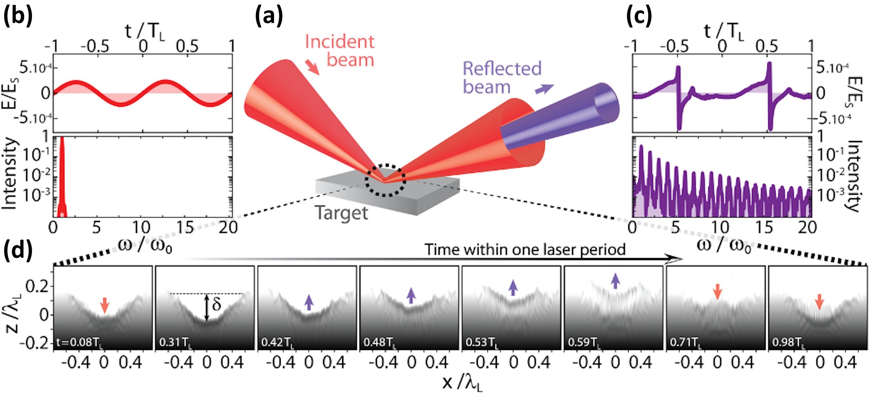
Figure 2 Physics of plasma mirrors. (a) Plasma mirrors specularly reflect an incident ultraintense laser beam. At ultrahigh intensities, this laser field ((b), field E(t) in the upper graph, spectrum in the lower graph) drives a periodic relativistic oscillation of the plasma surface. This induces a Doppler effect on the reflected beam, resulting in a periodically distorted reflected waveform ((c), upper graph), the spectrum of which consists of a comb of high-order harmonics ((c), lower graph). (d) Snapshots of the electron density at the plasma mirror surface (in a Lorentz-boosted frame where the laser is normally incident on the plasma), at different times in a laser optical cycle (see white labels), revealing two key effects: first, the relativistic oscillation of the plasma surface; second, the spatial curvature of this surface induced by the radiation pressure of the incident laser field. From a PIC simulation with a laser intensity I = 1022 W/cm2.
To induce large intensity boosts on the reflected laser beam, plasma mirrors need to be set in relativistic motion, which is possible when they are exposed to laser intensities ranging from at least 1018 W/cm2 up to the highest laser intensities available to date, of a few 1022 W/cm2. The incident laser field then drives a periodic oscillation of the plasma mirror surface, at relativistic velocities (Figure 2). This relativistic oscillating mirror (ROM)Footnote 1 induces a periodic Doppler effect on the reflected field[72–75]. Each time the mirror surface moves outward, it compresses the laser energy in time, leading to a sharpening of the reflected waveform (compare Figures 2(b) and 2(c)). Although still periodic in time, this waveform is no longer sinusoidal: its spectrum thus consists of the combination of the laser frequency ω L with a comb of high-order harmonics of frequencies nω L (Figure 2(c)). This physical process is now fairly well-understood theoretically[Reference Cherednychek and Pukhov36, 69–71, 73–78]. While a complete analytical model is still missing, it can be described with high fidelity by numerical simulations based on the particle-in-cell (PIC) method[79–84].
Plasma mirrors exposed to intense laser pulses can thus provide the type of RM needed to boost the light intensity. Rather than an RM with a uniform velocity, this is an oscillating mirror. As a result, only a part of the incident laser energy will be compressed in time and down-converted in wavelength. This is the price to pay to benefit from the considerable advantages of plasma mirrors, which we have emphasized in the previous section.
One of these advantages is that plasma mirrors are naturally curved (Figure 2(d)): owing to the varying laser intensity across the laser focus, the radiation pressure exerted by the incident laser field induces a curvature of the plasma surface during the interaction[Reference Vincenti, Monchocé, Kahaly, Bonnaud, Martin and Quéré55, Reference Dromey, Adams, Hörlein, Nomura, Rykovanov, Carroll, Foster, Kar, Markey, McKenna, Neely, Geissler, Tsakiris and Zepf85, Reference Wilks, Kruer, Tabak and Langdon86]. This results in focusing of the generated harmonics at typical distances of 10 to 100 μm from the plasma surface[Reference Vincenti20, Reference Vincenti, Monchocé, Kahaly, Bonnaud, Martin and Quéré55, Reference Dromey, Adams, Hörlein, Nomura, Rykovanov, Carroll, Foster, Kar, Markey, McKenna, Neely, Geissler, Tsakiris and Zepf85], thus avoiding the burden of subsequently manipulating and focusing the Doppler-converted beam. This effect has been accurately measured experimentally and modelled analytically[Reference Leblanc, Monchocé, Bourassin-Bouchet, Kahaly and Quéré54, Reference Vincenti, Monchocé, Kahaly, Bonnaud, Martin and Quéré55, Reference Leblanc, Monchocé, Vincenti, Kahaly, Vay and Quéré57].
4.2 Experimental knowhow on relativistic plasma mirrors
In addition to the physical understanding gained on the ROM process over the past 15 years, a considerable knowhow has been developed, mostly from experiments with 100-TW-class lasers. These experiments can be broadly divided into two main generations, presented in the following. This provides a very strong background for a third generation of experiments, where plasma mirrors could be used to boost the intensity of high-power femtosecond lasers.
4.2.1 First-generation experiments (circa 2005→2015)
The very first challenge to address in the investigation of relativistic plasma mirrors was obviously to prove that such mirrors could actually be created in experiments. This implied producing a very dense plasma at the surface of a solid target, with a density gradient between this dense plasma and vacuum of only a fraction of the laser wavelength λ L. As such plasmas expand with typical velocities of a few tens of nanometres/picosecond[Reference Kahaly, Monchocé, Vincenti, Dzelzainis, Dromey, Zepf, Martin and Quéré47, Reference Bocoum, Böhle, Vernier, Jullien, Faure and Lopez-Martens87], the initial solid target must be ionized only in the rising edge of the incident laser pulse, less than a few picoseconds before its maximum. Fulfilling this stringent condition turned out to be very challenging when the peak intensity of the laser pulse is very high (I > 1018 W/cm2). Indeed, the intensity of the comparatively very weak parasite light that precedes these pulses for several nanoseconds (the so-called temporal pedestal, unavoidable with the CPA laser technology[Reference Strickland and Mourou31]), then gets large enough to ionize the target well before the main pulse, and thus initiates plasma expansion. Plasmas created in such conditions have very long density gradient, such that the optical quality of the laser beam is not preserved upon reflection: they are no longer plasma mirrors[Reference Chopineau, Leblanc, Blaclard, Denoeud, Thévenet, Vay, Bonnaud, Martin, Vincenti and Quéré56].
The first generation of experiments on plasma mirrors started when this issue could be solved in a robust way. This was possible by using one or several other plasma mirrors (prior to the final target), exposed to lower laser intensities, as ultrafast high-dynamic optical switches to reduce the temporal pedestal by orders of magnitude[58–60, Reference Lévy, Ceccotti, D’Oliveira, Réau, Perdrix, Quéré, Monot, Bougeard, Lagadec, Martin, Geindre and Audebert88]. Once this issue was solved, high-quality beams comprising tens of harmonic orders could finally be observed in experiments with 100-TW-class lasers (see Figure 3)[Reference Monot, Doumy, Dobosz, Perdrix, D’Oliveira, Quéré, Réau, Martin, Audebert, Gauthier and Geindre37, Reference Thaury, Quéré, Geindre, Levy, Ceccotti, Monot, Bougeard, Réau, d’Oliveira, Audebert, Marjoribanks and Martin63] and even with a 600-fs PW laser[Reference Dromey, Zepf, Gopal, Lancaster, Wei, Krushelnick, Tatarakis, Vakakis, Moustaizis, Kodama, Tampo, Stoeckl, Clarke, Habara, Neely, Karsch and Norreys38, Reference Dromey, Kar, Bellei, Carroll, Clarke, Green, Kneip, Markey, Nagel, Simpson, Willingale, McKenna, Neely, Najmudin, Krushelnick, Norreys and Zepf89]. Different mechanisms of harmonic generation in the reflected beam could be identified[Reference Thaury, Quéré, Geindre, Levy, Ceccotti, Monot, Bougeard, Réau, d’Oliveira, Audebert, Marjoribanks and Martin63, Reference Quéré, Thaury, Monot, Dobosz, Martin, Geindre and Audebert90], including the ROM process, prominent in the interaction regime considered in this article.
The scale length L of the density gradient at the plasma surface has a major influence on the coupling of the plasma with the laser field[Reference Kahaly, Monchocé, Vincenti, Dzelzainis, Dromey, Zepf, Martin and Quéré47, Reference Chopineau, Leblanc, Blaclard, Denoeud, Thévenet, Vay, Bonnaud, Martin, Vincenti and Quéré56]. With the issue of the temporal contrast solved, the accurate control of this parameter in the range of λ L/100 to a few λ L became possible by the intentional introduction of a weak prepulse[Reference Kahaly, Monchocé, Vincenti, Dzelzainis, Dromey, Zepf, Martin and Quéré47, Reference Dollar, Cummings, Chvykov, Willingale, Vargas, Yanovsky, Zulick, Maksimchuk, Thomas and Krushelnick61], which ionizes the target and initiates plasma expansion at an adjustable delay τ ![]() before the main pulse. Thanks to this capability, the efficiency of the ROM process can be optimized, and different physical effects at play can be carefully deciphered (electron ejection[Reference Thévenet, Leblanc, Kahaly, Vincenti, Vernier, Quéré and Faure65], laser-induced curvature of the plasma surface[Reference Vincenti, Monchocé, Kahaly, Bonnaud, Martin and Quéré55, Reference Leblanc, Monchocé, Vincenti, Kahaly, Vay and Quéré57]). More recently[Reference Chopineau, Leblanc, Blaclard, Denoeud, Thévenet, Vay, Bonnaud, Martin, Vincenti and Quéré56], this has enabled identifying the transition from the ‘coherent’ periodic oscillation of the plasma mirror surface (characteristics of the ROM process) to a chaotic dynamic as L is increased up to ≈λ L (beyond which the plasma no longer behaves as a plasma mirror, as in the case of low temporal contrast).
before the main pulse. Thanks to this capability, the efficiency of the ROM process can be optimized, and different physical effects at play can be carefully deciphered (electron ejection[Reference Thévenet, Leblanc, Kahaly, Vincenti, Vernier, Quéré and Faure65], laser-induced curvature of the plasma surface[Reference Vincenti, Monchocé, Kahaly, Bonnaud, Martin and Quéré55, Reference Leblanc, Monchocé, Vincenti, Kahaly, Vay and Quéré57]). More recently[Reference Chopineau, Leblanc, Blaclard, Denoeud, Thévenet, Vay, Bonnaud, Martin, Vincenti and Quéré56], this has enabled identifying the transition from the ‘coherent’ periodic oscillation of the plasma mirror surface (characteristics of the ROM process) to a chaotic dynamic as L is increased up to ≈λ L (beyond which the plasma no longer behaves as a plasma mirror, as in the case of low temporal contrast).

Figure 3 Raw image of an experimental harmonic spectrum (orders ≈10 (left) to 40 (right)) generated upon reflection of the UHI 100 TW laser (CEA Saclay) on a relativistic plasma mirror.
4.2.2 Second-generation experiments (circa 2012→present)
In parallel to these experiments on the physics of plasma mirrors, a second generation of experiments started about 10 years ago, with the goal of controlling and measuring the properties of plasma mirrors and of the attosecond pulses that they generate. Major advances have been achieved along this line in two ways.
- Tailoring the prepulse of the laser beam. When a prepulse beam is used to control the density gradient scale length L, the expansion velocity of the created plasma depends on the local prepulse fluence. Spatially shaping the prepulse fluence profile on target thus results in a spatial modulation of the expansion velocity of the plasma, which in turn leads to the development of a spatial structure of the plasma surface out of the initially flat target surface. This provides a great flexibility for shaping the plasma surface prior to the nonlinear interaction with the main laser beam. It has for instance been used to create optically controlled plasma gratings[Reference Monchocé, Kahaly, Leblanc, Videau, Combis, Réau, Garzella, D’Oliveira, Martin and Quéré49] and holograms[Reference Leblanc, Denoeud, Chopineau, Mennerat, Martin and Quéré64], from which shaped harmonic beams were generated by a subsequent ultraintense pulse. These controllable structured plasma surfaces have also been exploited to fully characterize the amplitude and phase spatial profiles of harmonic beams from plasma mirrors by a ptychographic scheme[Reference Leblanc, Monchocé, Bourassin-Bouchet, Kahaly and Quéré54, Reference Leblanc, Monchocé, Vincenti, Kahaly, Vay and Quéré57]. In the ROM regime, these measurements have provided clear evidence for the wavefront curvature imprinted on the harmonic beam by the surface denting induced by radiation pressure, which should lead to focusing of this beam at a short distance after the plasma mirror.
- Tailoring the main ultraintense driving laser field. During the interaction of a plasma mirror with an ultraintense laser pulse, the plasma dynamics is dominated by the collective ‘coherent’ motion of a large ensemble of electrons, directly driven by the laser fields E(r,t) and B(r,t). This dynamics is thus controllable by tailoring the driving laser field in time, space or space–time. Such a control has been demonstrated in a number of experiments, which have for instance enabled the generation of isolated attosecond pulses from plasma mirrors using laser fields with ultrafast wavefront rotation (attosecond lighthouse effect)[Reference Wheeler, Borot, Monchocé, Vincenti, Ricci, Malvache, Lopez-Martens and Quéré48], the enhancement of the harmonic generation efficiency by sub-laser-cycle temporal shaping of the driving laser field[Reference Yeung, Rykovanov, Bierbach, Li, Eckner, Kuschel, Woldegeorgis, Rödel, Sävert, Paulus, Coughlan, Dromey and Zepf51] or the generation of harmonic vortex beams carrying orbital angular momentum[Reference Denoeud, Chopineau, Leblanc and Quéré50]. Very recently, spatiotemporally shaped laser fields have been used to implement a new measurement technique called dynamical ptychography, which has enabled the first accurate temporal characterization of attosecond pulses generated from plasma mirrors[Reference Chopineau, Denoeud, Leblanc, Porat, Martin, Vincenti and Quéré53]. This has provided clear evidence for the generation of Fourier-transform-limited attosecond XUV pulses through the ROM mechanism (Figure 4).

Figure 4 Measured temporal intensity profile of the attosecond pulses produced by the ROM mechanism (superposition of harmonic orders 9 to 14). From Ref. [Reference Chopineau, Denoeud, Leblanc, Porat, Martin, Vincenti and Quéré53].
5 Intensity boosting using relativistic plasma mirrors
Intensity boosting using p-CRM was first studied analytically 17 years ago[Reference Gordienko, Pukhov, Shorokhov and Baeva19], assuming plasma mirrors created on ideally curved pre-shaped solid targets. At the time, it was believed that the harmonic spectra generated from plasma mirrors follow a universal power-law decay, as n –p, where 5/2 < p < 3[Reference Gordienko, Pukhov, Shorokhov and Baeva77] and n is the harmonic order. As shown in Ref. [Reference Vincenti20] and further supported by the analysis provided in this section, achieving extreme intensities close to the Schwinger limit with such a fast spectral decay requires focusing of thousands of harmonic orders down to their diffraction limit. In this regard, Solodov et al. [Reference Solodov, Malkin and Fisch91] argued that fulfilling this requirement is not feasible due to unavoidable laser and/or plasma imperfections, and concluded that the maximum intensities achieved with the scheme proposed in Ref. [Reference Gordienko, Pukhov, Shorokhov and Baeva19], would actually be limited to 1023–1024 W/cm2 at most in practice.
Since this initial work, multiple theoretical/numerical studies[Reference an der Brügge and Pukhov69, Reference Edwards and Mikhailova71, Reference Gonoskov, Korzhimanov, Kim, Marklund and Sergeev75] have shown that the harmonic power law decay with 5/2 < p < 3 is actually not universal, but rather restricted to specific interaction conditions. These studies also demonstrated that much more favourable shapes of the harmonic spectra can be produced, for instance by optimizing the bulk plasma density at the target surface. Leveraging on these advances, the idea of using p-CRM to boost the intensity of ultraintense lasers has recently been revived and carefully validated theoretically employing the very first 3D PIC simulations of plasma mirror focusing[Reference Vincenti20]. Equally important, Ref. [Reference Vincenti20] also proposed a more tractable all-optical scheme to curve the plasma mirror surface in experiments (starting from an initially flat solid target), achievable with the experimental knowhow acquired during the first generation of plasma mirror experiments. Using cutting-edge spatiotemporal measurements of a PW laser pulse[Reference Pariente, Gallet, Borot, Gobert and Quéré92, Reference Jeandet, Borot, Nakamura, Jolly, Gonsalves, Tóth, Mao, Leemans and Quéré93] and realistic plasma density profiles (i.e., a finite density gradient at the plasma surface) as inputs in PIC simulations, this scheme was shown to be robust against potential experimental imperfections. One of the main reasons for this robustness is that in these optimal laser–plasma interaction conditions, the focusing of a few tens of harmonic orders is sufficient to reach extreme intensities, against thousands in non-optimal conditions.
In the following section, we first provide a brief theoretical analysis of the scheme introduced in Ref. [Reference Vincenti20] and illustrated in Figure 5. This is based on a theoretical model of harmonic focusing by a curved relativistic plasma mirror that will be detailed in a separate publication[Reference Vincenti and Quéré21]. We then use this analysis to estimate the peak intensities that could be achieved by applying this scheme to state-of-the-art high-power CPA lasers.

Figure 5 Principle of intensity boosting using a p-CRM. The plasma surface curvature is induced either by radiation pressure, or by more demanding schemes such as preshaped solid targets (e.g., micro-off-axis parabolas).
5.1 Analysis of the physical scheme
Let Ê(ω) be the spectrum of the distorted waveform field E(t) reflected by the relativistic plasma mirror. In order to derive simple scaling lawsFootnote 2, we consider that the spectral intensity S n = |Ê(ω = nω L)|2 can be described by the power-law decay S n = |Ê L|2 n –α, from harmonic order n = 1 (fundamental frequency, with spectral intensity |Ê L|2), up to n = n m (spectral cut-off of the harmonic spectrum beyond which the signal exponentially decreases). Recent extensive numerical studies have shown that this analytical form constitutes a rather satisfactory model of harmonic spectra, with α varying from approximately 1.3 (optimized generation → slow spectral decay) to approximately 8 (unoptimized generation → fast spectral decay), depending on the interaction conditions (laser intensity, incidence angle, gradient scale length L)[Reference Edwards and Mikhailova71]. In this model, the parameter α determines the conversion efficiency from the laser frequency into the harmonics, which is crucial for intensity boosting. We also consider that all harmonics are in phase, such that their superposition in time forms Fourier-transform-limited attosecond pulses: an assumption supported by numerical simulations, and confirmed by recent temporal measurements[Reference Chopineau, Denoeud, Leblanc, Porat, Martin, Vincenti and Quéré53].
The key idea is to use curved plasma mirrors to directly focus the reflected field at a short distance in front of the plasma surface, without any prior spectral filtering (Figure 5). We characterize such a curved mirror by a parameter δ, which is the depth difference between the edge of the laser focal spot and its centre (see Figure 2(d)). Controlling δ to optimize the focusing of the reflected beam is a major aspect of this scheme.
Such a p-CRM induces a wavefront curvature on all frequencies of the reflected beam, but the consequences on the subsequent propagation depend on the wavelength, with a gradual transition between two regimes: (i) the longest wavelengths (lowest harmonic orders), i.e., those such that λ >> δ, are hardly affected (Figure 5, red reflected beam), so that they form a collimated beam over the Rayleigh length, and then diffract; (ii) in contrast, harmonic components such that λ << δ get focused, and in the absence of geometric aberrations, converge to a focal spot area A ∝ λ 2 = (λ L/n)2 that gets smaller as harmonic order increases (Figure 5, purple beam). This chromatic nature of the focusing has two major consequences.
• Spectral rectification and temporal compression at focus. Because higher harmonic orders are more tightly focused, the harmonic spectrum gets ‘rectified’ at the focus of the p-CRM (Figure 4). Owing to 1/n 2 scaling of the focal area, it now becomes S n=|Ê L|2 n (2 – α) right at focus (instead of S n = |Ê L|2 n –α), up to the spectral cut-off n = n m. Numerical simulations indicate that using plasma mirrors in optimized interaction conditions with a laser intensity I
 1020 W/cm2, one can achieve α ≤ 2: high harmonic orders then dominate the spectral content of the field at the p-CRM focus. The width of the spectrum gets strongly enhanced at focus, resulting in the localFootnote 3 generation of much shorter attosecond pulses, and hence in a reinforced intensity boost. The spectral rectification effect occurring between the p-CRM surface and its focus is clearly observed in the simulation results of Figure 6(a). This rectification is responsible for the striking difference between the field waveforms E(t) calculated right after reflection (Figure 6(c)) and at the p-CRM focus (Figure 6(d)).
• Formation of a high-intensity low-frequency light shell. The long wavelengths that are only weakly affected by the p-CRM curvature co-propagate with the converging beam of high-order harmonics, remaining quasi-collimated for tens to hundreds of micrometres. When α
2, they only moderately contribute to the total field intensity at focus. As is explained later, they still play an important role for the experimental use of this scheme for the investigation of SF-QED effects in pure vacuum, by forming a high-intensity low-frequency ‘protective light shell’ around the p-CRM focus that should prevent residual particles in the vacuum from reaching the area with the highest light intensities[Reference Vincenti20].

Figure 6 (a) Spectral and (b)–(d) temporal effects of the reflection of an ultraintense laser field on a p-CRM, from PIC simulations. The spectral rectification effect is highlighted in (a), by comparing the harmonic spectrum right after the p-CRM (black) and at the p-CRM focus (red). (b)–(d) Comparison of the waveforms of the incident field (b), of the field right after reflection from the p-CRM (c) and of the field right at the centre of the p-CRM focus (d). The strong difference between (c) and (d) is due to the spectral rectification effect evidenced in (a). All fields are plotted in units of the Schwinger field E s, and the intensity of the incident laser is I = 1022 W/cm2.
Based on this model and using a few simplified approximations supported by numerical simulations, it can be shown[Reference Vincenti and Quéré21] that the total intensity gain Γ at the focus of the p-CRM, with respect to the intensity of the laser beam on the plasma mirror, can be written as the product of three terms:

where η 0 is the reflectivity of the plasma mirror for the laser wavelength, and typically lies between 0.5 and 0.8[Reference Chopineau, Leblanc, Blaclard, Denoeud, Thévenet, Vay, Bonnaud, Martin, Vincenti and Quéré56, Reference Thaury, Quéré, Geindre, Levy, Ceccotti, Monot, Bougeard, Réau, d’Oliveira, Audebert, Marjoribanks and Martin63, Reference Hörlein, Dromey, Adams, Nomura, Kar, Markey, Foster, Neely, Krausz and Tsakiris94, Reference Tsai, Arefiev, Shaw, Stark, Wang, Zgadzaj and Downer95]. The second term accounts for the global spatial effect of the focusing induced by the p-CRM, and already leads to significant gain. For instance, when δ ≈ λ L, it amounts to (4π)2 ≈ 160. The last term in Equation (1) is undoubtedly the most important and is characteristic of the coherent temporal beating of n m harmonic frequencies. It accounts for the spatiotemporal effect of focusing: the superposition of harmonics up to order n m forms attosecond bunches of light, which are shorter (and, hence, more intense) at the p-CRM focus owing to the spectral rectification effect induced by focusing. This is the effect that has been called ‘coherent harmonic focusing’ in Ref. [Reference Gordienko, Pukhov, Shorokhov and Baeva19].
To illustrate the consequences of Equation (1), we consider the case α = 2, which is predicted to be achievable in optimized interaction conditions. The harmonic spectrum at focus is then flat up to n m and, thus,  ${\left(\sum_{n=1}^{n_{\rm m}}{n}^{1-\frac{\alpha }{2}}\right)}^2={n}_{\rm m}^2$. For a spectral cut-off n m = 40, this factor amounts to n m2 = 1600, leading to a total gain Γ of the order of 105 if δ ≈ λ L. This shows that this intensity boosting scheme does not call for the generation of very high harmonic orders, as envisioned in the first theoretical proposal[Reference Gordienko, Pukhov, Shorokhov and Baeva19], but only requires a modest comb of a few tens of harmonic orders. As emphasized earlier, harmonic combs with such a spectral content are already generated with 100-TW-class lasers (see Figure 3). In these conditions, the consequences in the time domain of spectral rectification and coherent harmonic focusing are very striking, as shown in Figure 6(d). Only a modest enhancement of the field amplitude is observed right after reflection on the p-CRM (compare Figures 6(b) and 6(c)): it is solely due to the temporal compression induced by the Doppler effect. In contrast, a considerable field enhancement is observed at the centre of the p-CRM focus (compare Figures 6(b) and 6(d)). The waveform at this position consists of a train of attosecond spikes, although no spectral filtering has been applied: this is a consequence of the spectral rectification effect at focus.
5.2 Estimation of achievable light intensities
According to the analysis of the previous section, the conditions to be fulfilled to obtain large intensity boosts from p-CRM and thus achieve intensities totally out of reach of present laser technology are:
(i) to optimize the efficiency of high-order harmonic generation to obtain a slow spectral decay (i.e., α
2 in the framework of the power-law model), up to at least a few tens of harmonic orders;(ii) to produce p-CRM of high surface shape quality (→negligible geometric aberrations) with a depth δ of at least a fraction of λ L, to ensure the focusing of the harmonics (the tighter the focusing, the higher the intensity gain).
The knowhow required to fulfil condition (i) is provided by the first generation of experiments on plasma mirrors. The concepts developed in the second generation to both control and measure the spatiotemporal properties of the reflected beam, down to the attosecond time scale, provide a strong basis to experimentally tackle condition (ii).
What are the light intensities that we can aim at by applying relativistic plasma mirrors to terawatt (TW) and PW CPA lasers? This is specified in Figure 7, obtained from the combination of the previous analytical model with numerical simulations. These numerical simulations are required here, in particular, to estimate the values of α that best account for the harmonic spectrum decay at different laser intensities. The achieved intensity gain Γ (ratio of black or red curve to the grey curve) increases with laser power because the p-CRM can be driven more efficiently with more powerful lasers.

Figure 7 Light intensity as a function of peak power P of the driving laser. Grey curve: maximum intensity achievable from the laser itself. Black curve: with intensity boost, curvature of the p-CRM induced by radiation pressure. Red curve: optimized curvature leading to focusing of the harmonics at their diffraction limit. The red star indicates the present intensity record achieved with a 4 PW laser[Reference Yoon, Jeon, Shin, Lee, Lee, Choi, Kim, Sung and Nam34]. The different grey areas indicate the estimated ranges of light intensities that could be reached, depending on the class of power of the lasers used to irradiate relativistic plasma mirrors.
We consider two scenarios. The first corresponds to the case where one exploits the curvature of plasma mirrors induced by radiation pressure. This curvature ‘comes for free’ in the interaction with plasma mirrors, but is only weakly controllable and cannot be arbitrarily increased to induce a very tight focusing of the harmonics. Yet, using this scheme one can already aim at gains Γ 1 ≈ 103, resulting in intensities of 1023 W/cm2 on 100-TW-class lasers, i.e., higher than the present intensity world record[Reference Yoon, Jeon, Shin, Lee, Lee, Choi, Kim, Sung and Nam34], and ![]() 1025 W/cm2 with PW-class lasers[Reference Vincenti20], already sufficient to induce clearly observable SF QED effects.
1025 W/cm2 with PW-class lasers[Reference Vincenti20], already sufficient to induce clearly observable SF QED effects.
The upper curve corresponds to the truly optimal limit of our intensity boosting scheme, where harmonics are focused down to their diffraction limit (spot size ≈ λ L/n). This requires using p-CRM with a larger curvature, and hence larger depth δ (typically δ ≈ λ L= 800 nm). The experimental challenge is to create relativistic plasma mirrors with such curvatures, while avoiding spatial aberrations. If successfully implemented on the most powerful lasers available nowadays, this would lead to intensity gains of Γ 2 ≈ 106, resulting in intensities of a few 1028 W/cm2, approaching the Schwinger limit.
The intensity value that can actually been reached experimentally between these two extremes will essentially depend on how tightly one manages to focus the beam reflected by the p-CRM (depending, e.g., on spatial aberrations of the p-CRM), and on the peak power of the most powerful laser on which this scheme can be implemented.
Despite the theoretical and experimental advances described in the previous section, relativistic plasma mirrors have not yet been used experimentally to boost the intensity of ultraintense lasers. Indeed, inducing and measuring large intensity boosts on high-power lasers using this scheme still requires solving considerable experimental challenges. Its use for the investigation of SF QED effects in pure vacuum (such as the Schwinger effect) also faces potential impediments. These are discussed in the last section of this paper.
6 Challenges and open questions
Reaching the light intensities required to investigate SF QED without resorting to collisions with relativistic particle beams will require solving several experimental challenges. In this last section, we provide our own view of the main issues, and potential directions to solve them.
6.1 Interaction of PW lasers with relativistic plasma mirrors
To achieve the intensities required for experiments on SF QED, one will need to start from the highest light intensities already available, i.e., to use PW-class lasers. The first challenge is thus to master the interaction of relativistic plasma mirrors with PW lasers. Only few experiments have been carried out at this power level so far[Reference Dromey, Zepf, Gopal, Lancaster, Wei, Krushelnick, Tatarakis, Vakakis, Moustaizis, Kodama, Tampo, Stoeckl, Clarke, Habara, Neely, Karsch and Norreys38, Reference Dromey, Kar, Bellei, Carroll, Clarke, Green, Kneip, Markey, Nagel, Simpson, Willingale, McKenna, Neely, Najmudin, Krushelnick, Norreys and Zepf89], with laser pulse durations that were most likely too long for the application envisioned here.
Such experiments call for PW lasers with ultrahigh temporal contrasts, suitable to create relativistic plasma mirrors on solid targets. In practice, reaching the required temporal contrast has so far only been possible by using plasma mirrors as high-dynamic ultrafast optical switches after the optical compressor. This is required, in particular, to eliminate the picosecond temporal pedestal resulting from compression defects induced in the compressor, which is typically strong enough to ionize the target before the main laser.
At present, only a few of the existing PW lasers are equipped with such a device. The scientific perspectives opened by the application of relativistic plasma mirrors to PW lasers should be a strong incentive for PW facilities to get equipped with single or double plasma mirrors contrast improvement systems, so that intensity boosting using relativistic plasma mirrors becomes possible.
6.2 Controlling and optimizing the curvature of relativistic plasma mirrors
A second challenge will be to control and optimize the surface curvature of relativistic plasma mirrors, to induce a tight focusing of the reflected beam (consisting of the fundamental laser frequency and all generated harmonics), ideally up to the diffraction limit. The natural curvature induced by radiation pressure is predicted to lead to significant intensity gains[Reference Vincenti20] and could already be exploited in the lab. However, it is far from sufficient to approach the Schwinger limit, even with the most powerful lasers available to date. To this end, more strongly curved plasma surfaces are required.
Such conditions could for instance be fulfilled by creating the plasma mirrors on pre-shaped solid targets, in the form of micro-off-axis parabolas. Another more flexible solution could consist in optically shaping the plasma surface prior to the interaction with the main ultraintense beam. As suggested by the experiments described in Refs. [Reference Monchocé, Kahaly, Leblanc, Videau, Combis, Réau, Garzella, D’Oliveira, Martin and Quéré49, Reference Leblanc, Monchocé, Bourassin-Bouchet, Kahaly and Quéré54, Reference Leblanc, Monchocé, Vincenti, Kahaly, Vay and Quéré57, Reference Leblanc, Denoeud, Chopineau, Mennerat, Martin and Quéré64] creating a concave plasma surface of adjustable curvature is in principle possible by ionizing the target surface with a prepulse beam having a donut-shape spatial intensity profile (e.g., a Laguerre–Gaussian beam).
6.3 Estimating the peak intensity at the plasma mirror focus
A third challenge will be to determine, or at least estimate, the peak intensity achieved at the focus of the p-CRM. A standard approach to determine the intensity of a light pulse consists in measuring its temporal duration τ, focal area A and energy U, and then uses I ≈ U/τA. Advanced spatial and temporal measurement techniques are now available for harmonics generated from plasma mirrors, which would in principle make it possible to estimate τ and A. The energy U would then be the last parameter remaining to be determined.
In the case of high-order harmonic generation in gases, U is traditionally determined by using calibrated XUV diodes[Reference Stuik, Scholze, Tümmler and Bijkerk96] to measure the energy of one or a few harmonics, selected using spectral filtering. This technique has also been implemented on harmonic beams generated from plasma mirrors with 100-TW-class lasers[Reference Hörlein, Nomura, Osterhoff, Major, Karsch, Krausz and Tsakiris97]. Yet, we argue that this not a suitable approach to estimate the peak intensity at the focus of the p-CRM, for two main reasons. First, the accumulation of uncertainties on the multiple parameters determining I can lead to considerable errors. This is particularly the case for the energy U, especially when measurements must be performed in the harsh radiative environment of laser–plasma experiments. Second, this approach always provides the energy in a limited spectral interval, while what would really be needed here is the energy for all harmonic orders up to the spectral cut-off.
A different approach is clearly required. The accurate measurement of high laser intensities (![]() 1016 W/cm2) is actually still an unsolved problem, which has resisted all efforts of the ultrahigh-intensity research community for more than 25 years[Reference He, Longman, Pérez-Hernández, de Marco, Salgado, Zeraouli, Gatti, Roso, Fedosejevs and Hill98]. Yet, for initial experiments on SF QED a reasonable initial goal would be to estimate an order of magnitude of the light intensity, and to prove that large boosts are induced, not to accurately determine an intensity value. This significantly simplifies the problem.
1016 W/cm2) is actually still an unsolved problem, which has resisted all efforts of the ultrahigh-intensity research community for more than 25 years[Reference He, Longman, Pérez-Hernández, de Marco, Salgado, Zeraouli, Gatti, Roso, Fedosejevs and Hill98]. Yet, for initial experiments on SF QED a reasonable initial goal would be to estimate an order of magnitude of the light intensity, and to prove that large boosts are induced, not to accurately determine an intensity value. This significantly simplifies the problem.
We argue that for such an objective, a suitable approach would be to measure the products of the interaction of the beam at the p-CRM focus with a secondary target. Measuring, e.g., the directional ion beams produced from such an interaction, one would be able to obtain an order-of-magnitude estimate, maybe even an accurate value, of the peak intensity of the boosted beam, through comparison of the measured particle energy spectra with the predictions of PIC simulations. Although experimentally challenging given the short distance between the p-CRM surface and its focus, implementing such an interaction is clearly feasible.
6.4 Effect of residual particles in the focal volume of the boosted beam
Detecting SF QED effects such as pair creation by the Schwinger mechanism ideally requires the boosted field to propagate in a pure vacuum, i.e., such that the number of pre-existing particles along its path is significantly lower than the number of created Schwinger pairs. If not, the QED cascades[Reference Bell and Kirk99, Reference Grismayer, Vranic, Martins, Fonseca and Silva100] initiated by pre-existing particles might dominate. A key point is thus to ensure that the number of particles in the focal volume of the boosted field can be made negligible. As this focal volume is very small (≈10–21 to 10–17 m3), the average number of background particles originating from residual gas in the vacuum chamber will be low (<<1) at the typical pressure of 10–6–10–5 mbar (1 mbar = 100 Pa) used in these experiments.
However, the boosted field will be focused at only tens to hundreds of micrometres away[Reference Vincenti20] from the dense plasma forming the p-CRM. Energetic particles originating from this dense plasma could be a major issue. This is where the longest wavelengths contained in the reflected beam should play a major role: through the ponderomotive force, they form a micrometre-scale protective shell around the submicrometre focus where the highest intensities are reached[Reference Vincenti20]. This ponderomotive ‘snow-plow’ effect could enable the interaction of the most intense part of the beam with pure quantum vacuum. We note that clear experimental and numerical evidence for the efficient ejection of relativistic electrons out of the focal volume of an ultraintense laser beam reflected by a plasma mirror has already been obtained[Reference Thévenet, Leblanc, Kahaly, Vincenti, Vernier, Quéré and Faure66].
The PIC simulations needed to quantitatively investigate this point require computing the interaction from the p-CRM surface to its focus in a 3D geometry with very high spatial resolution (owing to the presence of high-order harmonics). Although this is beyond the reach of present computing resources, such simulations should become tractable in the coming years with the advent of exascale supercomputers. Still, given the extreme complexity of the problem, a reliable and accurate answer to this issue definitely calls for experiments under real conditions. In case some particles coming from p-CRM are still present in the focal volume of the boosted beam, the next question will be: can the particles originating from the SF QED processes initiated by these pre-existing particles be discriminated from those created through the interaction of the beam with the quantum vacuum, for instance through their energy spectrum or angular distribution?
In conclusion, in this article we have recalled the basis of a promising idea to reach the intensities required for the experimental investigation of SF QED, potentially up to the Schwinger limit, using the state-of-the-art CPA laser technology and laser–plasma interaction. Our key argument is that all the conditions are now met to tackle this great experimental challenge. We have provided our view on the main issues that need to be addressed, and have suggested possible directions to do so.
Acknowledgement
F.Q. acknowledges financial support from the European Research Council (ERC Grant Agreement No. 694596). An award of computer time was provided by the INCITE program (project ’PlasmInSilico’). This research used resources of the Argonne Leadership Computing Facility, which is a DOE Office of Science User Facility supported under Contract No. DE-AC02-06CH11357. This work was supported by the French National Research Agency (ANR) T-ERC program (Grant No. ANR-18-ERC2-0002). We acknowledge the financial support of the Cross-Disciplinary Program on Numerical Simulation of CEA, the French Alternative Energies and Atomic Energy Commission. The authors are grateful to Luca Fedeli, Adrien Leblanc Antonin Sainte-Marie, Philippe Martin and Neil Zaïm for stimulating discussions on the topic of the article. We also wish to thank Adrien Leblanc for his great support in the elaboration of Figures 1, 2 and 5.


 Open access