


Introduction
Owing to the release of ultra wideband (UWB) spectrum of 3.1–10.6 GHz for unlicensed use by the Federal Communications Commission in February 2002 [Reference Hall and Hao1], a lot of attention has been given to applications of UWB technology. Among these applications, body-centric wireless communications involve wireless body area networks (WBANs), which is one of the major areas. It requires devices to communicate off-, on-, and in-body. Significant progress in WBANs has led to rapid development of UWB antennas for wearable applications in sports, military equipment, and other biomedical engineering.
Hence, advancements in research get considerable attention in the dominion of biotelemetry. Biotelemetry is making remarkable footprints because of the people’s fast moving lifestyle. Many of the people become vulnerable to fatal diseases as they avoid or skip regular checkups because of their lifestyle. So reactive health management signs off from its importance where proactive health management raises its hands. This proactive health management paves way in early detection of health issues especially for people in military, sports, and even in personal entertainment [Reference Movassaghi, Abolhasan, Lipman, Smith and Jamalipour2].
Most of the research works have shown that health issues can be solved and even prevented if they are detected in its early stages, making the health management system proactive. One of the key solutions for having such a proactive health management is the utilization of wearable monitoring system, wherein any abnormal health conditions can be detected in early stages, thereby improving the life quality. Thus, enabling such a wearable monitoring system results in early-stage detection of diseases such as cancer, particularly breast cancer, diabetes, asthma, Parkinson disease, etc. Even vital signals such as heart beat rate can also be monitored.
Using such a health monitoring requires an antenna to transmit and receive the bio-signals associated with human body. Hence, designing an efficient antenna plays a major role in the setup of a health monitoring system.
Moreover, the health monitoring system is concerned more about miniaturization, low power handling capability, energy consumption, bandwidth, and required radiation pattern of the antenna used. A suitable technology that can cater all these needs is the UWB technology. The UWB technology provides wide frequency range, minimum interference, low power consumption thereby improved battery life, low profile, high bandwidth, adjustable gain, and directivity, which shall be suitable for design of WBAN antennas [Reference Yeboah-Akowuah, Kosmas and Chen3].
WBAN communications can be put under any of the following three categories. This classification is based on the location of the WBAN antenna and its communication with other devices or a network. One is implantable communication which happens between the device placed inside the body and with the device placed on the body. Other is on-body communication which is established between two devices placed on the human body. Finally, off-body communication which enables communication between the device placed on the human body with an external device or a network which is placed off the human body at a particular distance [Reference Tak, Lee and Choi4].
Several antennas that are used for WBAN applications have been designed and reported so far in the literature. To start with, a triband antenna was suggested in paper [Reference Gupta and Kumar5] which operates in three different bands such as personal communication services, WLAN, and WiMax. Although it satisfies the need of having multiband, the overall size of the device is very large. Also, the bandwidth provided by the device is quite low. A circular ring–shaped monopole with stubbed ground plane is presented in paper [Reference Kerketta and Ghosh6]. It was claimed to operate for on-body applications but failed to evaluate specific absorption rate (SAR), which is a vital parameter to be analyzed in every WBAN antennas.
In paper [Reference Shakib, Moghavvemi and Binti Wan Mahadi7], antenna with two Landolt ring–shaped strings was proposed which also fails to evaluate the SAR. A quasi-circular antenna was presented in paper [Reference Veeraselvam, Mohammed, Savarimuthu, Marimuthu and Balasubramanian8], which operates only in one frequency which makes it less suitable to meet multiband applications. A rectangular monopole antenna with Q slot is designed and fabricated in paper [Reference Yeboah-Akowuah, Kosmas and Chen3]. When the power of the antenna is not decreased, the antenna in paper [Reference Yeboah-Akowuah, Kosmas and Chen3] produces more SAR. Antennas with directional pattern are given in papers [Reference Zhao, Chao, Hong, Wang and Zheng9, Reference Zhou, Fang and Jia10], but the size of the antennas is very bulky which makes them again less suitable for WBAN applications. Antenna with symmetric T-shaped slot is presented in paper [Reference Wong, Chang, Wang and Wang11]. In paper [Reference Berkelmann and Manteuffel12], the parameters of antenna required for on-body communications are presented which shall be very much useful in characterization and analysis of the antennas used for on-body applications. The wearable antenna used in paper [Reference Le and Yun13] is suitable for off-body communications with sacrifice in space constraints. Fractal-based antenna for on-body applications in paper [Reference Arif, Zubair, Ali, Khan and Mehmood14], is suitable, but it operates only with single operating frequency. A monopole-like antenna for WBAN, wireless local area network (WLAN), and UWB applications presented in paper [Reference Zheng, Zhang, Chen and Yan15] is very thick which brings difficulty while mounting the device on the body. A coplanar waveguide-based antenna with flexible characteristics is given in paper [Reference Dey, Mitra and Arif16] which occupies an area of 2400 mm2.
A compact circularly polarized antenna in paper [Reference Pathan and Karn17] designed using jeans substrate operates only in 2.4 GHz ISM band, and also SAR information is not presented. This makes the validation of antenna’s performance oscillatory. A dual-band antenna operating at 2.4 and 5.8 GHz is designed in paper [Reference Zhao and Geyi18]. It uses a metallic ground plane to provide separation between antenna and human body.
To shield the antenna from the human body, artificial magnetic conductor (AMC)–based antennas are presented in papers [Reference Lai, Wang, Sun, Zhao and Zeng19–Reference Hassan, Saad and Ibrahim21]. In papers [Reference Singh and Verma22–Reference Abbasi, Nikolaou, Antoniades, Nikolić Stevanović and Vryonides25], electromagnetic bandgap–based antenna design is proposed to satisfy the required performance in various aspects.
Due to the rapid development of UWB technology and its highly suitable nature for WBAN communications, UWB antennas are widely deployed in body-worn applications [Reference Govindan, Palaniswamy, Kanagasabai, Kumar, Rao and Alsath26, Reference Dharmarajan, Kumar and Afullo27]. A monopolar patch antenna for UWB applications is proposed in paper [Reference Huang, Yang, Chen, Lei, Hu and Huang28]. The antenna exhibits a good fidelity factor, but the bandwidth covered by the antenna in UWB range is very less. A parachute-shaped UWB antenna is presented in paper [Reference Singh, Bangari, Ali, Vyas, Verma and Saxena29]. The antenna covers only the upper UWB band (7–12 GHz) with a bandwidth of 5 GHz. In paper [Reference Kumar, Kumar, Gupta, Sengar, Sharma, Gupta, Kumar, Gupta, Albreem, Ha and Sharma30], a rectangular patch antenna for UWB applications is proposed. The antenna uses FR-4 substrate and produces a bandwidth of 2.7 GHz in the UWB range which is quite low. A button-like antenna for WBAN applications is presented in paper [Reference Saeidi and Karamzadeh31]. The antenna exhibits around 6 GHz bandwidth in the desired UWB range. However, the footprint of the antenna is bulky. A rectangular UWB monopole antenna with band notch characteristics is observed in paper [Reference Yadav, Singh, Verma and Singh32]. The antenna provides band notch with a good gain with low UWB bandwidth. A circular patch antenna with jean substrate is deployed in paper [Reference Chen, Wang, Liu, Wang and Lin33]. The antenna covers a UWB bandwidth of 7.7 GHz with omnidirectional radiation pattern and peak gain of 3.12 dB.
Apart from the antennas discussed above, several antennas for on–off body WBAN communications are gathered and surveyed in paper [Reference Mahmood, Ishak, Ismail, Zakaria and Alani34].
Based on the studies made from the literature, it is invoked that the antennas used for WBAN applications are expected to be low profile, simple in design complexity, easily mountable, good bandwidth. and less detuning in close body proximity. Also, it will be highly efficient if the antenna deployed for WBAN applications is operating in dual mode (on-body and off-body modes). To meet these requirements, in this work, a circular printed antenna with sigma-shaped slot for WBAN applications is presented. Deploying sigma-shaped slot has not been done in any of the antennas for wireless communications. The proposed antenna operates at four different bands with on-body mode at 5.8 GHz and off-body mode at 2.45 GHz. The antenna exhibits good stable performance when used with human body. The gain and bandwidth performance of the antenna are also good when compared to the works in the literature. The paper is organized with a section dealing with antenna design, followed by the sections on “Results and discussion” and “On-body performance.” The time domain parameter group delay is also analyzed and presented in the “Transient analysis” section under both on- and off-body conditions which is not done in any of the literatures.
Antenna design
This section discusses the design of the proposed UWB antenna along with the basic design equations used for the design. The proposed antenna’s basic shape is circular-shaped patch. The characteristics of the antenna were studied under free space condition, and the one which provides better results shall be considered for further utility.
As the design is focused on WBAN applications, it is advisable to deploy flexible or semiflexible substrates for further development. In this context, the proposed antenna structure was designed with ROGERS 4003C substrate with a dielectric constant of 3.5 and loss tangent of 0.0027 and rubber substrate with a dielectric constant of 4 and loss tangent of 0.025. The total foot print of the antenna is 30 × 30 × 1 mm3. The antenna is fed by a 50 Ω microstrip line. The design of the antenna began with the construction of a simple circular patch. The overall structure of the antenna is shown in Fig. 1 (all dimensions in mm) and the stage-by-stage evolution of the antenna is shown in Fig. 2 (yellow represents metallic part – copper).
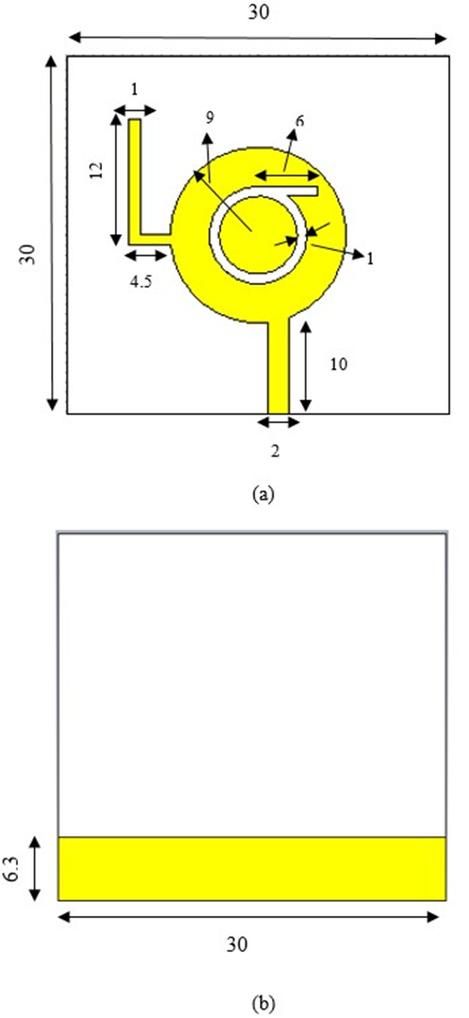
Figure 1. Proposed antenna. (a) Front view and (b) back view (all dimensions in mm).

Figure 2. Various stages of antenna design. (a) stage 1, (b) stage 2, (c) stage 3, (d) stage 4, (e) stage 5, (f) stage 6, and (g) stage 7.
In stage 1, a simple circular patch antenna was designed whose dimensions such as radius were calculated using the following equations [Reference Volakis35, Reference Balanis36]:
 \begin{equation}a = {F \over {\sqrt {1 + {{2h\left( {\ln \left( {{{{{\pi }}F} \over {2h}}} \right)} \right) + 1.7726} \over { \in {{\pi }}F}}} }}\end{equation}
 \begin{equation}F = {{8.791 \times {{10}^9}} \over {\sqrt {{\varepsilon _{\textrm{r}}}} {f_{\textrm{r}}}}}\end{equation}
The optimized radius of the circular patch is chosen to be 9 mm. Integrating various networks on a single device is one of the easy ways to commercialize the WBAN applications. To cater this need, multiband antenna shall be used for integrating multiple communication standards in a single device. Keeping in mind this requirement, in stage 2, a circular ring–shaped slot was introduced in the patch in order to make the antenna to cover more than one band. Aiming the antenna to resonate at 2.45 GHz, the radius of the ring-shaped slot was calculated by taking the relation suggested in paper [Reference Singh, Singh and Singh37] as a model. The equation for the radius of ring-shaped slot is given by equation 3.
 \begin{equation}{a_{{\textrm{slot}}}} = {{7.15} \over {\sqrt {{\varepsilon _{\textrm{r}}}} {f_{\textrm{r}}}}}\end{equation}
In stage 3, a horizontal slot with thickness of 1 mm was introduced and combined with the circular ring slot which makes the overall slot as a sigma-shaped slot. In stage 4, the position of the feed line was made asymmetric and moved toward the right end of the patch to provide better impedance matching. In stage 5, the dimension of the ground plane was reduced which makes partial ground plane to improve the bandwidth performance, thus making the antenna to be characterized as UWB antenna. The length and width of the partial ground plane are given by equations 4 and 5, respectively, [Reference Kumar and Ray38].
 \begin{equation}{L_{{\textrm{partial}}}} = {C \over {1.45f\sqrt \varepsilon }}\end{equation}
 \begin{equation}{W_{{\textrm{partial}}}} = {C \over {4.49f\sqrt {{2 \over {\varepsilon + 1}}} }}\end{equation}
In stage 5, no modifications were done in the front side of the antenna and it is exactly as in stage 4. In stage 6, one horizontal stub was introduced in the patch. Another vertical was introduced and combined with the horizontal stub which makes the antenna to resonate at around 3.45 GHz so that it shall be suitable for 5 G applications also. The expression for evaluating the values for the length of the stub is solved by the guidelines given in paper [Reference Deshmukh and Ray39]
 \begin{equation}{f_{{\textrm{r}} = }}{C \over {\sqrt {{\varepsilon _{\textrm{r}}}} 4{l_{\textrm{e}}}}}\end{equation}
Where le is the effective length which is given by
 \begin{equation}{l_{\textrm{e}}} = {l_{{\textrm{slot}}}} + {{0.4{l_{{\textrm{slot}}}}} \over {{{\sqrt \varepsilon }_{\textrm{r}}}}}\end{equation}
On substituting the effective length given by equation 7 into equation 6, we have the expression for the length of the stub as
 \begin{equation}{l_{{\textrm{slot}}}} = {C \over {{f_{\textrm{r}}}\left( {4{{\sqrt \varepsilon }_{\textrm{r}}}} \right) + 1.6}}\end{equation}
where f r and ε r are the resonant frequency and dielectric constant of the substrate, respectively.
The final proposed design with the dimensions is shown in Fig. 1, which is stage 7 in the antenna design evolution.
The S11 performance and changes during the evolution of various stages is represented in Fig. 3.

Figure 3. Return loss characteristics of various stages of antenna design.
It can be seen through the evolution of various stages that the bandwidth of the antenna keeps on improving. In stage 1, the simple circular patch antenna resonates at 4.2 GHz with harmonics in the higher order modes. In stage 2, a slight shift in the lower order resonance was identified where the higher order harmonics were suppressed. In stage 3, due to the inclusion of a horizontal slot, another resonance was created around 3.5 and 3.7 GHz. In stage 4, as mentioned earlier, placing the feed asymmetrically improves the impedance matching, thereby resulting in decreased return loss values. In all these cases, the bandwidth of the antenna was poor which makes it less suitable for UWB applications. So to increase the operating bandwidth of the antenna, the dimensions of the ground plane was reduced and hence the two resonances in stage 4 shifted to higher frequencies with excellent improvement in bandwidth, which is the stage 5. In stage 6, a small horizontal stub was introduced along with the patch. This shifts the resonance to a higher order values. To further move the resonance, another slot vertical stub was introduced perpendicularly and combined with horizontal stub. This results in resonance at 2.45 GHz ISM band, and 5.8 GHz ISM band with the resonance at 3.45 GHz remaining same. A slight improvement in bandwidth is also found. This is the proposed antenna design. As expected, improvement was observed in both impedance matching and bandwidth.
In order to further compare the performance of the design with other flexible substrate, rubber was chosen and simulation was performed. Following this, the most widely used cost-effective FR-4 substrate was also used. The performance comparison of the proposed structure was done for three substrate materials and presented in Fig. 4.

Figure 4. Return loss characteristics of the antenna on various substrates.
The obtained results show that usage of Rogers 4003C with dielectric constant 3.5 provided good performance satisfying various result parameters such as return loss, bandwidth, gain, and efficiency, and hence it is being considered for discussion in the following sections.
Results and discussion
Analysis of various result parameters plays a crucial role in the design of antennas. Results such as reflection coefficient, voltage standing wave ratio (VSWR), bandwidth, gain, radiation pattern, SAR, etc. are analyzed, and comments are provided.
Reflection coefficient characteristics
The reflection coefficient characteristics is represented in dB as return loss (S11). The simulated and measured return losses of the proposed antenna are shown in Fig. 5.

Figure 5. Return loss characteristics of the proposed antenna.
From the figure, it is seen that the simulated and measured results are in good agreement. In simulated result, the first lower order resonance occurs at 2.45 GHz which is used for ISM band applications. The middle order resonance was created at 3.45 GHz 5 G applications. The higher order resonances occur at 5.8 GHz (ISM) and 9.5 GHz, which operates in the UWB range of frequencies.
An antenna can be called as UWB antenna only if the bandwidth of the antenna is 500 MHz in the UWB range [Reference Mahmood, Ishak, Ismail, Zakaria and Alani34, 40]. To check this, the bandwidth of the proposed antenna was derived from the return loss graph with the reference point as −10 dB. As mentioned earlier, the ground plane dimension played a major role in enhancing the bandwidth of the proposed design. Hence, a parametric analysis was done for the width of the ground plane with various dimensions. This is shown in Fig. 6.

Figure 6. Return loss of the proposed antenna at various ground plane dimensions.
Although the dimension was calculated using mathematical relations, this parametric analysis shall be helpful in finalizing the values. The value taken from the expressions (4) and (5) is 6.3 mm.
A value slightly lower than 6.3 which is 6 mm and slightly higher than 6.3 which is 6.6 mm were taken for analysis. From the analysis, it was found that the value obtained from the mathematical expressions was the most fitting one for high bandwidth.
On observing the return loss characteristics of the proposed antenna, it is found that the antenna covers the entire UWB band from 2 to 10 GHz, thereby providing 106% of bandwidth.
VSWR
The measured VSWR of the proposed antenna is shown in Fig. 7.

Figure 7. VSWR of the proposed antenna.
In general, a good VSWR is a value less than 2, which represents only 10% of standing waves. On observing the graph, it is found that the simulated VSWR is less than 2 from 1.7 to 9.9 GHz. This confirms the proper operation of the antenna in the UWB band.
Efficiency
The overall radiation performance of the antenna is predicted by the parameter efficiency of the antenna, which can be viewed at every particular frequency of interest. The efficiency of the proposed antenna design is depicted in Fig. 8.

Figure 8. Efficiency of the proposed antenna.
The efficiencies of the antenna are represented in dB obtained from CST microwave studio. Converting those values into percentage using basic mathematical calculations, it is found that efficiency of the proposed design is 91%, 95%, 96%, 96% at 2.4, 3.45, 5.8, and 9.5 GHz, respectively.
Radiation pattern
The directionality of the antenna’s radiation is given by the parameter radiation pattern. Figure 9a and b shows the radiation pattern (e-plane and h-plane) of the antenna at 2.4 and 5.8 GHz on free space. It can be inferred that the antenna radiates directionally at 2.45 GHz which makes it suitable for off-body communication [Reference Zhou, Fang and Jia10, Reference Mahmood, Ishak, Ismail, Zakaria and Alani34, Reference Farahat and Hussein41]. At 5.8 GHz, it radiates omnidirectionally which makes it suitable for on-body communication [Reference Tak, Lee and Choi4, Reference Mahmood, Ishak, Ismail, Zakaria and Alani34, Reference Farahat and Hussein41, Reference Singh, Dhupkariya and Bangari42]. Thus, the proposed design can act as a dual-mode antenna for WBAN applications.
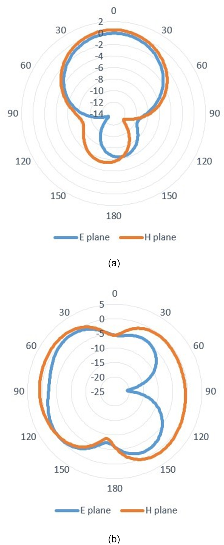
Figure 9. Radiation pattern of the proposed antenna. (a) 2.45 GHz and (b) 5.8 GHz.
Gain
The simulated gain of the proposed antenna is shown in Fig. 10. The simulated gain at 2.45, 3.45, 5.8. and 9.5 GHz is 1.95, 3.23, 3.46, and 5.95 dB, respectively. As WBAN devices will be communicating with other devices or networks which are probably closer to them, the obtained gain values of the proposed design are highly appreciable.

Figure 10. Gain of the proposed antenna.
Within the desired frequency range, the peak gain of the antenna occurs at 7.5 GHz with 6.61 dB.
The comparison of return loss characteristics, gain, and bandwidth of the proposed design for three substrates is shown in Table 1.
Table 1. Comparison

From the table, it is seen that the proposed antenna is smaller in dimensions than the antennas in papers [Reference Yeboah-Akowuah, Kosmas and Chen3, Reference Gupta and Kumar5–Reference Shakib, Moghavvemi and Binti Wan Mahadi7, Reference Zhao, Chao, Hong, Wang and Zheng9, Reference Zhou, Fang and Jia10, Reference Zhao and Geyi18, Reference Singh, Bangari, Ali, Vyas, Verma and Saxena29] and lesser in thickness than in papers [Reference Yeboah-Akowuah, Kosmas and Chen3, Reference Gupta and Kumar5–Reference Shakib, Moghavvemi and Binti Wan Mahadi7, Reference Zhao, Chao, Hong, Wang and Zheng9, Reference Zhou, Fang and Jia10, Reference Zhao and Geyi18, Reference Govindan, Palaniswamy, Kanagasabai, Kumar, Rao and Alsath26, Reference Singh, Bangari, Ali, Vyas, Verma and Saxena29, Reference Kumar, Kumar, Gupta, Sengar, Sharma, Gupta, Kumar, Gupta, Albreem, Ha and Sharma30, Reference Yadav, Singh, Verma and Singh32, Reference Chen, Wang, Liu, Wang and Lin33]. This lesser thickness of the proposed work makes the overall volume lesser. Also, the antenna provides better bandwidth than the antennas reported in papers [Reference Shakib, Moghavvemi and Binti Wan Mahadi7, Reference Veeraselvam, Mohammed, Savarimuthu, Marimuthu and Balasubramanian8, Reference Singh, Bangari, Ali, Vyas, Verma and Saxena29, Reference Kumar, Kumar, Gupta, Sengar, Sharma, Gupta, Kumar, Gupta, Albreem, Ha and Sharma30, Reference Yadav, Singh, Verma and Singh32, Reference Chen, Wang, Liu, Wang and Lin33] and dual-mode operation with good bandwidth than in papers [Reference Gupta and Kumar5, Reference Zhou, Fang and Jia10, Reference Zhao and Geyi18, Reference Saeidi and Karamzadeh31]. The proposed antenna also provides better gain than the antennas reported in papers [Reference Yeboah-Akowuah, Kosmas and Chen3, Reference Kerketta and Ghosh6, Reference Shakib, Moghavvemi and Binti Wan Mahadi7, Reference Zhou, Fang and Jia10, Reference Lai, Wang, Sun, Zhao and Zeng19, Reference Govindan, Palaniswamy, Kanagasabai, Kumar, Rao and Alsath26, Reference Singh, Bangari, Ali, Vyas, Verma and Saxena29, Reference Kumar, Kumar, Gupta, Sengar, Sharma, Gupta, Kumar, Gupta, Albreem, Ha and Sharma30, Reference Yadav, Singh, Verma and Singh32, Reference Chen, Wang, Liu, Wang and Lin33].
On observing the results, it is found that the FR-4 and rubber substrates provide better return loss values. On observing the bandwidth, ROGERS 4003C provides higher bandwidth with good gain, and hence it is chosen for further on-body analysis.
On-body performance
The on-body performance analysis plays a vital role in antennas being used for WBAN. In this context, certain analysis has been done and the results are presented. Here an on-body tissue model with different layers and also a real human subject was used for analyzing the results.
S11 performance analysis
The S11 performance analysis of the antenna in free space and on body and also with a human subject is done, and the results are presented below. An on-body tissue model initially with three layers, namely skin, fat, and muscle, was used for simulation. This means that the antenna is directly placed on the body without any air gap. Then, various air gaps such as 3 and 6 mm were used between the antenna and human multilayer model and the results were analyzed. Figure 11 shows the simulation setup of the antenna on body.

Figure 11. On-body antenna simulation setup. (a) Front view and (b) side view.
The dimension of the body phantom model was chosen to be 100 × 100 mm2, which is a bit larger than the dimensions suggested in papers [Reference Gupta and Kumar5, Reference Shakib, Moghavvemi and Binti Wan Mahadi7]. The thickness and electrical properties of the phantom model were considered as done in paper [Reference Shakib, Moghavvemi and Binti Wan Mahadi7] and presented in Table 3.
Table 3. Electrical properties of on-body tissue model

From the graph (Fig. 12), it is found that when the antenna is directly placed on the human body with no air gap, there is detuning of the lower resonance at 3.45 GHz and the resonance at 2.45 and 5.8 GHz undergo change in loss values. The resonance at 9.5 GHz also slightly shifts to a lower frequency. The shift in resonance occurs toward lower frequency side.

Figure 12. On-body S11 performance analysis.
Later, air gaps were introduced between the antenna and the body phantom considering the fact that a cloth separation (dress) shall be there between the body and the antenna sensor.
When the gap is 3 mm, the antenna exhibits a slight shift in its resonances at 2.45 and 3.45 GHz to a lower value, but the resonance at 5.8 and 9.5 GHz remain almost the same without much effect. Later, a gap of 6 mm was introduced and it was observed that the behavior of the antenna almost remains the same at all the frequencies as compared to free space. Hence, to extract the same performance as it provides in free space, an air gap of 6 mm was used for on-body simulation and analysis.
SAR analysis
For any antenna used for WBAN applications, it is mandatory to analyze SAR. SAR gives information about what quantity of radiated power is entering the body when the antenna in brought to proximity of human body. According to the IEEE C95.3, the value of SAR should be less than 2 W/kg for 10 g of tissue and less than 1.6 W/kg for 1 g of tissue [43].
SAR can be calculated using the following expression:
 \begin{equation}{\textrm{SAR}} = {{\sigma {{\left| E \right|}^2}} \over {2\rho }}\end{equation}
where  $E$—electric field intensity in V/m, $\sigma $—conductivity of the tissue in S/m, and $\rho $—mass density of the tissue in kg/m3.
The SAR analysis has been done for two categories of power such as a high value and a low value of power. Initially, the designed antenna was simulated for SAR analysis with an input power of 1 W for 10 g of tissue. For this power, the SAR was found to be almost closer to the health hazard standard given in papers [Reference Movassaghi, Abolhasan, Lipman, Smith and Jamalipour2, 43]. Hence, the input power was then reduced and set to 0.8 W for SAR analysis [Reference Sakurai, Kiyokawa, Narita, Suzuki, Taki and Miyakoshi44]. For 0.8 W, the SAR value was found to be 0.46 W/kg at 7.5 GHz and 0.57 W/kg at 5.5 GHz, which satisfies the health norms of electromagnetic exposure.
The SAR simulation is shown in Figs. 13 and 14. The percentage reduction in SAR is 77% at 7.5 GHz and 71.5% at 5.5 GHz. Then, to reduce the SAR values of the proposed design even at some higher values of input power, the antenna is backed with a reflector made of ROGERS 4003C as per the suggestions in papers [Reference Veeraselvam, Mohammed, Savarimuthu, Marimuthu and Balasubramanian8, Reference Targonski, Pozar and Waterhouse45, Reference Rowe and Waterhouse46], which is shown in Fig. 15.
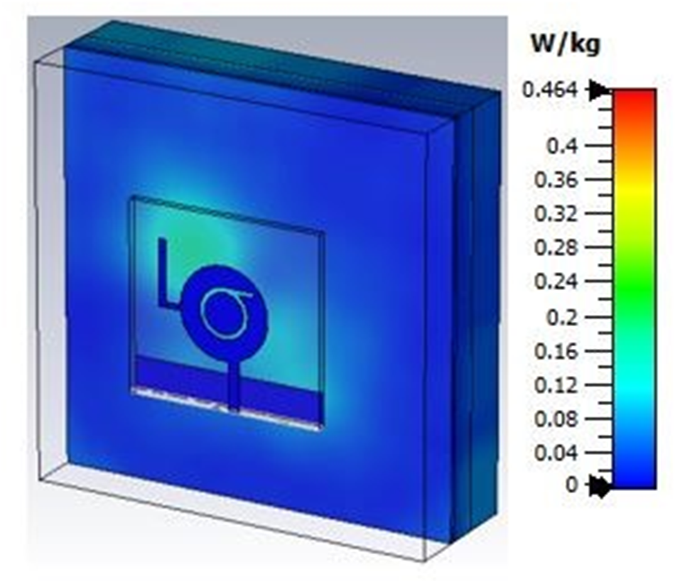
Figure 13. SAR performance without reflector (7.5 GHz).

Figure 14. SAR performance without reflector (5.5 GHz).

Figure 15. Antenna structure with reflector.
The dimension of the reflector is chosen to be 50 × 50 mm2. A spacing of 10 mm is chosen between the antenna and the reflector. This 10 mm value was chosen based on the parametric results obtained from CST microwave studio, below which the bandwidth performance of the antenna slightly deviates. However, the other performance of the proposed antenna shall not get degraded due to the placement of the reflector directly behind the antenna. To ensure this first, the S11, bandwidth and gain performance of the proposed antenna with and without reflector has been studied after which the design has been made. Figure 16 shows the S11 performance.

Figure 16. S11 performance with and without reflector.
From Fig. 16, it can be seen that there is no much variation of S11 and bandwidth values of the proposed design in the presence and absence of reflector.
In order to further validate the performance maintenance of the antenna with reflector, SAR simulation and analysis for the antenna backed with a reflector was done for two kinds of body phantom models. One is with Cartesian model whose sample picture is shown in Fig. 17. Other is cylindrical human arm model whose sample picture is shown in Fig. 18.

Figure 17. SAR at 5.5 GHz Cartesian model.

Figure 18. SAR at 5.5 GHz human arm model.
The SAR results for the antenna with reflector thus obtained are compared with tabulation in Table 4.
Table 4. SAR values

From Table 4, it is evident that the proposed antenna exhibits limited SAR values at 5.5 and 7.5 GHz according to the IEEE health specifications and hence it shall be well suited for WBAN applications [Reference Yeboah-Akowuah, Kosmas and Chen3, 43]. The achieved reduction of SAR in percentage are 75.5% for Cartesian model at 5.5 GHz, 79.95% for cylindrical human arm model at 5.5 GHz, 79% for Cartesian model at 7.5 GHz, and 80.1% for cylindrical human arm model.
Thus, it can be said that, for slightly less values of input power whose values are nearly same as the power values used in papers [Reference Yeboah-Akowuah, Kosmas and Chen3–Reference Zheng, Zhang, Chen and Yan15], the proposed design without reflector which is shown in Fig. 11 can be used as such without making any further modifications. If the power is increased, a suitable reflector can be backed as shown in Fig. 15 to keep the SAR values within the specified levels.
Table 5 shows the comparison of efficiency, bandwidth, and gain of the proposed antenna with and without reflector.
Table 5. Performance comparison (with and without reflector)

From Table 5, the efficiency of the antenna with reflector remains almost same as that of the antenna without reflector (taken at 7.5 GHz). With some improvement in peak gain (at 7.5 GHz), the bandwidth of the antenna with reflector undergoes a change of only 2% which is negligible. This ensures that placing the reflector behind the antenna does not affect the performance of the antenna.
On comparing the technique of placing reflector behind the antenna in papers [Reference Veeraselvam, Mohammed, Savarimuthu, Marimuthu and Balasubramanian8, Reference Targonski, Pozar and Waterhouse45, Reference Rowe and Waterhouse46], the distance of the reflector from the antenna and the dimensions of the reflector used are both quite lesser which ensures the betterment of the proposed design as compared to papers [Reference Veeraselvam, Mohammed, Savarimuthu, Marimuthu and Balasubramanian8, Reference Targonski, Pozar and Waterhouse45, Reference Rowe and Waterhouse46].
Radiation pattern (on body)
The radiation performance of the antenna under on-body condition was studied. Figure 19 shows the measured radiation pattern on free space and simulated radiation pattern under on-body condition at 2.4 and 5.8 GHz. Figure 19 shows that on comparing, the on-body radiation performance exhibits slight glitches with minimum variations. This is due to the additional permittivity effect of human body. However, the device preserves the shape of the pattern without any change under on-body conditions.
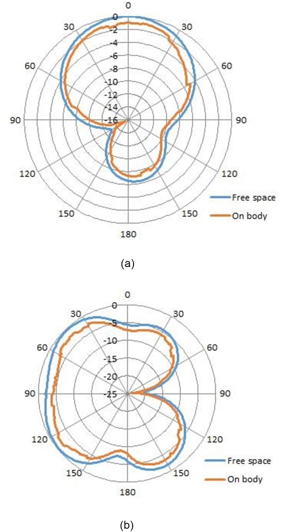
Figure 19. Radiation pattern of the proposed antenna (on body) at (a) 2.45 GHz and (b) 5.8 GHz.
Bending analysis
For WBAN applications, as the devices shall be placed exactly on the body or very close to the body, possibilities exist for the device to be bent due to the shape of the human body.
Flexible and bending nature of antennas offers a favorable solution for body-centric communications [Reference Kirtania, Elger, Hasan, Wiśniewska, Sekhar, Karacolak and Sekhar47, Reference Kumar, Ali and Sharma48]. Hence, the analysis of the antenna performance has been extended to place the antenna on a bending surface and thus the results are evaluated. Figures 20 and 21 show the antenna setup with bending.

Figure 20. Antenna bent in y orientation.

Figure 21. Antenna bent in x orientation.
While bending the antenna, it can be taken up to some fixed radius. In this work, the bending radius of the antenna is taken to be 50, 75. and 100 mm which nearly resembles the bending radius of children and adults [Reference Veeraselvam, Mohammed, Savarimuthu, Marimuthu and Balasubramanian8].
Also, the antenna can be bent in both x orientation and y orientation. Keeping this scenario in mind, the S11 performance of the proposed antenna was studied under aforementioned radii in both x orientation and y orientation whose results are presented in Figs. 22 and 23.
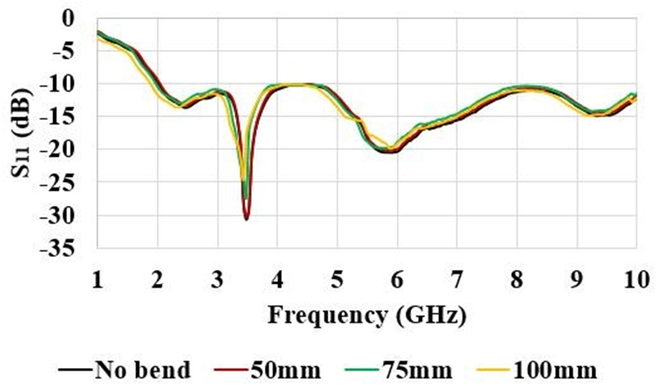
Figure 22. S11 performance under bending conditions (y orientation).

Figure 23. S11 performance under bending conditions (x orientation).
On taking a look into the S11 performance of the proposed antenna under different radii (Figs. 22 and 23), it is observed that the antenna undergoes only slight detuning due to bending effects which ensures the flexible nature of the device proposed.
On bending the antenna in y orientation, changes in S11 of the antenna are observed for the bending radii 75 and 100 mm. For 50 mm radius, the S11 performance is same as that of the no-bending scenario. For 75 mm, the S11 values changed from −30 to −27 dB at 3.45 GHz and remains the same without any noticeable change at other frequencies. For 100 mm radius, the S11 value has changed from −30 to −25 dB at 3.45 GHz and from −21 to −19 dB at 5.8 GHz.
However, the antenna still clearly maintains the S11 requirement (S11 < −10 dB) without any degradation. This minor change in S11 values happen because when the antenna is bent in y orientation, the width of the antenna is disturbed which in turn affects the impedance matching. This results in change in S11 values.
On bending the antenna in x orientation, a slight shift in resonant frequencies of the antenna is witnessed. For the bending radius of 50 mm, the S11 values and resonant frequencies remain the same as in unbent scenario. For 75 mm radius, a slight shift in resonant frequency happens from 3.45 to 3.5 GHz while other resonant frequencies remain the same. For 100 mm radius, a shift in resonant frequencies from 3.45 to 3.53 GHz and from 5.8 to 5.81 GHz is witnessed. This slight shift in resonant frequency does not affect the antenna’s functionality as it is within the prescribed ranges as realized in papers [Reference Mahmood, Ishak, Ismail, Zakaria and Alani34, Reference Kirtania, Elger, Hasan, Wiśniewska, Sekhar, Karacolak and Sekhar47].
Despite some shift in resonant frequencies, the antenna still provides good bandwidth. A slight change in bandwidth from 8 to 7.85 GHz is observed for the bending radius of 100 mm alone. This change in bandwidth is less than 2%, and the proposed antenna still provides the required bandwidth for UWB communication. This shows that the proposed antenna is quite less vulnerable to bending effects.
Analysis at various body locations
Also, the device was checked for its performance at various locations of the body. The locations chosen were an adult human arm, thighs, chest, and on ear phones. The sample images taken during measurements are shown in Fig. 24.

Figure 24. Real-time on-body measurement setup.
To increase the usability of the antenna, the device was also checked under wet condition tied with a water bottle. The bottle was completely filled with water to ensure good humidity. Water droplets were poured at the exterior side also. Figure 24 shows the measurement setup of the antenna at headphone, arms, thighs, chest, and wet conditions respectively in the image.
The S11 performance of the antenna under all the above mentioned conditions is presented in Fig. 25.

Figure 25. S11 performance under various on-body locations.
Transient analysis
To ensure proper transmission of UWB pulse, the transient performance of the antenna has to be studied. This is done in terms of group delay represented as  ${T_{\textrm{g}}}$. It is calculated using the following expression:
 \begin{equation}{T_{\textrm{g}}} = {{{\mathop{\textrm d}\nolimits} \varphi } \over {{\mathop{\textrm d}\nolimits} \omega }}\end{equation}
where  $\varphi $ is the phase component of the signal and $\omega $ is the angular frequency. The group delay of the antenna is shown in Fig. 26.

Figure 26. Group delay.
It is seen that the delay function is less than 1ns for the UWB range which ensures less distortion and proper transmission of the UWB pulse.
Some variation in the group delay function is found from 1.6 to 1.9 GHz. However, it is not in the operating frequency range of the proposed device and hence it shall not be taken into account.
The group delay analyses for the conditions of on-body communication and off-body communication are also done. The orientation of the antenna in the simulation environment is shown in Fig. 27.

Figure 27. On- and off-body group delay setup. (a) Group delay (on body) and (b) group delay (off body).
Two antennas were first created in face-to-face configuration. For on-body group delay, both the antennas were backed up with the three-layer on-body tissue model, as done earlier. For off-body group delay, as it is a communication between an on-body antenna and an external device separated from the body, one antenna was backed up with the three-layer on-body tissue model and another antenna is a standalone antenna. These setups are shown in Fig. 27a and b. The distance between the antennas was chosen to be 20 mm. Both the setups were simulated and the group delay is presented in Fig. 28.

Figure 28. On- and off-body group delay.
It was observed that, the device exhibits constant group delay in free space condition. However, some variations can be observed in the high-frequency range above 8 GHz under both on- and off-body conditions, with slight variation under off-body condition and comparatively a little bit more variation under on-body condition. This is due to the effect of placing on-body tissue model behind the antenna. But the variation is less than 0.5 ns and hence shall be considered.
In the view of comparing the performance of the proposed antenna with existing works, a comparison table is drafted and presented (Table 2). It is inferred from the table that the sigma slotted antenna has not done anywhere before to the best of authors knowledge. The proposed antenna works well in dual mode for WBAN applications with good bandwidth, gain and reduced size compared to existing works. The group delay of the antenna is also flat.
Table 2. Performance comparison with related works

Conclusion
A wearable dual-mode UWB antenna with sigma-shaped slot has been designed and presented in this paper. The antenna is suitable for wireless body-centric communications supporting both on-body and off-body modes of communication. The proposed design is much more simple in construction without any sacrifice in performance, thereby providing minimum return loss and VSWR, good bandwidth (106% of UWB band), gain, high efficiency, and less distorted radiation pattern. All the simulated results were found to be in good agreement with the measured results. The SAR analysis and bending analysis were also performed which provided excellent results which abide by the regulations provided by IEEE. Also, the tests performed under wet conditions, antenna at human chest, arms, thighs, and head phones provide good results. The group delay of the antenna is also constant which ensures stable characteristics with less distortion in the UWB range. Thus, the proposed antenna design can be highly suitable for WBAN applications.
Acknowledgments
None.
Competing interests
The authors declare hereby that there are no competing interests in publishing the paper in any form.

P. Venkatesh obtained his bachelor’s degree and master’s degree from Anna University, Chennai. He now serves as Assistant Professor in the Electronics and Communication Engineering department of Ramco Institute of Technology. He has 8 years of teaching experience. His area of interests includes antenna design and analysis for wireless applications, VLSI design technology and artificial intelligence & machine learning. He has published more than six research papers in international journals. He is a life member of ISTE.

T. V. Narmadha obtained her AMIE (EEE) from the Institution of Engineers, India, and M.E. and PhD degrees from College of Engineering, Anna University, Chennai, India. Currently, she is a professor in the Department of Electrical and Electronics Engineering, St. Joseph’s College of Engineering, Chennai, India. She has more than 21 years of teaching experience. She has published more than 30 research papers in national and international journals/conference proceedings. Her teaching and research interests include electrical drives, medical image processing, auto-tuning, control using fuzzy logic, neural networks, and genetic algorithm. She is an associate member of IE (I).


