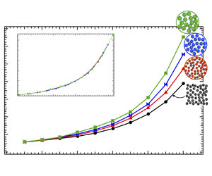
1. Introduction
In both living and non-living suspensions, confinement of macromolecules within a cavity limits the space that colloidal particles can explore, which is useful for delivery or sequestering of macromolecules in therapeutics, chemical interactions or coatings. Examples include membraneless organelles in biological cells, liposome-based microreactor vesicles and particle-filled droplets that promote uniform deposition of ink colour or 3D-printed polymeric materials. Recent work has shown that the interplay between confinement and particle concentration impacts the equilibrium dynamics of suspended colloidal particles. The origins of these effects are both entropic and hydrodynamic. Entropically, confinement of a colloidal suspension restricts the spatial arrangements within the cavity that particles can explore. However, low-entropy particle layering near the wall counters this restriction by allowing more configurations in the bulk, thus maximising the configurational states (Gonzalez, Aponte-Rivera & Zia Reference Gonzalez, Aponte-Rivera and Zia2021). This spatially heterogeneous ordering, in turn, affects hydrodynamic interactions. Combined, entropic restriction and particle–cavity hydrodynamic interactions were recently shown to qualitatively change particle diffusion, making short-time self-diffusion anisotropic and position-dependent. Size polydispersity produces additional entropic effects such as demixing (Gonzalez et al. Reference Gonzalez, Aponte-Rivera and Zia2021; Savranskaia, Egli & Valet Reference Savranskaia, Egli and Valet2022). The fundamental connection of diffusion to viscosity was recently used to show that confinement alters equilibrium rheology of confined colloidal suspensions (Aponte-Rivera & Zia Reference Aponte-Rivera and Zia2021). However, away from equilibrium, various conditions can produce recirculating and other flows in confined colloidal suspensions (Brangwynne et al. Reference Brangwynne, Koenderink, MacKintosh and Weitz2009; Shinar et al. Reference Shinar, Mana, Piano and Shelley2011; Saintillan, Shelley & Zidovska Reference Saintillan, Shelley and Zidovska2018) that are central to the growth and division of biological cells, the spreading of industrial particle-laden droplets and the motion of drug-delivery vesicles. Such flows of confined, hydrodynamically interacting Brownian particles have been observed experimentally in release of pendant droplets and capillary breakup (Li et al. Reference Li, Ji, Sun, Lan and Wang2019).
Computational modelling provides an important complement to experimental measurement of particle dynamics and rheology in suspensions. A mature foundation exists for the modelling of unconfined suspension rheology that recovers many seminal results found in experimental measurements, thus validating the methods used to model the microscopic physics in dynamic simulations. The combined approach of experiment, theory and simulation has produced a deep understanding of the suspension mechanics that affect rheology, where modelling gives particular insight into particle dynamics and the relative roles of microscopic forces. However, far less is known about how confinement affects non-equilibrium rheology.
Computational modelling is a key complement in the search for understanding of how non-equilibrium viscosity, osmotic pressure and diffusion affect processes in non-living (Farokhirad, Lee & Morris Reference Farokhirad, Lee and Morris2013; Palmer et al. Reference Palmer, Chun, Morris, Mundy and Schenter2020) and living confined systems (Shinar et al. Reference Shinar, Mana, Piano and Shelley2011), where visualisation and tracking of exact particle locations is possible over periods of time inaccessible in experiments, and permits direct measurement rheological properties. For example, Saintillan and coworkers showed via modelling of polymer physics and hydrodynamics that active motion generated by chromatin produces cooperative dynamics that regulate gene expression (Saintillan et al. Reference Saintillan, Shelley and Zidovska2018). Spakowitz and coworkers integrated polymeric forces and confinement into their models to demonstrate how epigenetic modifications are implicated in chromatin segregation, actually replicating experimental observations (MacPherson, Beltran & Spakowitz Reference MacPherson, Beltran and Spakowitz2018). As a final example, Shelley and coworkers demonstrated that cell spanning recirculating flows enabled the pronuclear complex proper positioning and orientation (Shinar et al. Reference Shinar, Mana, Piano and Shelley2011). These huge strides show that computational modelling can unveil the colloidal biophysics that underlies cellular behaviour. Although previous work has done remarkable progress to consolidate computational modelling as a tool to interrogate phenomena at the mesoscale, up to know there was not a computational model capable to capture the combined effects of Brownian motion, confinement, hydrodynamics and crowding. To such end, Zia and coworkers developed the confined Stokesian dynamics (CSD) algorithm to study the microhydrodynamics of spherically confined suspensions of hard Brownian spheres (Aponte-Rivera & Zia Reference Aponte-Rivera and Zia2016; Aponte-Rivera, Su & Zia Reference Aponte-Rivera, Su and Zia2018; Aponte-Rivera & Zia Reference Aponte-Rivera and Zia2021; Gonzalez et al. Reference Gonzalez, Aponte-Rivera and Zia2021). In CSD, the coupling of cavity and particle surfaces via hydrodynamic mobility tensors produces particle motion that recovers experimentally observed entrainment of particles in recirculating flows in biological cells (Brangwynne et al. Reference Brangwynne, Koenderink, MacKintosh and Weitz2009; Aponte-Rivera & Zia Reference Aponte-Rivera and Zia2021) as well as anisotropic and spatially heterogeneous diffusion (Aponte-Rivera & Zia Reference Aponte-Rivera and Zia2016; Gonzalez et al. Reference Gonzalez, Aponte-Rivera and Zia2021). This algorithmic approach can tease apart the separate contributions from hydrodynamic and entropic forces to help explain biomolecular localisation and membraneless compartmentalisation in cells. Rheology of the cytoplasm is also of interest; although confined two-point rheology can obtain viscosity from particle displacements (diffusion) in such systems, the theory is limited to equilibrium and cannot predict osmotic pressure or flow rheology. Although the original Stokesian dynamics framework (Durlofsky, Brady & Bossis Reference Durlofsky, Brady and Bossis1987; Bossis & Brady Reference Bossis and Brady1989; Sierou & Brady Reference Sierou and Brady2001; Banchio & Brady Reference Banchio and Brady2003) excels at modelling flowing colloidal suspensions, the original CSD framework was restricted to equilibrium conditions because the underlying theoretical framework did not yet include elements of the hydrodynamic couplings between particle motion and stress essential to modelling flow. We tackle that challenge in the present work.
Flow induces non-equilibrium stress in pure fluids and in suspensions. The stress is a tensor, where off-diagonal elements pertain to deviatoric stress and diagonal elements pertain to osmotic pressure. These quantities take on non-Newtonian character in colloidal suspensions that are of interest as discussed previously. It is the objective of this study to expand the CSD framework to model this behaviour. We utilise the basic approach of Stokesian dynamics, leveraging the linearity of Stokes flow that connects particle motion to suspension rheology, in particular a tensor known as the stresslet that relates suspension stress and, in turn, to osmotic pressure and viscosity to suspension dynamics.
In this Part 1 of a two-part series, we report the hydrodynamic functions that define the traceless stress tensor of confined colloidal suspensions of hydrodynamically interacting spheres, including many-body hydrodynamics and lubrication interactions. The first step in this effort is the development of the resistance and mobility functions that couple particle motion to the hydrodynamic stresslet. We then develop averaging techniques and algorithmic implementation into CSD. After we present the theoretical framework for the traceless elements of the stresslet, we follow this with an application of these relations: we implement them into the model and measure viscosity of a spherically confined suspension. We do so by formulating an expression for the high-frequency viscosity of a confined colloidal suspension using energy methods to relate the stresslet to particle motion and flow, reflecting the fact that the viscosity of a suspension reflects the way particle motion, particle interactions and the bulk motion of suspending fluid dissipate energy. Measured via traditional bulk shear macrorheology, the viscosity is defined as the proportionality constant between the suspension stress and the strain rate in the suspension. Energy methods provide a powerful means to unify these two descriptions, by relating the rate of mechanical energy dissipation to the suspension stress and the velocity of the suspended particles. Similar approaches (Happel & Brenner Reference Happel and Brenner1981) for unconfined suspensions have been shown to accurately reproduce experimental measurements (Su, Swan & Zia Reference Su, Swan and Zia2017), providing support for the energy-methods approach. However, prior approaches, in both unconfined and confined suspensions, lacked the theoretical expressions that produce higher-order hydrodynamic traction moments on particle surfaces essential to predicting the confined suspension stress. To model concentrated suspensions, we developed the theoretical expressions using microhydrodynamics methods that account for many-body hydrodynamic interactions which, when inserted into our energy methods model, predicts the high-frequency viscosity from the suspension stress for confined suspensions from dilute to concentrated suspensions at different levels of crowding and polydispersity.
We compare our results to those obtained recently via a confined generalised Stokes–Einstein relation for two-point microrheology (Aponte-Rivera & Zia Reference Aponte-Rivera and Zia2021) that predicts the linear-response moduli of a confined suspension of hydrodynamically interacting colloids using the correlated motion of two embedded tracer colloids. Fundamentally, the two approaches, directly calculating the suspension stress and extracting the viscosity from it vs measuring particle correlations and relating them to viscosity via a Stokes–Einstein relation, both rely on the idea of energy dissipation. However, the two approaches differ in the qualitative perturbation used: bulk flow associated with shear vs particle displacements associated with forces. In unconfined suspensions, these two approaches show the same qualitative trends for the equilibrium viscosity over all time scales: dissipation (viscosity) that increases moderately with increased packing at low concentration but increases sharply at high concentration (see the summary in Zia Reference Zia2018). The validity of Stokes–Einstein relations is formally well-defined only for suspensions of freely mobile particles not close the jamming transition. This cross-comparison of microrheology to shear rheology will be examined here for confined suspensions, an essential step in robust modelling of confined suspensions and for building a framework for understanding how confinement optimises behaviour of particle-laden vesicles and understanding how physics regulates the function of biological cells.
The remainder of this article is organised as follows. In § 1 the model systems describing two-body theory and concentrated suspensions are presented. The definitions and nomenclature of the hydrodynamic mobility and resistance formulations utilised throughout this work are given in § 2. Then, the two-body theory required to model the hydrodynamic stress of confined suspensions is derived, first for axisymmetric flows in § 3 and then for transverse flows in § 4. In addition, in § 4 a generalised method to solve the Stokes equations in bispherical coordinates is presented. These new theoretical results are validated in § 5 by recovering prior work for confined suspensions. The formulation for the many-body stress of a confined suspension according to the framework of the CSD is introduced in § 6 alongside the definition of the high-frequency viscosity based on the suspension stress. We conclude this work in Appendices A–L with a discussion about the implications of the recent work to the study of confined suspensions.
2. Theoretical framework
2.1. Model systems
We model the dynamics of a suspension of hard colloidal spheres of varying sizes $a_i$ suspended in a Newtonian solvent of density $\rho$ and viscosity $\eta$, all enclosed in a hard spherical cavity of size $R$. Here, $i$ refers to particles of a given size. The motion of the particles sets the surrounding fluid into motion, where the small size of the colloids produces a vanishingly small Reynolds number $Re=\rho U a/\eta$, where $U$ is the characteristic particle velocity. As a result, fluid motion is governed by the Stokes equations, and because the particles are freely mobile, their motions are coupled to each other and with the enclosing cavity by many-body reflected hydrodynamic and lubrication interactions. Accounting for Brownian motion, hydrodynamic interactions and other deterministic forces in colloidal suspensions can be done analytically for a pair of particles, but requires computational methods beyond the semi-dilute limit. Properly accounting for Stokesian particle dynamics in such systems requires two challenges to addressed: first, representing near-field hydrodynamic interactions near contact, which become divergent lubrication forces; the second challenge is representing infinitely reflected fluid-mediated interactions between many particles simultaneously, i.e. many-body hydrodynamic interactions. One approach for addressing these challenges is the Stokesian dynamics algorithm (Durlofsky et al. Reference Durlofsky, Brady and Bossis1987; Bossis & Brady Reference Bossis and Brady1989; Sierou & Brady Reference Sierou and Brady2001; Banchio & Brady Reference Banchio and Brady2003), developed for unconfined suspensions, which leverages the linearity of Stokes flow to solve the near-field and many-body problems separately and then superimpose them for a complete solution.
CSD expands that framework by incorporating a spherical enclosure, enabling measurement of its effect on particle microstructure and hydrodynamic interactions for monodisperse (Aponte-Rivera & Zia Reference Aponte-Rivera and Zia2016; Aponte-Rivera et al. Reference Aponte-Rivera, Su and Zia2018) and polydisperse (Gonzalez et al. Reference Gonzalez, Aponte-Rivera and Zia2021) suspensions. To do so, we expanded mobility functions derived from Ladyzhenskaya's integral equation (Ladyzhenskaya Reference Ladyzhenskaya1963) which we combined with Faxén relations to represent the enclosure. These functions were superimposed with previously developed near-field theory (Jeffery Reference Jeffery1915; Stimson & Jeffery Reference Stimson and Jeffery1926; Dean & O'Neill Reference Dean and O'Neill1963; O'Neill Reference O'Neill1964; Majumdar Reference Majumdar1967; Cooley & O'neill Reference Cooley and O'neill1968; O'Neill & Majumdar Reference O'Neill and Majumdar1970a; Jeffrey & Onishi Reference Jeffrey and Onishi1984; Jeffrey Reference Jeffrey1992; Jones Reference Jones2009). We used the resulting CSD model to study equilibrium diffusion in concentrated confined monodisperse and polydisperse suspensions (Aponte-Rivera et al. Reference Aponte-Rivera, Su and Zia2018; Gonzalez et al. Reference Gonzalez, Aponte-Rivera and Zia2021). This model was limited to equilibrium conditions however, because some elements of the hydrodynamic functions were not yet developed: the coupling between particle motion and the hydrodynamic stresslet, the symmetric first moment of the hydrodynamic traction on particle surfaces. We compute these new hydrodynamic functions in the present work. We get started by defining coordinate reference frames that facilitate solving the near-field and many-body problems for confined suspensions. Two coordinate systems are needed and are described here because they will be used throughout subsequent sections to solve the Stokes equations and relate these solutions to the rheology of confined suspensions.
For pair interactions (particle–particle or particle–cavity), the reference frame is identical to an unbound pair (centred on a colloidal particle). Placing the origin at the centre of a particle facilitates transformations between Cartesian, spherical, cylindrical and bispherical coordinates needed to construct and solve the relevant equations of motion and boundary conditions which requires going back and forth between coordinate systems. To model just the pair-level hydrodynamic interactions between a colloid and the cavity, the origin of a Cartesian and curvilinear coordinate systems (cylindrical, spherical and bispherical) is located at the centre of the colloid, as shown in figure 1(a). Here, $\boldsymbol{r}$ denotes the centre-to-centre vector between the cavity and the colloid with the origin at the colloid centre. For pair theory, the geometry of the system is fully specified by the particle position and the particle-to-cavity size ratio $\lambda _c=a/R$ and $\boldsymbol{r}$, equivalently called ‘confinement ratio’ throughout this article.
In contrast, many-body interactions require placement of the origin at the centre of the confining cavity (figure 1b), as though it were itself the reference particle, which facilitates the discretisation of the volume inside the cavity throughout which particles interact. The centre-to-centre vector between the cavity and any colloid is opposite in sign to that used for particle–particle interactions. For monodisperse confined suspensions of $N$ particles, the composition of the system is fully specified by the particle-to-cavity size ratio $\lambda _c=a_1/R$ and the volume fraction $\phi = \lambda _c^3 N$. However, for a polydisperse confined suspension with $M$ different particle sizes $a_1< a_2< \cdots < a_M$, one must also specify $M-1$ particle size ratios $\lambda _{p(i)} = a_i/a_1$ and $M-1$ volume compositions $\phi _i/\phi$, where $\phi = \sum _i^M\phi _i$ and $\phi _i = 4/3{\rm \pi} a_i^3n_i$ and $n_i$ the number density of particles with radius $a_i$. To facilitate the analysis of the suspension dynamics, particles are tracked by the position of their particle centres, $\boldsymbol{r}$, and located in one of 100 concentric bins of constant width $\Delta r/R$. The edge of the outermost bin corresponds to the location of the centre of the smallest particle when it is at contact with the cavity wall and each bin is identified by its radial midpoint $r_m$ (between the innermost and outermost edges), see figure 1(b).
2.2. Mobility and resistance formulations
Viscosity, viscoelastic moduli, osmotic pressure and normal-stress differences are all elements of the stress tensor. Thus, obtaining the stress tensor is one of the first steps in characterising the complete rheology of a material. In a colloidal suspension, the stress differs from that of the suspending fluid and of the material properties of the suspended particles, as demonstrated by bulk rheological experiments (Mewis & Wagner Reference Mewis and Wagner2011). Batchelor (Reference Batchelor1970) showed that the average suspension stress can be obtained as an average over the entire volume, solvent plus particles:
The angle brackets signify an average over the entire suspension $\langle {\cdot }\rangle$, the fluid only $\langle {\cdot }\rangle _f$, or the particle phase only $\langle {\cdot }\rangle _{PP}$. The first term on the right-hand side gives the dynamic pressure $p$ averaged throughout the fluid phase; here, $\boldsymbol {I}$ is the identity tensor. In the second term the strain rate $e$ is averaged over the fluid and particles, for all configurational arrangements. The stress contributed by the particle phase, $\langle \boldsymbol{\varSigma }\rangle _{PP}$, is averaged over all particle configurations. Batchelor (Reference Batchelor1970) showed that the configuration average in homogeneously deformed suspensions is equivalent to a volume average. Related to this result, the particle-phase stress emerges from the interface with the fluid, producing a surface integral that depends on the configuration of the particles:
Here $V$ is the total volume of the suspension, $N$ is the total number of particles, $S_{P,i}$ is the surface of particle $i$ and $\boldsymbol{n}$ is a unit normal vector pointing outward from the particle surface. We evaluate the fluid stress $\boldsymbol{\sigma }$ and velocity $\boldsymbol{v}$ at the particle surface. The first term in (2.2) is the first moment of the surface traction $\boldsymbol{t}=\boldsymbol{\sigma }\boldsymbol{\cdot}\boldsymbol{n}$ exerted by the fluid on a particle, which induces stress. The second term accounts for particle deformability that can reduce stress. The first moment of the traction can be separated into its symmetric and antisymmetric parts,
The antisymmetric part is the hydrodynamic torque tensor and exerts no dynamical influence on the suspension stress for a suspension of hard spheres. The symmetric part defines the hydrodynamic stresslet on particle surfaces:
The deformability term is zero for hard particles, but we retain it in the expression for the stresslet because it is useful for imposing an infinitesimal deformation to solve the Stokes equations for a straining flow, an essential step in developing the missing hydrodynamic functions. This mathematical tool of imposing a perturbative flow to obtain hydrodynamic functions has been used previously in similar stresslet calculations for an unbound pair of hard spheres (Jeffrey Reference Jeffrey1992). The foregoing expression shows that calculation of the average suspension stress and suspension rheology thus requires calculation of the hydrodynamic stresslet in its general, configuration-dependent form and must capture the effect of hydrodynamic interactions on the total fluid stress. In Appendix A, we provide a brief recap of the moments of the surface traction that produce hydrodynamic force, torque and stresslet; for an $N$-particle suspension, the method of multipole Taylor expansion of Ladyzhenskaya's integral equation (Ladyzhenskaya Reference Ladyzhenskaya1963) for flow velocity that relates these couplings to fluid flow; and implementation of Faxèn formulae that relate particle motion to these hydrodynamic traction moments through a grand mobility matrix (GMM), $\mathcal {M}$, and, in turn, a grand resistance matrix (GRM), $\mathcal {R}$. These matrices are discussed next.
As outlined in Appendix A, the microhydrodynamics formalism provides a compact expression of the linearity of Stokes flow of a suspension relating the surface traction exerted by the fluid on particle surfaces to particle motion:
Here, ${\boldsymbol {F}}^H$, ${\boldsymbol {L}}^H$ and ${\boldsymbol {S}}^H$ are vectors and tensors containing the hydrodynamic force, torque and stresslet on the surfaces of each of the $N$ particles in the suspension. Each is linear in the boundary conditions, i.e. particle motion relative to the fluid: ${\boldsymbol {U}} - {\boldsymbol {U}}^\infty$, $\boldsymbol{\varOmega } - \boldsymbol{\varOmega }^\infty$, ${\boldsymbol {E}}-{\boldsymbol {E}}^\infty$, translation, rotation and straining motion, respectively. In the present case, there is no imposed flow, thus ${\boldsymbol {U}}^\infty = \boldsymbol{\varOmega }^\infty = \textbf {0}$ and ${\boldsymbol {E}}^\infty = \textbf {0}$. The particles can also move owing to Brownian motion and interparticle forces. Disregarding the origin of particle motion, the GRM couples the traction moments to motion. More specifically, GRM contains tensors that couple force to translation (${\boldsymbol {R}}^{FU}$), rotation (${\boldsymbol {R}}^{F\varOmega }$), straining motion (${\boldsymbol {R}}^{FE}$) and an infinitude of higher-order couplings as indicated by the ellipses (see Appendix A). Each of these block matrices within the GRM contains the geometrical transformation for all $N$ suspended particles that relate a particle motion to a surface traction moment. A similar linearity relation defines how prescribed motion produces hydrodynamic traction moments:
The GRM $\mathcal {R}$ and the GMM $\mathcal {M}$ hold a reciprocal relationship
so generating either provides access to the other.
To extract motion along and transverse to the line of centres $\boldsymbol {\hat {r}}$ connecting interacting particles, each tensor within the GRM can be projected through orthogonal bases, $\boldsymbol {\hat {r}}\boldsymbol {\hat {r}}$ and $\boldsymbol {I} -\boldsymbol {\hat {r}}\boldsymbol {\hat {r}}$ that set the direction of hydrodynamic coupling, each scaled by a configuration-dependent scalar function that sets the decay of the coupling with separation distance. We illustrate this result with the familiar couplings between translation and rotation that induce hydrodynamic translation and rotational drag:
Here, the coefficients $X(\mathcal {C})$ and $Y(\mathcal {C})$ are scalar resistance functions that encode the configuration-dependent coupling of motion along and transverse to the line of centres $\hat {\boldsymbol{r}}=\boldsymbol{r}/r$ between a particle and the cavity. The superscripts $A$, $B$ and $C$ refer to the force/translation, torque/translation and torque/rotation couplings, respectively. The variable $\mathcal {C}$ defines system configuration, including particle size and particle-to-cavity size ratio. For a single confined particle, $\mathcal {C} = \mathcal {C}(r, \lambda _c)$. For concentrated monodisperse suspensions, $\mathcal {C} = \mathcal {C}(r, \lambda _{c},\phi )$ ($\lambda _p$ does not matter). For concentrated polydisperse suspensions of $K$ different particle sizes, $\mathcal {C} = \mathcal {C}(r, \lambda _{c(1)}, \lambda _{p(2)},\ldots,\lambda _{p(K)},\phi, \phi _i/\phi,\ldots, \phi _K/\phi )$, where $\lambda _{c(1)}\equiv a_1/R$ is the smallest particle-to-cavity ratio, $\lambda _{p(i)}\equiv a_i/a_1>1$ is the particle-to-particle size ratio defined with respect to the smallest particle, and $\phi /\phi _i$ is the ${\textit {i}}{\rm th}$ partial volume fraction. Here, the dimensions of the resistance tensors are captured by the prefactors $6{\rm \pi} \eta a^n$ which also render the hydrodynamic functions dimensionless. Finally, $\delta _{ij}$ is the Kronecker delta, and $\epsilon _{ijk}$ is the Levi-Civita or alternating tensor.
The goal of the present work is to obtain the total suspension stress via the hydrodynamic stresslet; we thus focus specifically on those resistance tensors relating the stresslet to particle motion. The relevant resistance tensors from the GRM are
The superscripts, $G$, $H$ and $M$ indicate the stresslet/translation, stresslet/rotation and stresslet/straining coupling.
Each of the hydrodynamic functions (2.8)–(2.13) encodes the influence of the specific flow associated with a given surface traction, each being chosen to reveal particle motion and rheology of interest. The function $X^A$ (2.8) corresponds to the hydrodynamic force on the colloid associated with axisymmetric translation along the line of centres. This line of centres is shown for a particle inside a sphere in figure 2(a) as the z-axis. The function $Y^A$ plays the same role for translation transverse to the line of centres, where the axis is chosen here for convenience to be along the x-axis in figure 2(b). We could equivalently choose motion along the y-axis. The stresslet sought here can arise from uniaxial, shear and planar-elongational flows, and the corresponding couplings of superscript $G$, $H$ and $M$ each have longitudinal and transverse components $X^G$, $X^M$, $Y^G$, $Y^H$, $Y^M$ and $Z^M$. Here, the $Z$ coupling corresponds to transverse-planar straining motion, related to uniaxial, shear and planar-elongational flow depicted in figures 2(a)–2(c).
The expressions (2.8)–(2.10) and (2.11)–(2.13) have been previously derived for unbound dilute suspensions (Jeffrey & Onishi Reference Jeffrey and Onishi1984; Jeffrey Reference Jeffrey1992) and that framework subsequently leveraged to derive corresponding hydrodynamic functions for concentrated, unconfined suspensions (Durlofsky et al. Reference Durlofsky, Brady and Bossis1987; Ladd Reference Ladd1990; Sierou & Brady Reference Sierou and Brady2001). In these unconfined conditions, all entries shown in (2.7) for the GMM and GRM in are available. In contrast, the corresponding pair-level functions for spherical confinement, which are necessary for developing the confined, concentrated framework, are incomplete. Specifically, there is no existing theory for hydrodynamic functions that represent the stresslet for any flow, nor functions to represent straining flows, for a particle inside a spherical cavity. These resistance tensors are essential both for the near-field interactions between pairs and for many-body interactions; these are, in turn, required to calculate rheological properties of crowded suspensions by means of the confined Stokesian algorithm. Earlier models of the dynamics of a confined particle truncate the GRM, using only the forces and torques produced from translational and rotational flows (2.8)–(2.10) (Jeffery Reference Jeffery1915; Stimson & Jeffery Reference Stimson and Jeffery1926; Dean & O'Neill Reference Dean and O'Neill1963; O'Neill Reference O'Neill1964; Majumdar Reference Majumdar1967; Cooley & O'neill Reference Cooley and O'neill1968; O'Neill & Majumdar Reference O'Neill and Majumdar1970a; Jones Reference Jones2009), which is sufficient for modelling equilibrium diffusion of a confined suspension (Aponte-Rivera & Zia Reference Aponte-Rivera and Zia2016; Aponte-Rivera et al. Reference Aponte-Rivera, Su and Zia2018). The strategy used in these earlier studies was to solve the Stokes equations for a translating sphere and a rotating sphere, and then calculate the surface traction moments $\boldsymbol{F}^H$ and $\boldsymbol{L}^H$.
For a particle inside a spherical cavity, solution of Stokes’ equations for the pressure and velocity fields follows solutions of Laplace's equation with boundary conditions on both surfaces (Appendix B). Jeffery (Reference Jeffery1912) developed a solution using bispherical coordinates, elegantly describing a pair of spheres either internal or external to each other (Appendix B). Jeffery's approach underlies all subsequent bispherical-coordinates solutions to Stokes equations for a pair of spheres (internal or external to each other) (Jeffery Reference Jeffery1915; Stimson & Jeffery Reference Stimson and Jeffery1926; Dean & O'Neill Reference Dean and O'Neill1963; O'Neill Reference O'Neill1964; Majumdar Reference Majumdar1967; Cooley & O'neill Reference Cooley and O'neill1968; O'Neill & Majumdar Reference O'Neill and Majumdar1970a; Jones Reference Jones2009). A brief overview of the development of this body of solutions is as follows. Jeffery (Reference Jeffery1915) contributed the methodology of solving Stokes’ equations in bispherical coordinates and with that methodology, he contributed the flow and pressure due to axisymmetric rotation of a pair of spheres and, from it, calculated the hydrodynamic torque. Next, Stimson & Jeffery (Reference Stimson and Jeffery1926) solved the problem of axisymmetric translation and the corresponding hydrodynamic force on the sphere. In that work, they simplified the mathematics substantially by representing the Stokes’ stream function in bispherical coordinates.
The problems of a sphere rotating and translating transverse to an enclosing cavity were solved by O'Neill & Majumdar (Reference O'Neill and Majumdar1970a) using a method developed by Dean & O'Neill (Reference Dean and O'Neill1963) for a sphere near a flat wall, which used a separation of variables method. Examining the problem in cylindrical coordinates revealed that the $\theta$ component of the velocity and pressure fields is independent of the two other coordinates ($\rho,z$) and that those two coordinates can be equivalently described in any coordinate system of revolution (e.g. cylindrical, spherical and bispherical coordinates, among others). Here Dean & O'Neill (Reference Dean and O'Neill1963) proposed an ansatz in cylindrical coordinates $\{\rho,z,\theta \}$ where the angular dependence of the pressure and velocity fields is independent of their spatial dependencies in the radial and axial directions. After utilising this ansatz in the equation of motion, the resultant second order differential equations were solved in bispherical coordinates as a special case of the solution to Laplace's equation reported by Jeffery, which is discussed in detail in § 3.3. This separation of variables approach was applied to the problems of a sphere translating and rotating transverse to the enclosing spherical cavity by O'Neill & Majumdar (Reference O'Neill and Majumdar1970a). The authors reported expressions for the force and torque on the colloid for both velocity fields. The methods based on bispherical coordinates also give solutions to Stokes’ equations and the surface traction moments for two external spheres, which preceded and are equivalent to the work based on twin multipole methods (Jeffrey & Onishi Reference Jeffrey and Onishi1984; Kim & Karrila Reference Kim and Karrila1991; Jeffrey Reference Jeffrey1992; Jeffrey, Morris & Brady Reference Jeffrey, Morris and Brady1993). In summary, this work produced the force and torque entries in the GRM for a particle in a spherical cavity. In the present work, we utilise these methods to derive additional entries in the GRM.
In the next section, we present the methods for obtaining solutions to Stokes’ equations in bispherical coordinates for three mutually orthogonal straining flows (shown in figure 2) for a spherical colloid inside a cavity. In addition, we present the new expressions derived here for calculating the stresslet on the colloid, and the corresponding hydrodynamic functions for translational, rotational and straining flows ((2.11), (2.12) and (2.13)).
3. Stresslet formulation: pair theory in confinement
In this section we present three primary results required to achieve our goal of completing the confined GRM. We first present new solutions to Stokes’ equations for the three straining flows inside a spherical cavity illustrated in figure 2. We developed a generalised method for solving the Stokes equations in bispherical coordinates to obtain these solutions, which is also shown here. We then combine the solutions of Stokes’ equations obtained in this work together with previous solutions for translational and rotational flows to deduce all hydrodynamic functions associated with the stresslet in the GRM (2.11)–(2.13).
Here we describe the process we follow in the coming sections. In §§ 3.1 and 3.3 we determine velocity and pressure in the fluid phase. We do this by solving the Stokes equations that govern the fluid velocity and pressure point-wise throughout the suspension in both the fluid phase and the particle phase:
for each of the flows shown in figure 2. We then use the velocity and pressure to calculate the fluid-phase stress $\boldsymbol{\sigma }= -p\boldsymbol{I} + \eta (\boldsymbol {\nabla }\boldsymbol{v}+ (\boldsymbol {\nabla }\boldsymbol{v})^{\rm T})$, which is, in turn, used to compute the hydrodynamic stresslet exerted by the flow on an individual particle of radius $a$ and surface area $S_a$:
The superscript $TL$ indicates that the hydrodynamic stresslet $\boldsymbol{S}^{H}$ in (2.4) has been made traceless in (3.2). The trace is associated with the osmotic pressure, which we study separately in the second part of this two-part series. After solving the Stokes equations and obtaining the traceless stresslet, we combine it with the linearity expressions (A9), and the definitions of $\boldsymbol {R}^{SU}$, $\boldsymbol {R}^{S\varOmega }$ and $\boldsymbol {R}^{SE}$ ((2.11), (2.12) and (2.13), respectively), to deduce new hydrodynamic coefficients $X^G$, $Y^G$, $Y^H$, $X^M$, $Y^M$ and $Z^M$. This is the process framework.
We organise the process as follows. In § 3.1, we solve Stokes’ equations for the axisymmetric flow sketched in figure 2(a). Then in § 3.2, we present the two stresslet hydrodynamic functions, $X^G$ and $X^M$, for axisymmetric flows, and we obtain $X^{\tilde {G}}$. We show that the latter is identical to $X^G$, demonstrating the validity of our method. In § 3.3, we present a generalised method to solve Stokes’ equations in bispherical coordinates and its application to solve transverse planar straining flows. Last, in § 3.4, we present the stresslet hydrodynamic functions that are related to transverse flows, i.e. $Y^G$, $Y^H$, $Y^M$ and $Z^M$, as well as their symmetric counterparts $Y^{\tilde {G}}$ and $Y^{\tilde {H}}$.
3.1. Solution to the Stokes equations for the axisymmetric straining flow
Axisymmetric straining flow, also known as uniaxial straining flow, has axial symmetry about the line of centres connecting the particle and the cavity (z-axis in figure 2a), yielding a flow that is independent of the azimuthal angle $\theta$, with strain rate $\boldsymbol{E}$ given by
This flow produces boundary conditions on the surface of the colloid, $S_a$, and on the cavity, $S_{cav}$ given by
Here, $\boldsymbol{i}$ is a unit normal vector pointing in the direction of the subindex. In (3.4a), the boundary conditions are given in both Cartesian and cylindrical coordinates. The former is useful for algebra in index notation whereas the latter facilitates evaluation of the boundary conditions on coordinate systems of revolution (cylindrical, spherical and bispherical coordinates).
By symmetry, neither $p$ nor $\boldsymbol{v}$ depend on $\theta$; hence, in cylindrical coordinates $\{\rho, z, \theta \}$ (we remark that the traditionally defined cylindrical coordinates $\{ \rho, \theta, z^*\}$ have equivalences with bispherical coordinates $\{\sigma, \xi, \theta \}$ centred between the limiting points $\pm c$, whereas the cylindrical coordinates $\{ \rho, \theta, z\}$ mentioned previously are centred at the particle centre. The axial coordinate transformation is $z = z^*-c\coth (\alpha )$ (see also (3.40)); this relationship makes the differential operators on $z$ and $z^*$ equivalent $\partial / \partial z = \partial / \partial z^*$; (3.5)–(3.9) reflect this connection) the Stokes equations simplify to
where $v_\rho$ and $v_z$ are the velocity components in the $\rho$ and $z$ directions. Symmetry in the azimuthal angular direction is also present in the flow resulting from translation of the colloid along the $z$-axis, which was solved by Stimson & Jeffery (Reference Stimson and Jeffery1926) utilising the Stokes flow stream function $\varPsi$. In this work, we adopt a similar approach to solve Stokes’ equations for axisymmetric straining motion.
Following this programme, in terms of $\varPsi$, the velocity components are defined by
which automatically satisfy continuity. Using $\varPsi$, the equations of motion (3.5a,b) simplify to
where the differential operator $E^4$ is given by
and the boundary conditions (3.4) simplify to
To find a solution to the operator $E^4$ and evaluate the boundary conditions on the surfaces of the particle and the cavity, we use the equivalence between coordinate systems of revolution (see Appendix C), which allows one to easily transform between cylindrical and bispherical coordinates.
A key advantage of using bispherical coordinates is that if the line of centres is aligned with the $z$-axis of the cylindrical coordinate system (figure 3), one can simultaneously locate two spheres of any relative size and separation (external or internal to each other) with a single set of coordinates. This approach is indispensable for evaluation of boundary conditions and equations of motion for a pair of off-centred spheres. The variable change between cylindrical and bispherical coordinates is
whereas the azimuthal angle $\theta$ is the same in both coordinates and $-\infty <\xi <+\infty$ and $-1<\sigma <+1$, where $\xi$ and $\sigma$ are bispherical coordinates equivalent in spatial representation to the cylindrical coordinates variables $\rho$ and $z$. Here, $c$ is a characteristic scale given by the size and separation of the two spheres (refer to figure 3)
Rotating curves of either constant $\xi$ or constant $\sigma$ forms bodies of revolution. For example, a sphere is given by surfaces of constant $\xi$ according to
In this work, $\xi =\alpha$ for the colloid and $\xi =\beta$ for the cavity, such that
Utilising these definitions, the operator $E^2$ in bispherical coordinates is given by
Owing to the convenience of working in bispherical coordinates for two-sphere problems, a solution to the operator $E^4$ in bispherical coordinates was reported by Stimson & Jeffery (Reference Stimson and Jeffery1926), for the axisymmetric translation of a sphere along the $z$-axis. This canonical solution is also valid for axisymmetric straining flow, since both flows possess the same azimuthal symmetry. The expression for $\varPsi$ that satisfies (17) is given by
where
and
Here, $P_n(\sigma )$ are Legendre polynomials. Determination of the constants $A_n$, $B_n$, $C_n$ and $D_n$ requires evaluation of the four boundary conditions on the particle and the cavity surfaces (3.9). To this end, we use again the equivalence between coordinate systems of revolution (see Appendix C) and change the boundary conditions to bispherical coordinates $\{ \sigma, \xi,\theta \}$ to obtain
Then, utilising Legendre polynomials generating functions such as
and considering the orthogonality of the $V_n(\sigma )$ functions lead to a set of equations that are only a function of $\xi$, evaluated as $\xi =\alpha$ and $\xi = \beta$ at the colloid and the cavity, respectively, which can be manipulated to get closed expressions for the coefficients $A_n$, $B_n$, $C_n$ and $D_n$. Using this approach, we obtained the following explicit expressions:
Insertion of these coefficients into the appropriate expressions above gives the fluid velocity and pressure outside a sphere immersed in an straining flow that is axisymmetric to the line connecting that sphere to the centre of an enclosing sphere (the cavity).
3.2. Calculation of the stresslet and hydrodynamic functions for axisymmetric flows
We now calculate the traceless part of the hydrodynamic stresslet on the colloid induced by the axisymmetric straining flow for which we just obtained the velocity and pressure. We start by calculating the integrand of (3.2). First, $\boldsymbol{\sigma }$ and $\boldsymbol{v}$ are written in cylindrical coordinates, $(r, z, \theta )$, with $\theta$ the azimuthal angle. The expression simplifies because $\boldsymbol{\sigma }$ and $\boldsymbol{v}$ are independent of $\theta$. It is further simplified by enforcing the boundary conditions on the integrand (3.4). Next, $\boldsymbol{n}$ and $\boldsymbol{r}$ are written in spherical coordinates $(r, \theta _1, \theta )$, where $\theta _1$ is the polar angle. Finally, all vectorial elements are transformed to Cartesian coordinates to facilitate execution of inner and outer products, resulting in a $3\times 3$ matrix in Cartesian coordinates. The scalar coefficients of each element in the matrix now appear as a combination of cylindrical and spherical coordinates. Finally, the elements and limits of integration are expressed in spherical coordinates. The first integration is taken over the azimuthal angle $\theta \in [0,2{\rm \pi} ]$ to yield
Owing to the linearity of Stokes’ equations, only diagonal components are present in (3.20), and these obtain the same algebraic relationship as the diagonal elements in the rate of strain imposed, (3.3), i.e. the solution is linear in the boundary data. As expected, by continuity, the trace term in the integrand of (3.20), $\boldsymbol{x}\boldsymbol{\cdot}\boldsymbol{\sigma }\boldsymbol{\cdot}\boldsymbol{n}$, contributes only a pressure component.
To make further progress, the velocity components are rewritten in terms of the stream function (3.6a,b), followed by a three-step simplification procedure: first the partial derivatives are transformed to spherical coordinates; next, we integrate by parts for terms with partial derivatives in $\theta _1$; and third, we enforce the equations of motion (3.5a,b) to eliminate the pressure term. All together leads to a compact integrand that is a function solely of the stream function and its derivatives:
This integral is performed in bispherical coordinates utilising the stream function expression from (3.15a–c), the definition of the operator $E^2$ from (3.14), as well as other coordinate-transformation related expressions in Appendix D, (D1)–(D4). All together these operations yield the final expression for the axisymmetric stresslet,
where the constants $\mathcal {K}_1= a\sinh (\alpha )$ and $\mathcal {K}_2=E$. The stresslet expressed by (3.22) is valid for axisymmetric flows arising not only for straining flows but also for flow arising from particle translation. The difference in the stresslet in each flow emerges from the boundary conditions, which are encoded in their respective expressions of $A_n$, $B_n$, $C_n$ and $D_n$, as well as the values of the constants $\mathcal {K}_1$ and $\mathcal {K}_2$. For axisymmetric translation, $\mathcal {K}_1 = 1$ and $\mathcal {K}_2=U$ and expressions for $(A_n + B_n)$ and $(C_n+D_n)$ are reported in Appendix E.
To retrieve the specific expressions of the coefficients $X^M$ and $X^G$, we must consider the tensor associated with each coefficient, given by (2.11) and (2.13), respectively. We do so, obtaining
and
A basic validation for both the solution to Stokes’ equations for axisymmetric straining and the stresslet expression for axisymmetric flows is to calculate the force on the colloid produced by axisymmetric straining where, by symmetry of the GRM (§ 2.2), the hydrodynamic coefficient $X^{\tilde {G}}$ from $\boldsymbol{R}^{FE}$ must be the same as $X^{G}$ from $\boldsymbol{R}^{SU}$ (see (2.11)). The hydrodynamic force on the colloid is given by
Utilising a similar strategy as the one taken to evaluate the stresslet, we obtain
As expected, the hydrodynamic force exerted by the fluid on a sphere placed in an axisymmetric straining flow is very similar to the expression reported for the force on a colloid undergoing axisymmetric translation (Stimson & Jeffery Reference Stimson and Jeffery1926; Jones Reference Jones2009). Considering the axisymmetric orthogonal tensor in (2.11) we obtain
As shown in figure 4, coefficients $X^{\tilde {G}}$ and $X^{G}$ match perfectly over the entire cavity and for all the levels of confinement reported here. This agreement validates our methodology for solving the Stokes equations for axisymmetric straining flow § 3.1, and our methodology to obtain the stresslet expression for axisymmetric flows, i.e. (3.22).
For general linear flows, we shall need the complete representation of the stresslet, which requires additional hydrodynamic functions. To this end, next we obtain the functions $Y^G$, $Y^H$, $Y^M$ and $Z^M$ associated with transverse motions to the line of centres.
3.3. General solution method to the Stokes equations in bispherical coordinates and the explicit solution for transverse planar straining flow
At the beginning of this section we put forth a plan to solve the Stokes equations for three flows, to present a new methodology for obtaining such solutions, and to deduce all the hydrodynamic functions associated with the traceless stresslet. Having just obtained the solution for one flow, here we simultaneously present our new generalised method and the solution for the second flow.
We present now our general method for solving Stokes’ equations for a pair of spheres in bispherical coordinates based on a method of separation of variables. The foundations of the method were proposed by Dean & O'Neill (Reference Dean and O'Neill1963) in their solution of Stoke's equations for the problem of transverse rotation of a hard sphere near a flat wall. The same method was later utilised by O'Neill & Majumdar (Reference O'Neill and Majumdar1970a) to obtain the relative translation and rotation transverse to the line of centres between a pair of spheres. To avoid repetition we briefly summarise the technique, emphasising the novel steps in our approach that make it general for both axisymmetric and transverse flows for bodies described by bispherical coordinates.
We start with the ansatz that separates the azimuthal angular dependence ($\theta$) from the spatial dependence ($\rho,z$) on the velocity and pressure fields according to
where $\mathcal {K}_{bc}$ is a constant with units of velocity (length/time) given by the boundary conditions and the characteristic length $c$ from bispherical coordinates ((3.11) and figure 3). The premise of the ansatz is the amenability of homogeneous and linear partial differential equations (Habberman Reference Habberman2004) to solution by the method of separation of variables. The pressure satisfies Laplace, as does the homogeneous part of the velocity field under the decomposition (Appendix B)
where $\boldsymbol{v}^h$ is the homogeneous solution of (3.1a), i.e. it satisfies the Laplacian of a vector field
The particular solution $\boldsymbol{v}^p$ is
and satisfies
The method utilises the particular solution (3.31) and the boundary conditions in the Stokes equations (3.1a) and (3.1b), first, to obtain the functionalities of all the $\theta$-dependent functions $P_\theta, U_\theta, V_\theta,$ and $W_\theta$, which are of the form
with $m\in \mathbb {Z}$ and, second, to pose the differential equation for $P(\rho,z)$
where the operator $L_m^2$ is defined by
By construction, both velocity profiles $\boldsymbol{v}^h$ and $\boldsymbol{v}^p$ hold the same angular dependence; therefore, the Laplacian of $\boldsymbol{v}^h$ (3.30) gives in cylindrical coordinates
It is convenient to define the variables
where $\psi$ and $\varphi$ naturally arise by adding and subtracting (46a) and (46b). Altogether this yields the set of partial differential equations governing the flow:
with respect to the same differential operator. The variables in (3.37a–c) define the velocity and pressure profiles according to
The variable $z^*$ is defined as (the variable $z^*$ corresponds to the cylindrical coordinate system that is centred between the limiting points of bispherical coordinates $\pm c$, see figure 3, whereas the variable $z$ corresponds to the cylindrical coordinate system that is centred at the colloid)
There are two clear advantages associated with this technique. The first advantage was developed previously and demonstrated for flows induced by transverse translation and rotational motion (Dean & O'Neill Reference Dean and O'Neill1963; O'Neill Reference O'Neill1964; Majumdar Reference Majumdar1967; Cooley & O'neill Reference Cooley and O'neill1968; O'Neill & Majumdar Reference O'Neill and Majumdar1970a; Jones Reference Jones2009): the problem of solving Stokes’ equations is reduced to finding the solution of only one differential operator $L^2_m$ (3.35).
The second advantage is an outcome of this work: we show here that the technique is general, beyond the two simple flows analysed previously. The method is applicable to all the Stoke's flow problems involving two spheres either external or internal to each other. (In fact, this general solution to the Stokes equations is valid for all geometries that can be described in bispherical coordinates, a particle near a flat wall, and even a single sphere or a spindle.) The generality of the method emerges from its basis in the fundamental properties of the Stokes equations, namely that the pressure is harmonic and, by linearity, the velocity can be split into a particular and a homogeneous solution, where the earlier is related to the pressure and once more the latter is also harmonic. Our recognition of these facts inspired us to pursue a more abstract representation of the solution method that recovers all previous solutions and produces the new solutions we present here. This general solution was actually captured in (3.33)–(3.39), where the differences among flow problems are encapsulated in the value of the constant $m$, the functional form of $\gamma (m\theta )$, and the value of the constant $\mathcal {K}_{bc}$. This is summarised as follows:
and
Finally, this method directly produces an explicit expression for the pressure (3.39a). This is particularly advantageous for the solution of axisymmetric translation and straining through this method, which is intractable using the previous method based on the stream function § 3.1. We exploit this advantage to calculate the near-field hydrodynamic functions required for the osmotic pressure, which we report in a separate work.
The general solution to the operator $L^2_m$ can be obtained from the solution to Laplace's equation to a scalar field $f(\xi, \sigma, \theta )$ in bispherical coordinates reported by Jeffery (Reference Jeffery1912). He employed a method of separation of variables similar to that explained above with the azimuthal and spatial dependencies split according to $f(\xi, \sigma, \theta ) = \bar {f}(\xi, \sigma )\cos (m\theta )$. Following this programme, we can rewrite the Laplacian in bispherical coordinates as
This strategy yields a solution of the form
where $g_n^+$ and $g_n^-$ are constants that depend on the boundary conditions, and $P_n^m(\sigma )$ are the associated Legendre polynomials defined by (some authors (Habberman Reference Habberman2004) define the associated Legendre polynomials as the negative of the definition of (3.45), thus care must be taken while utilising recursive relations or definitions related to the $P_n^m(\sigma )$ functions)
From c the general solution to the operator $L^2_m$ is easily inferred:
In the following, we use the generalised separation of variables method to solve the Stokes equations for transverse planar flow, where the boundary conditions are given by
which reflect the strain rate $\boldsymbol{E}$ characteristic of planar elongation (see figure 2c)
Utilising the ansatz of (3.28) alongside the boundary conditions of (3.47) yields a solution to Stokes’ equations of the form
where the functions $P$, $\psi$, $\chi$ and $\varphi$ satisfy the differential operator $L_m^2$ according to
with solutions given by
To obtain the values of the $8n$ coefficients $a_n^+$, $a_n^-$, $b_n^+$, $b_n^-$, $d_n^+$, $d_n^-$, $f_n^+$ and $f_n^-$, we utilised the boundary conditions and enforced continuity. Rewriting the boundary conditions (3.47) in terms of the functions $P$, $\psi$, $\chi$ and $\varphi$ gives
and the same strategy for the equation of continuity (3.1b) yields
Utilising the definitions of $P$, $\psi$, $\chi$ and $\varphi$ (3.51a–d) in the boundary conditions given in 3.52 alongside recurrence formulas of the associated Legendre polynomials gives a set of equations that describes the coefficients $b_n^-$, $d_n^+$, $d_n^-$, $f_n^+$ and $f_n^-$ as a function of instances of the coefficients $a_n^+$ and $a_n^-$:
This strategy also gives two extra equations from the equation of continuity
where each equation follows either the upper or the lower signs. Together (3.54)–(3.57) form a set of $8n$ equations to get the $8n$ coefficients $a_n^+$, $a_n^-$, $b_n^+$, $b_n^-$, $d_n^+$, $d_n^-$, $f_n^+$ and $f_n^-$, confirming that the problem is fully specified. Utilising the definitions of the coefficients $b_n^-$, $d_n^+$, $d_n^-$, $f_n^+$ and $f_n^-$ in terms of $a_n^+$ and $a_n^-$ in (3.57) generate a set of recursive relations for the coefficients $a_n^+$ and $a_n^-$ given by
where $n \in \mathbb {Z}^{+}$. The expressions for the $M$-coefficients are reported in Appendix F, whereas the coefficients $L_n^+$ and $L_n^-$ are
and derive from the first term on the right-hand side of the boundary condition for $\varphi$ in (3.52a). Thus, solving 3.58 gives access to coefficients $a_n^+$ and $a_n^-$ which can then be used in (3.54)–(3.56) to get the coefficients $b_n^+$, $b_n^-$, $d_n^+$, $d_n^-$, $f_n^+$ and $f_n^-$.
In this work, we also obtained the solution to Stokes’ equations for the transverse straining flow associated with a simple shear flow, and the details of the Stokes equations solution following the method of separation of variables is given in Appendix G. We have thus completed solution of the Stokes flow problem for fluid velocity and pressure. Next we apply the results to compute the stresslet from which we will deduce additional hydrodynamic functions.
3.4. Calculation of the traceless stresslet for transverse-planar flows
In this section, we outline the methodology to obtain the hydrodynamic stresslet on the colloid for the transverse-planar straining flow. A similar procedure applies to obtain the stresslet for transverse flows involving translation, rotation or straining motion (Appendix H).
The general strategy to calculate the hydrodynamic stresslet exerted on the colloid by the fluid (3.2) starts by posing the surface of integration, $S_a$, in spherical coordinates centred at the colloid $(r, \theta _1, \theta )$, and then writing the integrand considering the velocity and pressure profiles (3.49) according to the separation of variables ansatz in cylindrical coordinates $(\rho, z, \theta )$, but projected to Cartesian coordinates. Then, the traceless stresslet expression is simplified by applying the boundary conditions at the colloid and doing an integration over the azimuthal angle $\theta \in (0,2{\rm \pi} )$ to yield
To make progress towards the evaluation of the integral in (3.60), first, redundant terms are eliminated with the use of the equation of continuity written in terms of the variables $U$, $V$ and $W$, according to
and, second, the equivalence between coordinate systems of revolution (see Appendix C) is utilised by executing a variable change from cylindrical coordinates $(\rho, z, \theta )$ to spherical coordinates $(r,\theta _1 , \theta )$, where terms that have partial derivatives with respect to $\theta _1$ are eliminated upon integration. Altogether these steps give the expression for the integral as
Here, progression from the first to the second expression relies on use of the definitions of $U$ and $V$ (3.49). The entire integral is transformed to bispherical coordinates ($\sigma,\xi,\theta$) to arrive at (3.62c). One could evaluate (3.62c) numerically, but instead one can generate an analytical solution by utilising the definitions of the functions $P$ and $\varPsi$, the recurrence relations of the associated Legendre polynomials, and the orthogonality of $P_n^2(\sigma )$ for the integration in $\sigma$:
The final expression for the traceless stresslet is given by
The hydrodynamic coefficient $Z^M$ is inferred from this expression by recalling the tensorial representation given in (2.13), giving
A similar procedure followed to generate the stresslet from transverse translation, rotation and straining; the associated equations are provided in Appendix H. These transverse flows share the same functional form for the stresslet:
Here the value of the constants $K_0$, $K_1$ and $K_2$ encode the flow-appropriate expression and units:
In (3.66), the constants $a_n^+$, $a_n^-$, $b_n^+$, $b_n^-$, $d_n^+$ and $d_n^-$ are different for each flow profile, with values set by the boundary conditions specific to each problem. The expressions for the coefficients for translation and rotation can be found in the work of O'Neill & Majumdar (Reference O'Neill and Majumdar1970a), with corrections by Jones (Reference Jones2009). We derived in the present work the functional forms for the constants for transverse straining, associated with simple shear motion. We report these results in Appendix G.
The expressions for the hydrodynamic coefficients $Y^G$, $Y^H$ and $Y^M$ related to transverse flows are obtained by mapping the stresslet expression (3.66) in terms of the resistance formulation with the tensorial representation given in (2.11), (2.12) and (2.13) for transverse translation, rotation and straining, respectively. Doing so yields
and
A simple way to verify the solutions to Stokes’ equations for transverse straining (Appendix G) and the stresslet expression for transverse flows (3.66) is to appeal to the symmetry of the resistance matrix (§ 2.2). Using this approach, we leverage the fact that the expressions for the hydrodynamic coefficients $Y^{\tilde {G}}$ and $Y^{\tilde {H}}$ come from transverse straining motion that corresponds to the force and torque on the colloid, respectively. To do so, we first compute the hydrodynamic force and torque resulting from transverse straining motion:
and
These expressions have the same functional form as those reported by O'Neill & Majumdar (Reference O'Neill and Majumdar1970a), but the specific values of the constants $a_n^+$, $a_n^-$, $b_n^+$, $b_n^-$, $d_n^+$ and $d_n^-$ (derived in Appendix H) are set by the boundary conditions of the transverse straining flow. The coefficients $Y^{\tilde {G}}$ and $Y^{\tilde {H}}$, are deduced directly from the expressions for $\boldsymbol{F}^H$ and $\boldsymbol{L}^H$ given the coupling tensors $\boldsymbol{R}^{FE}$ and $\boldsymbol{R}^{LE}$, which are projected transverse to the line of centres between the colloid and the cavity, $\hat {\boldsymbol{r}}$:
and
Verification of our generalised approach is shown in figures 4(b) and 4(c) by the equality of the coefficients $Y^G = Y^{\tilde {G}}$ and $Y^H = Y^{\tilde {H}}$ over all positions $r/R$ in the cavity, and for several values of confinement $\lambda _c$.
Finally, the agreement of the hydrodynamic functions complies with the symmetry of the GRM, which is the fundamental validity test for the correctness of the stresslet-related functions reported here, because the symmetry emerges from the minimum dissipation theorem.
Next, we further stress-test the method by recovering previously reported hydrodynamic functions from lubrication theory and far-field expressions for a particle in a spherical cavity, as well as for the problem of a particle near a flat wall.
4. Validation of pair theory in confinement: comparison with prior theory
In this section, we validate the theory developed in § 3. We first demonstrate that our theory recovers prior piece-wise solutions for the near-contact and far-field limits of particle interactions. We test the limit of the confined theory, and for a particle near a flat wall, we developed new expressions for the stresslet and recovering the prior incomplete set of hydrodynamic functions.
4.1. Validation via lubrication theory
The lubrication theory for a particle inside a spherical cavity (one sphere internal to another) is equivalent to that of a pair of unbound spheres (two spheres external to each other), where a variable change inverts the curvature of the bigger sphere from convex (external spheres) to concave (an internal sphere). This equivalence was utilised by O'Neill & Majumdar (Reference O'Neill and Majumdar1970b) to obtain the lubrication theory for transverse translation and rotation for a pair of spheres internal and external to each other. In fact, the hydrodynamic coefficients from lubrication theory are only a function of the separation between the surfaces in close approach and the size ratio of the spheres.
We utilise the lubrication equations for the stresslet of a pair of external spheres reported in Jeffrey (Reference Jeffrey1992) to generate those for a particle inside a spherical cavity. To do so, we transform the variables that describe the surface-to-surface distance and the size ratio of the spheres. We start with $\xi$, the surface-to-surface separation between the two external spheres (following notation from Jeffrey Reference Jeffrey1992, pp. 17 and 18),
where $\epsilon$ is the surface-to-surface separation between a sphere and the cavity wall, normalised by the colloid radius $a$:
The particle size ratio $\lambda$ with respect to the smallest sphere (following notation from Jeffrey Reference Jeffrey1992, p. 17) is transformed as
where the negative sign accounts for the fact that when one sphere resides inside the other, they must both lie along either the positive or the negative $z$-axis. In contrast, two external spheres must reside on opposite axes (see figure 3).
Following this programme, the lubrication equations describing the stresslet hydrodynamic functions for a particle inside a cavity are
Here, $O(1)$ constants are a function of the confinement ratio $\lambda _c$ and are obtained by matching the first derivative of lubrication equations to that of the complete solution. We compare the lubrication theory to the full solution in figure 5. As expected, the lubrication theory equations (4.4)–(4.9) have the same functional form as the full-solution hydrodynamic functions developed in §§ 3.2 and 3.4 ((3.23), (3.24), (3.65), (3.68), (3.69) and (3.70)) when the particle is close to the wall. The agreement holds for several levels of confinement, over the narrow region where lubrication effects dominate. This test validates our complete solutions over the near-contact part of the domain. As expected, lubrication theory does not predict the hydrodynamic functions away from contact; to validate our solutions in region far from contact, we next compare our work with the far-field approximation.
4.2. Validation via far-field approximation
The far-field approximation is a methodology developed in the framework of the Stokesian dynamics algorithm (Durlofsky et al. Reference Durlofsky, Brady and Bossis1987) that allows the calculation of a GRM that captures many-body hydrodynamic interactions between particles and with the wall (Aponte-Rivera et al. Reference Aponte-Rivera, Su and Zia2018). This methodology is accurate for surface-to-surface distances between particles or between particles and the cavity wall large compared with colloid size. The elements of the far-field GMM for a spherically confined particle were reported by Zia and coworkers (Aponte-Rivera & Zia Reference Aponte-Rivera and Zia2016; Gonzalez et al. Reference Gonzalez, Aponte-Rivera and Zia2021) and its inversion yields the far-field approximation to the many-body GRM.
We compare the coefficients for the far-field confined hydrodynamic stresslet via the far-field approximation with our complete many-body solution ((3.23), (3.24), (3.65), (3.68), (3.69) and (3.70)) in figure 6 for several confinement ratios $\lambda _c$. Agreement is excellent for particles located two or more radii from the cavity wall. As expected, the hydrodynamic coefficients from off-diagonal resistance matrices ($X^G$, $Y^G$ and $Y^H$) tend to zero at the centre of the cavity owing to spherical symmetry, whereas the diagonal elements ($X^M$, $Y^M$ and $Z^M$) tend to a single-like particle value (${\sim }O(1)$).
We conclude that our theoretical model accurately captures the hydrodynamic coefficients for finite particle-to-cavity size ratios. The final limiting regime to test is that of an infinitely large cavity.
4.3. Validation via the solution of a particle near a flat wall
Here we demonstrate that our model correctly predicts the behaviour of a particle near a flat wall. The model system of a particle in a spherical cavity approaches that of a particle near a flat wall when the cavity becomes large, $R/a\to \infty$. This limiting behaviour is easily captured in bispherical coordinates (our coordinate system of choice), where the body of revolution at constant $\xi$ goes from a point to a sphere to a plane as $\xi$ varies from infinity to zero. Therefore, with the theory developed in this work, we can approximate the behaviour of a particle near a flat wall in the limit of very weak confinement, here chosen as $\lambda _c = 10^{-7}$. To facilitate the comparison between our model system and the geometry for a particle near a flat wall, in this section, the position of the confined particle is described with respect to its distance from the wall ($h/a$) rather than the centre-to-centre distance ($x/R$) (see figure 7).
To the best of the authors’ knowledge, there are only a few exact expressions for the stresslet hydrodynamic functions $X^{G,{flat \ wall}}$, $Y^{G,flat \ wall}$, $Y^{H,flat \ wall}$ and $Y^{M,flat \ wall}$ (Cichocki & Jones Reference Cichocki and Jones1998; Swan Reference Swan2010), although Goldman, Cox and Brenner much earlier reported the hydrodynamic drag and torque on a sphere in shear flow near a wall (Goldman, Cox & Brenner Reference Goldman, Cox and Brenner1967). We considered differences in notation and scaling while comparing our theory to these prior results for a particle near a flat wall; the detailed equivalences are reported in Appendix I. Our results are compared with previous approaches in figure 7.
We start the analysis with figure 7(a), the hydrodynamic coefficient coupling axisymmetric translation to the stresslet, $X^G$, for which there are results from the method of Stokes eigenfunction expansions and lubrication theory (Cichocki & Jones Reference Cichocki and Jones1998). We find excellent agreement between our solution (red solid line) and the eigenfunction solution (orange diamonds). Very close to contact, our theory gives excellent prediction of the divergent growth predicted by lubrication theory (blue star). The eigenfunction solution of Cichocki and Jones deviates slightly from ours close to contact because Cichocki and Jones published only the first 32 terms of the infinite sum. In contrast, close to the wall our complete solution matches the lubrication equation indistinguishably.
Next, in figures 7(b) and 7(c), we plot the hydrodynamic coefficients $Y^{G,flat \ wall}$ and $Y^{H,flat \ wall}$ coupling the stresslet to transverse translation and rotation, respectively. We show complete solutions from both methods (the Stokes eigenfunction expansions (Cichocki & Jones Reference Cichocki and Jones1998) and the separation of variables (Swan Reference Swan2010) in black circles), as well as lubrication theory (Cichocki & Jones Reference Cichocki and Jones1998) and far-field approximations (Swan Reference Swan2010) (green diamonds). These complete solutions for a particle near a flat wall all agree with each other and agree with our results: they all exhibit similar divergence near contact, matching lubrication theory. The functions also tend to zero as the distance between the flat wall and the particle increases, in agreement with the far-field approximation.
In figures 7(d)–7(f) we consider couplings for straining flows. The coupling $Y^{M, flat \ wall}$ (related to shear strain rate) is special in that it is actually the only hydrodynamic function for a particle near a flat wall relating the stresslet to a straining flow for which there is a prior complete solution. In figure 7(d), the black filled circles are an incorrect solution obtained by Swan (Reference Swan2010), who actually generated two separate solutions, one for near contact via a complete solution by separation of variables and a far-field solution. Whereas the Swan's complete solution (filled black circles) recovers divergence near the wall, it disagrees with the far-field solution presented in their same work (green diamonds). The error in Swan's theory was in the expression for the stresslet integral, after the integrand is expressed in bispherical coordinates. In this work, we obtained a complete solution by the method outlined in § 3.4 (red curve), for confinement $\lambda _c = 10^{-7}$. Our complete solution shows excellent agreement with Swan's far-field approximation yet also predicts the correct divergence near the wall, providing a complete solution accurate over the entire domain.
In figures 7(e) and 7(f) we plot our complete solutions for the coefficients $X^{M,flat \ wall}$ and $Z^{M,flat \ wall}$. These predict the correct behaviour over the entire domain, recovering the far-field solutions away from the wall divergence near contact.
In this article we have reported the theoretical relations and plots of the flat-wall results predicted by our work. Since our theory recovers and expands prior theory for a particle near a flat wall, it will be useful to make the information available in tabulated form. Thus, our complete solutions of the coefficients $Y^{flat \ wall}$, $X^{M,flat \ wall}$ and $Z^{M,flat \ wall}$ for a particle near a flat wall are reported in figure 7, alongside tabular data for the complete set of stresslet hydrodynamic functions for a flat wall (table 1 in Appendix J).
In a final validation, we compare our theory to the calculation reported by Goldman et al. (Reference Goldman, Cox and Brenner1967) of the force and torque on a colloid located near a flat wall while embedded in a simple shear flow (symbols in figure 8). To recover the force and torque using our approach requires the input of the hydrodynamic functions $Y^{G,flat \ wall}$ and $Y^{H,flat \ wall}$, respectively, as well as other previously reported hydrodynamic functions (see (I3a) and (I3b) in Appendix I). The large-cavity approximation applied to the hydrodynamic functions derived in the present work produce the force and torque on a colloid embedded in a simple shear flow (solid lines) and show excellent agreement with the solution of Goldman, Cox and Brenner.
In summary, we validated the stresslet hydrodynamic functions derived in this work by comparison with the three limiting behaviours presented in this section (lubrication theory, far-field approximation and a particle near a flat wall). We also demonstrated recovery of the symmetry relations dictated by the GRM shown in §§ 3.2 and 3.4. In the next section these hydrodynamic functions will be implemented into the CSD algorithm (Aponte-Rivera et al. Reference Aponte-Rivera, Su and Zia2018; Gonzalez et al. Reference Gonzalez, Aponte-Rivera and Zia2021) to generate the many-body contribution to the suspension stress, which gives access to rheological data such as the high-frequency viscosity.
5. Stresslet and viscosity formulation: many-body theory and simulation in confinement
5.1. Many-body stresslet
The CSD algorithm captures the hydrodynamic coupling of particles with each other and with the cavity wall to model the dynamics and rheology of spherically confined concentrated colloidal suspensions (Aponte-Rivera & Zia Reference Aponte-Rivera and Zia2016; Aponte-Rivera et al. Reference Aponte-Rivera, Su and Zia2018; Gonzalez et al. Reference Gonzalez, Aponte-Rivera and Zia2021). These hydrodynamic interactions are represented via the grand resistance tensor $\boldsymbol{\mathcal {R}}$, as discussed in § 2.2, and depend only on system geometry, including particle and confinement shape and size, as well as the relative separations between objects. Analytical expressions can fully capture such interactions for any separation only for very simple systems. In suspensions in which many-body interactions matter and for which computational approaches are required, the challenge of handling both singular near-contact lubrication interactions and far-field many-body couplings requires special methods. The Stokesian dynamics algorithm solves the two problems separately and then combines them into a full solution by superposition (Bossis & Brady Reference Bossis and Brady1984; Durlofsky et al. Reference Durlofsky, Brady and Bossis1987; Aponte-Rivera et al. Reference Aponte-Rivera, Su and Zia2018; Gonzalez et al. Reference Gonzalez, Aponte-Rivera and Zia2021). As a result, the total resistance tensor is built up by superimposing a many-body far-field resistance tensor $\boldsymbol{\mathcal {R}}_{ff}$ and a pair-wise near-field resistance tensor $\boldsymbol{\mathcal {R}}_{nf}$. Detailed explanations of the method for building the grand resistance tensor $\boldsymbol{\mathcal {R}}$ as well as $\boldsymbol{\mathcal {R}}_{ff}$ and $\boldsymbol{\mathcal {R}}_{nf}$ are well-established and can be found elsewhere (Aponte-Rivera & Zia Reference Aponte-Rivera and Zia2016; Aponte-Rivera et al. Reference Aponte-Rivera, Su and Zia2018). The resulting GRM can be used to produce particle motion as well as to relate the motion and surface tractions to rheological quantities (cf. (A9)). Here we focus on obtaining the rheology from the stresslet.
Non-deformable particles embedded in a flow develop hydrodynamic surface tractions as they resist deforming with the fluid streamlines. This stresslet gives rise to suspension stress (Batchelor Reference Batchelor1970). The stresslet developed on the surface of particles that are free of imposed forces and torques but are embedded in a linear flow is
Note that Brownian motion produce disturbance flows and interparticle forces entrain particles to produce dissipative interactions, both inducing hydrodynamic stresslets on particle surfaces, $\boldsymbol{S}^B$ and $\boldsymbol{S}^{P,dis}$ (Chu & Zia Reference Chu and Zia2016, Reference Chu and Zia2017; Huang & Zia Reference Huang and Zia2021). We recall that the hydrodynamic stresslet comprises several parts (Huang & Zia Reference Huang and Zia2021): a component arising directly from externally imposed flow acting on no-slip surfaces, plus a contribution due to Brownian disturbance flows and dissipative particle interactions, $\boldsymbol{S}^{H} \equiv \boldsymbol{S}^{H,ext} + \boldsymbol{S}^B + \boldsymbol{S}^{P,dis}$.
In Stokesian dynamics simulations, the ‘purely hydrodynamic’ part $\boldsymbol{S}^{H,ext}$ is calculated in two parts, by decomposing the GRM into far- and near-field parts to give a near-field stresslet $\boldsymbol{S}_{nf}$ and a many-body far-field contribution $\boldsymbol{S}_{ff}$:
The theory developed in the present work (§§ 3.2, 3.4 and 4.1) provides the near-field particle–cavity interactions that were previously missing from the literature. These new functions ((3.23), (3.24), (3.65), (3.68), (3.69) and (3.70)) now complete the near-field resistance tensors in (5.2), allowing us to compute the full hydrodynamic stresslet in a confined suspension. The purely hydrodynamic stresslet $\boldsymbol{S}^{H,ext}$ (5.2) can be used to calculate the high-frequency viscosity, described next.
5.2. High-frequency viscosity for spherically confined suspensions
Consider a quiescent incompressible Newtonian fluid of viscosity $\eta _{1}$ enclosed by a no-slip spherical cavity of volume $V_c$. That fluid can dissipate energy $\mathcal {E}^{(1)}$ viscously under a weak perturbation as given by
where $\boldsymbol{v}^{(1)}= \boldsymbol{E}^{(1)}\boldsymbol{\cdot}\boldsymbol{r}$ at the enclosure.
Defining the viscosity as the rheological quantity that relates stress $\boldsymbol{\sigma }$ to strain rate $\boldsymbol{E}$, then the constitutive equation of a generalised incompressible Newtonian fluid of viscosity $\eta$ is given by
Now, instead suppose that the fluid is a colloidal suspension with bulk viscosity $\eta _2$ (also Newtonian for weak flow), which is enclosed in the same spherical cavity where the same rate of strain $\boldsymbol{E}^{(1)}$ is imposed and maintained at the enclosure. Then it follows that
Here $\mathcal {E}^{(2)}$ is given by
where
at the cavity and
on each sphere centred at $\boldsymbol{r}^{(i)}$. Utilising the divergence theorem, (5.6) can be written as
where $N$ is the total number of suspended particles and the normal vectors $\tilde {\boldsymbol{n}}$ are directed outwards from the cavity into the fluid, and is antiparallel to the unit-surface normal pointing outwards from a particle. We utilise the Lorentz reciprocal theorem to simplify the first integral and rearrange terms to obtain
where $\mathcal {E}^{part}$ is the extra dissipation arising from the presence of the particles, and $\boldsymbol{n}$ is directed outwards from a particle into the fluid. Utilising the divergence theorem, the first integrand vanishes because there are no body forces imposed on the pure solvent nor is there a rate of strain inside the particles. To evaluate the second set of integrals, we recognise that particles are undergoing solid-body motion (5.7b) and that the velocity profile of the fluid $\boldsymbol{v}^{(1)}$ evaluated at the centre of the particles, $\boldsymbol{r}^{(i)}$, is to leading order a linear flow:
where $\boldsymbol{U}^{1}(\boldsymbol{r}^{(i)}$ and $\boldsymbol{\varOmega }^{1}(\boldsymbol{r}^{(i)}$ are the translational and rotational velocities of particles embedded in a flow of the same strength as ‘case 1’, a fluid-only filled cavity, at the positions where the particles under evaluation are located. This motion is augmented by disturbance flows due to the presence of the particles, the last term in (5.10).
Insertion of the surface velocity into (5.9) yields
where $\boldsymbol{F}^{H,i}$, $\boldsymbol{L}^{H,i}$ and $\boldsymbol{S}^{H,i}$ are the hydrodynamic force, torque and stresslet on particle $i$. For a suspension of freely mobile particles, inserting (5.11) into (5.5) gives (eliminating the label ‘1’ on solvent viscosity for simplicity):
This result is general for any given imposed strain rate and the resulting stresslet induced on the confined particles. One need only select the flow conditions to determine the corresponding viscosity.
We now use this result to stress-test the model and also to deduce the contribution to the high-frequency viscosity $\eta '_\infty$ from the confined particles, beyond that due to the no-slip cavity (the extra dissipation due to the presence of the particles) isolating the purely hydrodynamic contribution from that due to Brownian motion. That is, the purely hydrodynamic part of $\eta _2$, denoted $\eta '_\infty$, is obtained from (5.12) because of the hydrodynamic stresslet.
The hydrodynamic stresslet on the surface of particle $i$ in a spherically confined suspension needed in (5.12) is given by
where $\mathcal {C} = (\phi,\lambda _c,r_i)$, the fourth-order tensors $\boldsymbol{d}^{X}, \boldsymbol{d}^{Y}$ and $\boldsymbol{d}^{Z}$ are defined as in (2.13), and the hydrodynamic functions $X^{M,i}, Y^{M,i}$ and $Z^{M,i}$ reflect the many-body coupling between particles and the enclosure. Considering $\eta _2 = \eta '_\infty$ and combining (5.12) and (5.13) yields an expression for the high-frequency viscosity of a suspension confined in a spherical cavity
where
In these equations, $\langle {\cdot } \rangle$ denotes an ensemble average over $N_{conf}$ particle configurations in the confined domain. The effect of crowding is embedded both the confinement ratio and the volume fraction. The latter, $\phi$, appears explicitly in (5.14) and implicitly in the hydrodynamic functions. The volume-fraction-dependent values of the hydrodynamic functions were obtained via our statistical sampling algorithm, which is explained in Appendix K.
To ascertain the effect of confinement on the high-frequency viscosity (5.14), we compare its value at a range of volume fractions and cavity sizes with that of an unconfined suspension at the same volume fractions in figure 9. Any increase in $\eta '_\infty$ reflects the increase in viscous dissipation generated by having more solid surfaces over which the fluid streamlines must bend. Comparing the red curve for $\lambda _c=0.10$ with the black curve for an unconfined suspension reveals that a confined suspension can be equally as dissipative as an unconfined suspension at a lower volume fraction. A representative particle in the suspension ‘sees’ only other particles in the unbound domain, but when confined, it sees the cavity as well. One might thus expect that adding more and more particles to a confined suspension at a given confinement ratio (increasing the volume fraction), the particle contribution will dominate over that of the cavity, driving the viscosity towards the unbound value at the same volume fraction. However, we find the opposite: as volume fraction increases at fixed confinement ratio (moving along a curve), the viscosity moves farther and farther away from the unconfined value. Tighter confinement increases this effect even further, as shown by the increase in $\eta '_\infty$ as confinement increases at a fixed value of volume fraction. This strongly suggests that direct hydrodynamic interactions with the cavity have a dominant effect on the viscosity.
To understand the root of the increment in dissipation with confinement in crowded suspensions, we will eliminate from the $\eta '_\infty$ expression the trivial contributions from the pure solvent and the Einstein (single-particle) contribution, and focus only on that due to hydrodynamic interactions given by
This quantity approaches unity for small $\phi$ and as $\lambda _c \rightarrow 0$, recovering the Einstein contribution (as shown in Appendix L, figure 15).
As expected, the particle–particle contribution in an unbound suspension increases with volume fraction, and the added particle–cavity contribution drives viscosity up over all volume fractions. We split this total combined contribution into its far-field and a near-field components, as suggested by (5.2). The far-field contribution is initially higher at lower volume fractions, but barely grows with increased crowding. In contrast, the near-field contribution vanishes at low volume fraction but grows markedly with increased volume fraction. This behaviour reveals that near-field interactions drive the pronounced increase in dissipation with increased crowding (and could arise from particle–particle or particle–cavity interactions). Although we expect the same trends in an unconfined suspension, the increment in near-field particle dissipation outweighs the total unconfined value. This behaviour can be understood by recognising that, even at equal volume fraction, the entropic restriction of the cavity demands more configurations with closely spaced particles, which drive stronger hydrodynamic interactions. We next test this idea that confinement-driven changes in particle–particle interactions drive increased dissipation.
We examine the detailed effect of confinement on near-field interactions by splitting it into the particle–particle and particle–cavity contributions. The near-field contribution is dominated by two-body interactions and, for confined suspensions, emerges both from particle–particle and particle–cavity interactions. These two contributions are each plotted in figure 10. The particle–particle interactions contribute the most to the near-field; indeed, nearly $60\,\%$ of the viscosity comes from particles located less than two radii away from the wall, regardless of volume fraction, simply because particles always locate preferentially near the wall to increase configurational entropy in the bulk of the suspension. Nearly $70\,\%$ of particles can be found in that location (see Appendix L, figure 16). In comparison, particle–cavity near-field interactions contribute less at all volume fractions. Notably, the growth of particle–cavity interactions with increased volume fraction is weak, because the annular volume near the wall is finite and fixed. Occupancy of this annulus saturates. One can observe the direct contribution of confinement, the interaction between the cavity and particles, graphically, as the distance between the open crossed orange squares and the open green squares, which has the same value as the open red squares with Xs.
Individual pairs of particle–cavity interactions are actually two- to four-fold stronger than the interactions between a pair of particles (Appendix L, figure 16), but the latter are far more numerous. As such, strong particle–cavity near-field interactions are stronger but still contribute less than the particle–particle near-field interactions.
Figure 9 shows that tighter confinement increases viscous dissipation. Now, a renormalisation of the volume fraction on the horizontal axis with the random close packing volume fraction (Man et al. Reference Man, Donev, Stillinger, Sullivan, Russel, Heeger, Inati, Torquato and Chaikin2005) collapses all the viscosity data into a single curve (figure 11), a normalisation routine in the evaluation of colloidal suspension rheological data (Solomon & Boger Reference Solomon and Boger1998). Physically, the master curve suggests that the divergence of the viscosity with respect to volume fraction depends on the proximity of the given suspension to $\phi _{rcp}$. Shown here for the first time in spherically confined suspensions, our results agree with past results for unbound suspensions in both experiments (D'Haene Reference D'Haene1992; Man et al. Reference Man, Donev, Stillinger, Sullivan, Russel, Heeger, Inati, Torquato and Chaikin2005; Shewan & Stokes Reference Shewan and Stokes2014) and simulations (Mewis & Wagner Reference Mewis and Wagner2011; Roquier Reference Roquier2016).
In summary, by deriving and analysing the confined stresslet, we have shown that confinement increases viscous dissipation over all volume fractions, more so as packing increases, by gathering particles near the wall and, in so doing, promoting particle–particle near-field interactions. We find that the vast majority of particles can be found within two radii of the cavity wall and interactions between them (not with the wall) provide nearly $60\,\%$ of the viscous dissipation beyond the solvent and Einstein correction. Near-field interactions between particles dominate this effect, more important than the far field and also exceeding the total unconfined viscosity.
5.3. Effect of variable particle size
We examined the interrelated effects of confinement, packing fraction and size bidispersity, building on our previous work (Gonzalez et al. Reference Gonzalez, Aponte-Rivera and Zia2021). We studied here bidisperse suspensions at moderate volume fractions ($\phi \in [0.35,0.50]$), varying the mixture from the limit of all large particles to the limit of all small particles, as shown in figure 12. In the range $\phi \in [0.35,0.45]$ (figure 12a), the viscosity of bidisperse suspensions decreases smoothly between the two monodisperse limits. But this changes for suspensions close to maximum packing. (The geometrical restriction for the maximum volume fraction that particles can attain inside the cavity is the maximum random close packing, which is a function of the confinement ratio, $\lambda _c$.) For confinement ratio $\lambda _c=0.2$, where maximum packing is $\phi _{max}\sim 0.53$ (Man et al. Reference Man, Donev, Stillinger, Sullivan, Russel, Heeger, Inati, Torquato and Chaikin2005), the viscosity drops markedly when the composition changes from monodisperse large to bidisperse composition. Indeed, even a slight degree of bidispersity fluidises the suspension, as shown in figure 12(b).
We confirm the validity of the high-frequency viscosity of confined suspensions predicted via stresslet measurements (5.14) by a comparison with the same quantity measured via two-point microrheology (Aponte-Rivera & Zia Reference Aponte-Rivera and Zia2021), an independent alternative measurement of $\eta '_\infty$. We show this comparison in figures 13(a) and 13(b) for two values of confinement. Both data follow the same qualitative trends: $\eta '_\infty$ increases with tighter confinement (figure 13c) and increased packing fraction (figure 13a,b). The quantitative difference between the two measurements of $\eta '_\infty$ stems from the difference in perturbation utilised to access the rheological response: the former is based on changes in the stress field generated by fluid motion (Stresslet) whereas the latter is based changes in particle configuration generated by forces (Stokeslet) (Zia Reference Zia2018). This quantitative difference between the two measurements is also present in the $\eta '_\infty$ data for unconfined suspensions (Appendix L, figure 17). For confined suspensions, the two approaches are complementary: the two-point microrheology approach is more readily accessible through experiments whereas the stresslet approach can be expanded with little effort to predict the viscosity of confined suspensions out of equilibrium.
6. Discussion
We have presented a complete theoretical and computational framework for modelling the colloidal hydrodynamics and rheology of a spherically confined, polydisperse suspension under conditions ranging from near to far from equilibrium. The primary advances of this work are the derivation of novel theoretical relations essential to expressing the hydrodynamic stresslet; a general method for solving the Stokes equations for any particulate system in Stokes flow that can be described via bispherical coordinates; and an analytical expression for the high-frequency viscosity for a confined polydisperse suspension. We have added to the literature the six hydrodynamic coefficients required to describe the stresslet ($X^G$, $X^M$, $Y^G$, $Y^H$, $Y^M$ and $Z^M$). We explored the dynamics and rheology of a confined suspension under a range of linear-response flow conditions and exploited the power of CSD simulations to identify the exact mechanisms that drive up viscosity in crowded, confined suspensions. An additional advancement presented here is the complete formulation for the stresslet on the surface of a colloid near a flat wall.
Validation testing produced new insights. In particular, while validating lubrication theory, far-field behaviour and the limiting condition of a particle near a flat wall, we discovered a mismatch with previous reports of the hydrodynamic coefficient $Y^{M, flat \ wall}$. Investigation revealed an error in that previous calculation that we correct in the present work. We further expanded the theory for flat-wall pair interactions, generating the far-field expressions for the functions $Y^{M, flat \ wall}_{ff}$, $X^{M, flat \ wall}_{ff}$ and $Z^{M, flat \ wall}_{ff}$. These results show that in the limit of a large cavity, our work provides the complete formulation for the stresslet of a colloid near a flat wall.
The results have been used to compute rheology of a confined suspension by implementing the stresslet hydrodynamic coefficients into the CSD algorithm, yielding the deviatoric part of the many-body hydrodynamic stresslet. We have employed energy methods to relate this hydrodynamic stresslet to the high-frequency viscosity of the confined suspension. In validating this result, we have shown good agreement with two-point microrheology. Both methods predict an increase in viscous dissipation with crowding and confinement far beyond the unconfined value. A new result in the present work is the finding that the confinement effect on viscosity is driven by near-field interactions between the vast majority of particles that reside very near the cavity wall (rather than particle–wall interactions). Surprisingly, this near-field effect is stronger even than the total viscosity of an unconfined suspension at the same volume fraction. This shows that entropic exclusion driven by the wall sets up many lubrication interactions that then generate strong viscous dissipation.
The results have implications for a broad range of confined Brownian suspensions, especially where behaviour is approximated by an unconfined model. As an example, using cell-free systems to understand diffusion and kinetics in biological cells may under-predict viscosity and over-predict diffusivity, owing to the coupling of crowding and confinement not replicated in the in vitro set-up. Changes in crowding and viscosity are tightly coupled to growth rate in bacterial cells as well as to transcription rates in E. coli. These rates are recovered in vitro only with addition of passive crowders not found in vivo (Sokolova et al. Reference Sokolova, Spruijt, Hansen, Dubuc, Groen, Chokkalingam, Piruska, Heus and Huck2013). The higher packing fraction increases bulk viscosity; our model explains why a lower packing fraction in confinement can obtain faster processes in vivo.
The theory presented in this work and the formulation of the many-body stresslet via the CSD algorithm can be expanded to study the Brownian contribution to the viscosity of confined suspensions at equilibrium, as well as non-equilibrium viscosity of confined suspensions. The natural next step in this work is to use the diagonal elements of the stresslet to obtain the osmotic pressure.
Acknowledgements
The authors would like to acknowledge many useful conversations with B.E. Dolata and C. Aponte-Rivera.
Funding
This work was supported in part by a Stanford Bio-X Bowes Graduate Research Fellowship for E.G.
Declaration of interests
The authors report no conflict of interest.
Appendix A. Many-body hydrodynamic interactions: mobility and resistance formulations
The study of many-body hydrodynamics interactions starts with the approach developed by Ladyzhenskaya (Reference Ladyzhenskaya1963) to describe the velocity disturbance arising from the interactions between many particles. Now, the general idea is that the perturbation to the fluid can happen at a locus of several points (i.e. all the points on the surface of a single particle or many particles), and involves solving the Stokes equations subject to arbitrary forcing $\boldsymbol{f}$:
In the most general case of particles immersed in an imposed far-field flow of velocity $\boldsymbol{v}^\infty$ and pressure $p^\infty$, Ladyzhenskaya proposed that the resulting flow is computed as the force acting on the fluid at surfaces $S_y$ (e.g. particle surfaces and other physical boundaries), which is propagated by the Green's functions. When all such surface perturbations are accounted for (integrating over all interfaces), this gives (Ladyzhenskaya Reference Ladyzhenskaya1963)
written here for a suspension of particles with $i=1, 2,\ldots, M$ different sizes each with $N_i$ number of particles. The forcing $\boldsymbol{f}$ can be an impulse, a delta distribution at a single point, or a surface distribution, e.g. $\boldsymbol{y}$ is the locus of points on the surface of a suspended particle (or set of particles, or confining boundary). We recognise this force density as the traction $\boldsymbol{t}$ on particle surfaces, which is, of course, related to fluid motion by the Cauchy relation: $\boldsymbol{f}(\boldsymbol{y}) = \boldsymbol{n}(\boldsymbol{y})\boldsymbol{\cdot}\boldsymbol{\sigma }(\boldsymbol{x},\boldsymbol{y})$, where $\boldsymbol{n}$ is the unit surface normal pointing out of the surface into the fluid, and $\boldsymbol{\sigma }$ is the stress tensor in the fluid. However, the stress depends on both $\boldsymbol{v}$ and $p$ and thus Ladyzhenskaya's integral relations are integro-differential equations implicit in the desired quantities $\boldsymbol{v}$ and $p$. One approach to dealing with this challenge is the use of iterative methods in numerical techniques (Weinbaum, Ganatos & Yan Reference Weinbaum, Ganatos and Yan1990; Kim & Karrila Reference Kim and Karrila1991). However, these methods become intractable when interacting surfaces become close and grid points or mesh size requirements diverge.
One way to sidestep these difficulties is to recognise that unless one is interested in the details of the fluid motion (and we are not), one can obtain the solutions only at particle surfaces via the use of Taylor expansions of the integrands that can be truncated to produce approximate but highly accurate solutions for $\boldsymbol{v}$ and $p$ (Weinbaum et al. Reference Weinbaum, Ganatos and Yan1990). This approach was set forth by Bossis & Brady (Reference Bossis and Brady1984) in the Stokesian dynamics algorithm by Taylor expanding the Green's function $\boldsymbol{G}(\boldsymbol{x},\boldsymbol{y})$ with respect to the particle centre $\boldsymbol{y} = \boldsymbol{r}_{i,j}$ (Durlofsky et al. Reference Durlofsky, Brady and Bossis1987). This produced a multipole expansion:
where $\boldsymbol{F}_{i,j}^H$, $\boldsymbol{L}_{i,j}^H$ and $\boldsymbol{S}_{i,j}^H$ are the hydrodynamic force, torque and stresslet, respectively, which are defined according to
and
The hydrodynamic torque $\boldsymbol{L}_{i,j}^H$ and stresslet $\boldsymbol{S}_{i,j}^H$ are the antisymmetric and symmetric elements of the first moment of the traction, and $\boldsymbol{K}(\boldsymbol{x},\boldsymbol{y})=\boldsymbol {\nabla }_y\boldsymbol{G}(\boldsymbol{x},\boldsymbol{y})+(\boldsymbol {\nabla }_y\boldsymbol{G}(\boldsymbol{x},\boldsymbol{y}))^\textrm {T}$. In (A3), the quadrupole $({a_i^2}/{6})\nabla ^2_y$ and octupole $({a_i^2}/{10})\nabla ^2_y$ contributions multiplying $\boldsymbol{F}_{i,j}^H$ and $\boldsymbol{S}_{i,j}^H$ come from the finite size of the particles.
The physical interpretation of (A3) is that if the point $\boldsymbol{x}$ is far away from the surface of the $j$-particle of size $a_i$, then the velocity disturbance $\boldsymbol{u}'(\boldsymbol{x})$ that the particle generates can be approximated as that coming from a point force $\boldsymbol{F}_{i,j}^H$, torque $\boldsymbol{L}_{i,j}^H$ and $\boldsymbol{S}_{i,j}^H$ located at the centre of the particle $\boldsymbol{y} = \boldsymbol{r}_{i,j}$ plus corrections due to its finite size (quadrupole and octupole terms), and the way this force moments propagate in the medium is captured by the Green's function of the system where the particles interact. Therefore, the multipole expansion approximation is valid when the field point $\boldsymbol{x}$ is far from the source point $\boldsymbol{y} = \boldsymbol{r}_{i,j}$, but the accuracy of the method can be improved by considering more force moments in the expansion (i.e. more elements in the Taylor series).
The disturbance velocity from (A3) is related to the translation $\boldsymbol{U}_{i,j}$ and rotation $\boldsymbol{\varOmega }_{i,j}$ of a particle via Faxén formulae:
where $\boldsymbol{E} ' (\boldsymbol{x}) = \frac {1}{2} \{\boldsymbol {\nabla }_x\boldsymbol{u}' (\boldsymbol{x})-[\boldsymbol {\nabla }_x\boldsymbol{u}' (\boldsymbol{x})]^\textrm {T}\}$. In (A7), the velocity disturbance $\boldsymbol{u}'(\boldsymbol{x})$ felt by a particle at field point $\boldsymbol{x}$ is generated by the remaining particles in the suspension. Equation (A7) thus give a linear relation between particle relative motion and hydrodynamic traction moments, expressed compactly as
where the coupling tensor is the GMM $\boldsymbol{\mathcal {M}}$. The far-field GRM comprises submatrices that describe couplings between each of the velocity derivatives and traction moments, which are superimposable owing to the linearity of Stokes flow.
Inversion of this matrix automatically couples all $N$ particles to one another $\boldsymbol{\mathcal {M}}^{-1}$, and captures an infinitude of reflected interactions between them to give a true many-body hydrodynamic interaction matrix (Durlofsky et al. Reference Durlofsky, Brady and Bossis1987; Ichiki & Brady Reference Ichiki and Brady2001):
Here, $\boldsymbol{\mathcal {R}}$ is the GRM that holds tensors $\boldsymbol {R}$ coupling surface traction moments to motion.
Appendix B. Solutions based on Laplace's equation
As part of our work, we solve the Stokes equations for the flow around a pair of spheres using bispherical coordinates, but the foundations of the solution method in spherical coordinates are described here as well, given that is the most frequently used method. Laplace's equation appears throughout both procedures as the homogeneous part of the fluid velocity field and the fluid pressure. This basic method is outlined here.
A key feature of Stokes flow is that the pressure is harmonic:
that is, the pressure always obeys Laplace's equation. To solve the equation of motion (3.1a) here, the linearity of Stokes’ equations allows one to write the velocity $\boldsymbol{v}$ as a linear superposition of a homogeneous $\boldsymbol{v}^h$ and a particular solution $\boldsymbol{v}^p$, such that (Kim & Karrila Reference Kim and Karrila1991)
where $\boldsymbol{v}^h$ is also a solution to Laplace's equation
and $\boldsymbol{v}^p$ is a solution to (3.1a) in the absence of body forces and is given by
Equations (B1)–(B4) imply that is possible to solve Stokes’ equations by finding solutions to Laplace's equation to either vector or scalar fields. Unsurprisingly, the two main methods to solve the Stokes equations for a pair of spheres (either external or internal to each other) derive from solutions to Laplace's equations in either spherical or bispherical coordinates.
Appendix C. Curvilinear coordinate systems of revolution
In this appendix, we give a brief introduction to the concept of coordinate systems of revolution, which are group curvilinear coordinate systems (spherical, bispherical, paraboidal, etc.) that can be transformed to and from cylindrical coordinates by a set of simple transformation rules. This concept is used heavily in this work in § 3 while generating solutions to the Stokes equations for a sphere inside a spherical cavity embedded in linear flows (translation, rotation or straining) and obtaining the expressions for the hydrodynamic traction moments (force, torque or stresslet). Basically, we change between different curvilinear coordinate systems depending on which one facilitates the calculations at hand; for example, posing governing equations is easier in cylindrical coordinates because the math is simpler, calculating the traction moments on the colloid is easier in spherical coordinates because a single sphere is effortlessly described in those coordinates, and finding the solution to Stokes’ equations is easier in bispherical coordinates because the boundary conditions on both spheres can be naturally evaluated on that coordinate system. A thorough explanation can be found elsewhere (Happel & Brenner Reference Happel and Brenner1981).
Given a cylindrical coordinate system $\{\rho,z,\theta \}$, a coordinate system of revolution $\{q_1, q_2, \theta \}$ is defined such that bodies of revolution are formed by rotating about the $z$-axis curves of constant either $q_1$ or $q_2$. As an example, for the spherical coordinate system $\{r,\theta _1, \theta \}$, a curve of constant $q_1 = r$ leads to a sphere and a curve of constant $q_2 = \theta _1$ leads to a cone, see figure 14. The curves of constant $q_1$ and $q_2$ intersect each other orthogonally in meridian planes (i.e. a plane of constant $\theta$). Curves of constant $q_1$ or $q_2$ are termed generators since they generate the bodies of revolution.
We can convert mathematical expressions from many orthogonal curvilinear coordinate systems into circular cylindrical coordinates and vice versa as long as they satisfy the following properties:
Here we focus on the relations that transform derivatives, unit vectors and vector components between orthogonal curvilinear coordinate systems $\{q_1, q_2, \theta \}$ and the cylindrical coordinate system $\{\rho,z,\theta \}$. Such relations for derivatives are given by
for unit vectors are given by
and for vector components we say that
then the transformations are given by
Here, $h_k$ is a scale factor that determines how the coordinate $q_k$ changes along lines of constant $q_k$, and $h_k$ functionalities are reported for common coordinate systems of revolution elsewhere (Happel & Brenner Reference Happel and Brenner1981).
As an example, using the derivative relations for spherical coordinates $(q_1 = r,\ q_2 = \theta _1)$ with (here the $z$ coordinate is centred at the centre of the colloid or sphere)
and for bispherical coordinates $(q_1 = \sigma,\ q_2 = \xi )$ with (here, the $z$ coordinate is centred between the limiting points $\pm c$ of bispherical coordinates and is equivalent to what is referred in the main text as $z^*$; see figure 3)
we can get a representation of the differential operator $E^2[{\cdot }]$ (3.8) in both coordinate systems:
This equivalence allows us to assert that the solution to the differential operators $E^2[{\cdot }]$ (3.8) and $L_m^2[{\cdot }]$ (3.35) can be found in any coordinate system of revolution, albeit both operators where initially posed in cylindrical coordinates. Furthermore, this means that the stream function $\varPsi$, which is a solution to equation $E^4[\varPsi ] = 0$, describes axisymmetric motion on the plane $\{\rho,z\}$, on the plane $\{r,\theta _1\}$, on the plane $\{\xi, \sigma \}$ or, going a step even further, on any plane $\{q_1,q_2\}$.
Appendix D. Relations for transformations between curvilinear coordinate systems of revolution
Here we give relations for transformations between curvilinear coordinate systems of revolution. Spherical $(r,\theta _1,\theta )$ centred at the colloid to bispherical $(\xi,\sigma,\theta )$
(i) Partial derivative in $r$ evaluated at the colloid's surface
(D1)\begin{equation} \frac{\partial}{\partial r} =-\frac{(\cosh(\xi)-\sigma)}{c}\frac{\partial}{\partial \xi} \quad \text{at } S_a. \end{equation}(ii) Surface integral over the sphere of radius $r$
(D2)\begin{equation} \int _0^{\rm \pi} r^2\sin(\theta _1)\, \mathrm{d}\theta _1 =\int_{-1}^{+1}\frac{c^2}{(\cosh(\xi)-\sigma)^2} \, \mathrm{d}\sigma .\end{equation}(iii) Relation for $\cos (\theta _1)$
(D3)\begin{equation} \cos(\theta _1) = \frac{\sinh^2(\xi)}{\cosh(\xi)-\sigma} - \cosh(\alpha). \end{equation}(iv) Relation for $\sin (\theta _1)$
(D4)\begin{equation} \sin(\theta) = \frac{(1-\sigma^2)^{1/2}}{\cosh(\xi)-\sigma}. \end{equation}
Appendix E. Expressions from axisymmetric translation for the evaluation of $X^G$ and $X^{\tilde {G}}$ coefficients
Here we give expressions from axisymmetric translation for the evaluation of $X^G$ and $X^{\tilde {G}}$ coefficients:
Appendix F. Recursive relations for the evaluation of the coefficients $a_n^+$ and $a_n^-$ pertaining to transverse planar straining flow
Here we give recursive relations for the evaluation of the coefficients $a_n^+$ and $a_n^-$ pertaining to transverse planar straining flow:
Appendix G. Solution to Stokes equation for transverse straining flow
In this appendix, we apply the method of separation of variables described in § 3.3 to solve the Stokes equations for transverse straining motion (figure 2b) for the system of a colloid inside a spherical cavity. The strain rate $\boldsymbol{E}$ is given by
which produces a simple shear flow with boundary conditions at the colloid $S_a$ and the cavity surface $S_c$ according to
Here, the angular $\theta$ and spatial $\rho,z$ dependence are separated functionally, suggesting that a separation of variables would work. Thus, utilising the ansatz from (3.28), the definitions for the variables $\psi$, $\chi$ and $\varphi$ from (3.37a–c) and the above boundary conditions, the proposed general solution method presented in (3.39), (3.41) and (3.42) gives
and the velocity $\boldsymbol{v}$ and pressure profiles $p$ can be represented by
where $z^*$ is given by (3.40) and corresponds to the axial coordinate of a cylindrical system $\{\rho, \theta, z^*\}$ that is centred between the limiting points of the bispherical coordinate system $\pm c$ (refer to figure 3). The variables $P$, $\psi$, $\chi$ and $\varphi$ satisfy the differential equation given by the operator $L_m^2$ (3.46) according to
Following this programme, the solutions are
Here the coefficients $a_n^+$, $a_n^-$, $b_n^+$, $b_n^-$, $d_n^+$, $d_n^-$, $f_n^+$ and $f_n^-$ depend solely on the boundary conditions and the equation of continuity. To obtain equations for the coefficients, we first rewrite the boundary conditions and the equation of continuity in terms of the variables $P$, $\psi$, $\chi$ and $\varphi$, which gives
and
The coefficients $a_n^+$, $a_n^-$, $b_n^+$, $b_n^-$, $d_n^+$, $d_n^-$, $f_n^+$ and $f_n^-$ are determined based on the boundary conditions, thus they have to be a function of $\xi = \alpha$ and $\xi =\beta$ for conditions evaluated at the colloid or the cavity, respectively. This is accomplished by utilising in both the boundary conditions (G7) and the equation of continuity (G8) the solutions for $P$, $\psi$, $\chi$ and $\varphi$ (G6), the associated Legendre polynomial generating functions (3.17) and the orthogonality of the associated Legendre polynomial to eliminate the dependence on $\sigma$, which yields
from the boundary conditions, and
from continuity, where the upper signs correspond to the $+$ coefficients and the lower signs to the $-$ coefficients. Altogether, we have a closed system with $8n$ equations for $8n$ unknowns. Given that the coefficients $b_n^+$, $b_n^-$, $d_n^+$, $d_n^-$, $f_n^+$ and $f_n^-$ are written as a function of instances of $a_n^+$ and $a_n^-$ on the above equations, we can generate recursive relations for the coefficients $a_n^+$ and $a_n^-$ by plugging (G9) on (G10). Altogether this yields
where $n \in \mathbb {Z}^{+}$. The coefficients $K_n^+$ and $K_n^-$ are
and pertain to the non-homogeneous terms coming from the boundary conditions, and the expressions of the coefficients $M$ are the same as those reported by Jones (Reference Jones2009) and are rewritten here for convenience:
Thus, solving (G11) give access to coefficients $a_n^+$ and $a_n^-$ which can then be used in (G9) to obtain the coefficients $b_n^+$, $b_n^-$, $d_n^+$, $d_n^-$, $f_n^+$ and $f_n^-$ for transverse straining flow.
Appendix H. Derivation of the Stresslet expression for transverse flows (translation, rotation and straining)
In this appendix, we outline the procedure to obtain an analytical expression for the Stresslet on the colloid induced from transverse flows (translation, rotation, and straining as shown in figure 2). The solution strategy is the same than that outlined in the main text for transverse-planar straining.
The first step to obtain the hydrodynamic stresslet on the colloid is to express the stresslet's integral (3.2) in terms of variables and functions that are readily available and easy to evaluate. To this end, the surface of integration over the colloid surface, $S_a$, is posed in spherical coordinates centred at the colloid ($r, \theta _1, \theta$), and the integrand is simplified by first utilising the velocity and pressure profiles from the definitions of the separation of variables method written in cylindrical coordinates but projected in Cartesian coordinates, and second by carrying out an integration in $\theta \in (0,2{\rm \pi} )$ to finally obtain
Here $\mathcal {K}_{bc}$ is the constant with units of velocity given by (3.42), which takes different values depending on the flow problem (translational, rotational and transversal flow). The integrand in the above equation has a trivial contribution coming from terms that match the continuity equation for transverse problems
upon eliminating those terms, the partial derivatives are transformed to spherical coordinates according to
and terms with partial derivatives in $\theta _1$ are eliminated by integrating them, and all together gives the expression for the integral as
Here $\mathcal {K}_{int}$ is a constant of integration that has the values
Evaluation of the above integral either analytically or numerically is facilitated by transforming it into bispherical coordinates. The first step is using the definitions of $U$, $V$ and $W$ given in (G4), which facilitates the use of the functions $P$, $\varphi$, $\chi$ and $\phi$ given in (G6), such procedure yields
A full transformation to bispherical coordinates was done in (H6c). The above integral can be evaluated numerically; however, we can generate an analytical solution by utilising the definitions of the functions $P$, $\psi$ and $\phi$ from (G6), recurrence relations of the associated Legendre polynomials, and for the integration in $\sigma$ the integral reflecting the orthogonality of $P_n^1(\sigma )$
The final expression for the stresslet is given by
Here the value of the constants $K_0$, $K_1$ and $K_2$ give the correct expression and units for each flow:
The constants $a_n^+$, $a_n^-$, $b_n^+$, $b_n^-$, $d_n^+$ and $d_n^-$ to evaluate the stresslet expression are given in Appendix G for transverse straining, whereas those for transverse translation and rotation were reported elsewhere (O'Neill & Majumdar Reference O'Neill and Majumdar1970a; Jones Reference Jones2009).
Appendix I. Equivalences between hydrodynamic coefficients for a particle near a flat wall and those of a particle in spherical confinement
Here we report the arithmetic equivalences utilised to compare the stresslet-related hydrodynamic coefficients developed in this work with those for a particle near a flat wall reported previously in the literature. From the method of Stokes eigenfunction expansions (Cichocki & Jones Reference Cichocki and Jones1998) there are complete solutions for the coefficients $X^G$, $Y^G$ and $Y^H$, and the equivalences with the coefficients reported in this work are as follows:
From the method of separation of variables (Swan Reference Swan2010) there are coefficients for all the transversal couplings $Y^G$, $Y^H$ and $Y^M$, and the equivalences with the coefficients reported in this work are
In the study of a sphere in a shear flow (Goldman et al. Reference Goldman, Cox and Brenner1967), the force and torque on the colloid may be compared to the coefficients in this work according to
Appendix J. Tabular data of hydrodynamic functions for a particle near a flat wall
Table 1 presents data of hydrodynamic functions for a particle near a flat wall calculated with expressions from the present work with confinement $\lambda _c= 10\unicode{x2013}7$.
Appendix K. Stochastic sampling to obtain $\eta '_\infty /\eta$ and the hydrodynamic coefficients $X^{M,i}$, $Y^{M,i}$ and $Z^{M,i}$
From the linearity of the Stokes equations, we can write the hydrodynamic stresslet $\boldsymbol{S}^{H,i}$ of the $i$-particle that is freely mobile and embedded in a straining flow $\boldsymbol{E}$ as
In the framework of the CSD algorithm (Aponte-Rivera et al. Reference Aponte-Rivera, Su and Zia2018; Gonzalez et al. Reference Gonzalez, Aponte-Rivera and Zia2021), the tensor $\boldsymbol{R}^{SE,i}$ is not calculated explicitly, but both $\boldsymbol{S}^{H,i}$ and $\boldsymbol{E}$ are readily available. Thus, a way to access $\boldsymbol{R}^{SE,i}$ is by utilising a random tensor $\boldsymbol{E}$ with mean and covariance given by
where the fourth-order tensor $\boldsymbol{\Delta }^{\{2,2\}}$ is given by
and $\boldsymbol{\Delta }^{\{2,2\}}$ works as the fourth-rank identity tensor, i.e.
Therefore, multiplying (K1) by above definition of $\boldsymbol{E}$ on both sides and averaging over many random realisations yields
This resultant $\boldsymbol{R}^{SE,i}$ tensor is decomposed according to (5.13) into three orthogonal tensors, where the projections are the hydrodynamic coefficients $X^{M,i}$, $Y^{M,i}$ and $Z^{M,i}$, which can be obtained according to
where the unit vector $\hat {{\boldsymbol {r}}}^{(i)}={\boldsymbol {r}}^{(i)}/r^{(i)}$ points in the same direction as ${\boldsymbol {r}}^{(i)}$, which locates the centre of the $i$-particle with starting point at the centre of the cavity. These hydrodynamic coefficients $X^{M,i}$, $Y^{M,i}$ and $Z^{M,i}$ alongside the strain rate definition $\boldsymbol{E}$ from (K2a,b) simplify the tensorial products in the definition of $\eta '_\infty /\eta$ (5.12) as follows:
The same procedure is applied simultaneously to all particles in the suspension and is repeated over many independent configurations to give the final expression for the high-frequency viscosity (5.14) in terms of the ensemble-averaged hydrodynamic coefficients $\langle X^{M,i} \rangle$, $\langle Y^{M,i}\rangle$ and $\langle Z^{M,i}\rangle$ (5.15).