


Introduction
Imaging in microscopy and life sciences applications has traditionally relied on mercury, metal halide, and xenon arc lamp sources for illumination as they can excite a wide range of fluorescent compounds. With advancements in solid-state technology, microscopists are requesting a switch from these lamp sources to light-emitting diodes (LEDs) for life science fluorescence studies. Benefits of LED technology include a long lifetime, increased stability, and elimination of consumables, toxic waste, and the costs associated with mercury disposal[Reference Li1,Reference Pulli2]. LED technology is used not only in fluorescence microscopy systems to image the cells or tissues under investigation, but also in several other fluorescence-based technologies such as fluorescence activated cell sorting (FACS) and polymerase chain reaction (PCR) instruments used for diagnostic purposes. Many clinical applications requiring a high-power light source to cover various wavelength ranges are converting to LED systems that can now meet requirements previously achievable only with mercury, metal halide, or xenon lamp technology.
While LED technology is acceptable for most wavelengths used in the majority of microscopy and medical applications, developing high-power LEDs in the green excitation range has been challenging. This article explains the need for green excitation light in life sciences and why this wavelength range is an issue with LEDs. It will further explain how established technology can overcome challenges in developing high-power light sources that include the wavelength gap between 540–590 nm required for life sciences applications.
The Need for Green in Life Sciences
Fluorescence excitation in microscopy has traditionally relied on the spectral properties of the mercury arc lamp, which emits from 350 nm to 750 nm (Figure 1). This has determined the chemistry of most common fluorophores used in biological and medical research, and thus the excitation and emission filters used in fluorescence imaging (Figure 2). The mercury arc lamp has distinct wavelength peaks around which fluorophores were developed and used for decades. These include common fluorophores such as DAPI, FITC, and TRITC. More recently, genetically expressed fluorescent proteins such as BFP (blue fluorescent protein), GFP (green fluorescent protein), YFP (yellow fluorescent protein), mCherry, and RFP (red fluorescent protein) have gained popularity (Table 1).

Figure 1: Spectrum of a mercury arc lamp showing distinct peaks at wavelengths common for many dyes used in biomedical research.
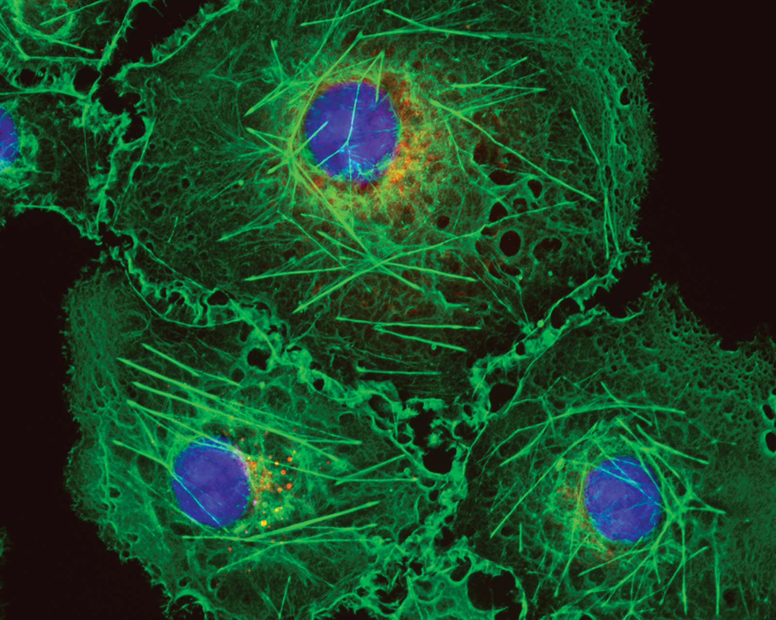
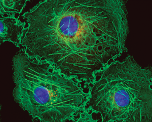
Figure 2: Bovine pulmonary artery endothelial cells labeled with Mito Tracker™ Red CMXRos, Alexa Fluor™ 488 Phalloidin, and DAPI. Magnification is 40×.
Table 1: Excitation and emission peaks of some common fluorophores and genetically expressed fluorescent proteins.

Unlike a fluorophore that is introduced into cells from an external source, the organism of interest intrinsically manufactures genetically expressed fluorescent proteins, thus eliminating stress on the cell and providing a less invasive source of fluorescence labeling. Excitation of fluorophores like TRITC and fluorescence proteins like YFP, mCherry, and RFP require green light for excitation, and subsequently emit red fluorescence.
With LEDs becoming more prevalent as an illumination source, investigators must plan their experiments according to the difference in peak optical power between traditional lamps and LEDs in order to ensure optimization of their filters and to achieve maximum excitation efficiency of their fluorophores. Researchers are now requesting LED replacements equivalent to the full range of the mercury spectrum to be able to enjoy the technological advantages of LEDs, including longer life, lower environmental footprint, smaller size, and reduced price/Watt power benefits. To meet this demand, light source manufacturers must ensure that LEDs used for microscopy illumination can cover the key components of the spectrum including the challenging “green gap” at sufficient power levels.
The Green Gap Challenge
The challenge faced by manufacturers is to design systems that cover the same portion of the spectrum as the mercury arc lamp in order to efficiently excite common fluorophores used in fluorescence studies. The most challenging wavelength band for LED manufacturers to match has been the 540 to 590 nm range, known in the solid-state lighting industry as the green gap (Figure 3). Emission in this region of the spectrum is fundamentally limited by the lack of semiconductor materials to efficiently emit light in this range of wavelengths. LED manufacturers for microscopy and fluorescence excitation have struggled with this for many years, and some have generated innovative solutions to bridge the gap. A range of solutions with varying degrees of success are now available, including LED arrays and wavelength conversion technology such as phosphor materials combined with LEDs. However, many microscopy systems continue to rely on lasers or even mercury arc lamps to efficiently excite fluorophores at these challenging wavelengths.

Figure 3: Mercury lamp spectrum with the LED green gap excitation range highlighted in green.
The Solution
Wavelength conversion with phosphor materials has been used in the lighting and projection industries for several decades. Shorter wavelength light (blue, violet, UV) is absorbed by a material that re-emits light of a longer wavelength via phosphor conversion [Reference Ahn3]. Excelitas Technologies’ LaserLED Hybrid Drive uses patented laser phosphor conversion technology to generate high-power light to fill in the green gap region (Figure 4, Patent US #9,239,133). This system uses high-efficiency blue lasers to excite a phosphor layer, generating a broad peak from 500–600 nm, which can then be filtered to a more specific excitation band depending on the excitation peak of the fluorophore of interest. With increased power in the 500–600 nm region, the exposure time required to obtain a good fluorescence signal or image is dramatically reduced compared to other LED green gap solutions. This translates to higher throughput potential and more efficient sample processing for research laboratories.

Figure 4: Comparison of LED power in the green gap without LaserLED Hybrid Drive (blue line) vs. with LaserLED Hybrid Drive (green line).
To successfully take advantage of these new capabilities, the resulting illumination systems take into account all thermal, electrical, and optical parameters to maximize light conversion and delivery of light to the sample. This solution can be more efficient than other phosphor conversion techniques and was recognized with a Microscopy Today Innovation Award in 2016. With the LaserLED Hybrid Drive, investigators have a full optical spectrum available to excite common fluorescent proteins and fluorophores with one light source.
Power Equivalence
Life science fluorescence imaging and measurements typically involve excitation of a fluorescence molecule, and collection of the emitted fluorescence via a detector, which can provide the user with a quantitative value for the detected emission or can translate this into a camera image. Microscopists typically use a shorter wavelength to excite a fluorophore and view the longer wavelength emitted fluorescence as an image. To evaluate the ability to overcome the green gap under actual imaging conditions, we tested excitation power at the point where fluorophore excitation occurs, that is, at the sample plane of the microscope. The test compared power reaching the sample using a mercury lamp, a LED source, and the LaserLED Hybrid Drive technology.
The LaserLED Hybrid Drive provided power comparable to that of a mercury lamp, demonstrating that this technology can easily replace traditional lamp excitation sources and outperforms other solutions to fill the green gap (Figures 5–7). This provides investigators the opportunity to switch to a technology where short lamp lifetimes and bulb stock and stability are not concerns in completion of imaging and research projects.

Figure 5: Comparison of excitation light power reaching the sample plane on an Olympus BX50 microscope using a 10× objective.

Figure 6: Comparison of excitation light power reaching the sample plane on a Zeiss microscope using X-Cite XYLIS LED, X-Cite 120Q mercury lamp, and a competitor's LED as illumination sources.

Figure 7: Comparison of the spectrum of mercury (blue) with phosphor LED (green) and LaserLED Hybrid Drive technology (red).
Conclusion
Microscopists have struggled with the low power of green LEDs since they first entered the laboratory environment over a decade ago. Since then, technology has advanced dramatically, allowing manufacturers to develop innovative methods for delivering a solution to excite fluorophores in this troublesome green gap region. The Excelitas´ LaserLED Hybrid Drive provides users with superior illumination uniformity and maximum light delivery at all wavelengths. This technology enables investigators to easily switch from mercury, metal halide, or xenon lamps to LED technology and to enjoy the benefits of LED light sources, including long life, stability, lower running costs, and a smaller environmental footprint. Filling in the challenging green gap enables researchers, who are accustomed to traditional lamp technologies, to excite all fluorophores using LED illuminators without compromise.


