1 Introduction
Acceleration of ions by intense laser pulses[Reference Perry, Pennington, Stuart, Tietbohl, Britten, Brown, Herman, Golick, Kartz, Miller, Powell, Vergino and Yanovsky1] relies on using different mechanisms that are distinct in the required target thickness. For micrometre thick foils, target normal sheath acceleration (TNSA)[Reference Wilks, Langdon, Cowan, Roth, Singh, Hatchett, Key, Pennington, MacKinnon and Snavely2] typically dominates. The weak constraints of target foils required for TNSA-based ion sources make this method particularly suitable for repetition rated operation by employing, for example, tape drives for target refreshing. Over the last years, sub-micrometre thin foils have been studied and found to be advantageous in various aspects, e.g., the increased ion flux as well as the reduced Debry and background radiation level. Of course these promising advantages come to the price of less comfortable production of thin targets, the control of their quality and thickness, and also the non-trivial disposal of large quantities.
Over the past decade, diamond like foils[Reference Ma, Liechtenstein, Szerypo, Jung, Hilz, Hegelich, Maier, Schreiber and Habs3] and various kinds of plastic foils have proven well suitable for first, typically single shot based demonstration experiments[Reference Steinke, Hilz, Schnürer, Priebe, Bränzel, Abicht, Kiefer, Kreuzer, Ostermayr, Schreiber, Andreev, Yu, Pukhov and Sandner4, Reference Lee, Park, Cha, Lee, Lee, Yea and Jeong5]. Meanwhile, techniques have been proposed and also realized to supply specific nanometre thin targets which can even be produced on site, i.e., in the focal area of the laser pulse[Reference Poole, Willis, Cochran, Hanna, Andereck and Schumacher6]. Yet there is still sizable effort to produce durable targets off-site, for example for careful characterization prior to an experiment.
Techniques used for producing freestanding thin plastic foils require a number of preparation steps. These include covering a flat material like a silicon wafer or a glass plate with a water soluble sacrifice layer. The film is then covered with the desired foil material. This can be done using different techniques including evaporation, chemical-vapour-deposition (CVD)[Reference Davison and Colquhoun7], filtered cathodic vacuum arc deposition (FCVA)[Reference Aurand, Elkin, Heim, Lommel, Kindler, Tomut, Rödel, Kuschel, Jäckel, Barz and Kuehl8] or spin-coating[Reference Donnet and Erdemir9]. Finally the foils are floated off the substrate in water and stick to the target holder via adhesion.
One standard method to produce Formvar foils is spin-coating[Reference Hall, Underhill and Torkelson10]. Here a solution of Formvar and dichlorethane is dropped on a covered silicon wafer on a fast spinning plate. Due to centrifugal forces, the solution spreads across the plate and the solvent evaporates, leaving a thin layer of plastic behind which can be floated off thereafter.
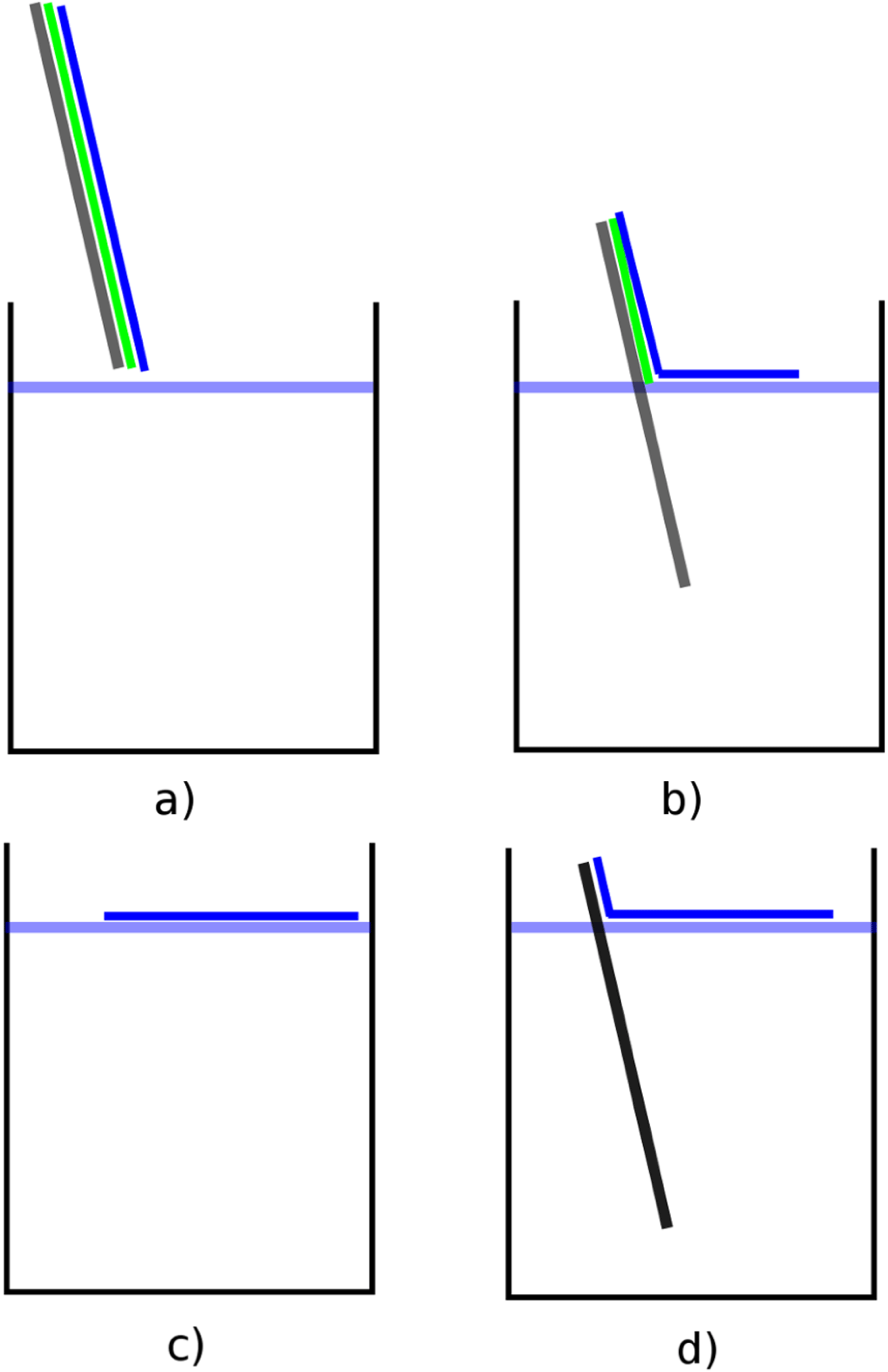
The most time consuming procedures during all of these processes were found to be the deposition and the floating, which take unacceptably long when large quantities of foils are required (see Figure 1).
When restricting our needs to plastic materials, we investigated the droplet method that circumvents floating and shortens the production time significantly, enabling the provision of hundreds of foils per day, and if a constant thickness is required, even in one single process.
Here the plastic is dissolved in a solvent and this solution is then dropped directly on a water surface. The solvent evaporates within a few seconds and the remaining foil can be placed directly on a target holder.

Figure 1. Standard floating process needed for all foil production techniques. (a) After a silicon wafer or glass plate (grey) is covered with a thin water soluble sacrificial layer (green), the desired foil material is placed on it (blue). (b) When slowly floating the wafer, the sacrifice layer dissolves, leaving the foil swimming on the water surface. (c, d) After the whole foil is floated, it is contacted with a target holder where it sticks due to adhesion.
We tested this method for three different plastics – Formvar, polystyrene and cellulose acetate in combination with the solvents dichlorethane, chloroform and acetone.
Cellulose acetate did not produce any foil at all on the water surface with any of those solvents, and the solvent acetone did not show any results at all.
2 Foil characterization
The advantage of direct translation of the foil onto the holes of the target holder complicates their characterization.
While measuring foils on a substrate can be easily investigated optically with confocal and brightfield microscopy, or mechanically with an atomic force microscope (AFM), these methods largely fail for measuring the foils directly on the water surface. Therefore, in order to get comparable results for the thickness determination of the various methods, the foils produced via the droplet method were placed on a flat surface, typically a glass plate or a silicon wafer.
Following first successful tests with a single pipette for dropping the solution onto the water surface, a multichannel pipette has been implemented in order to increase the size of the foil. Here several drops can be released locally independent and simultaneously. This allowed for producing foils with several centimetres in diameter in a single step.
With this tool at hand, a large measurement series was performed in which the concentrations of Formvar and polystyrene – dissolved in dichlorethane and chloroform – have been varied.
To obtain a meaningful statistic, four concentrations (4%, 2%, 1% and 0.5%) were used. For each concentration 10 foils were produced and put on a glass plate with an extension of 76 mm by 26 mm. The foil thickness was measured with a confocal microscope in distinct points separated by 1 cm across the long side of the plate, resulting in 60–70 sampling points for each concentration and solvent.
We note that spectral reflectance is a very useful tool to measure the foil directly on a target holder. When shining white light onto the foil under a certain angle, different thicknesses appear in different colours, just like an oil film on a puddle.
Along with the measurements employing the confocal microscope, we noted the corresponding colours and created a scheme correlating the thickness of the foil to its apparent colour.
We also performed more accurate measurements with the spectral refractometer and found that when using the correct refractive index of Formvar and polystyrene, the results where well in line to within a few nanometres with the results from the confocal measurements.
However, the refractive measurements failed for foils thinner than 50 nm. One possible explanation for this could be the unknown exact dispersion curve for Formvar.
The colours were not only visible on a target holder but also on a foil swimming on the water surface while using a white light at a certain angle behind the foil. Here also, by using the human eye, a correlation between thickness of the foil and its appearance was found.
Table 1. Average values and standard deviation of all thickness measurements for all investigated solvent/plastic combination. Polystyrene and chloroform solutions below 2% did not produce usable foils.

3 Results and discussion
Table 1 summarizes the average values and the standard deviations of the foil thickness calculated from the 60–70 sampling points after evaluating all of the measurements, for each concentration and solvent combination. The standard deviation and the average foil thickness of all 6–7 measuring points was calculated. As an orientation for useful values, a standard deviation below 20% was considered to be desirable for using the foils in laser ion acceleration. The lowest thickness variation resulted from the combining of Formvar and dichlorethane, regardless of the targeted production thickness.
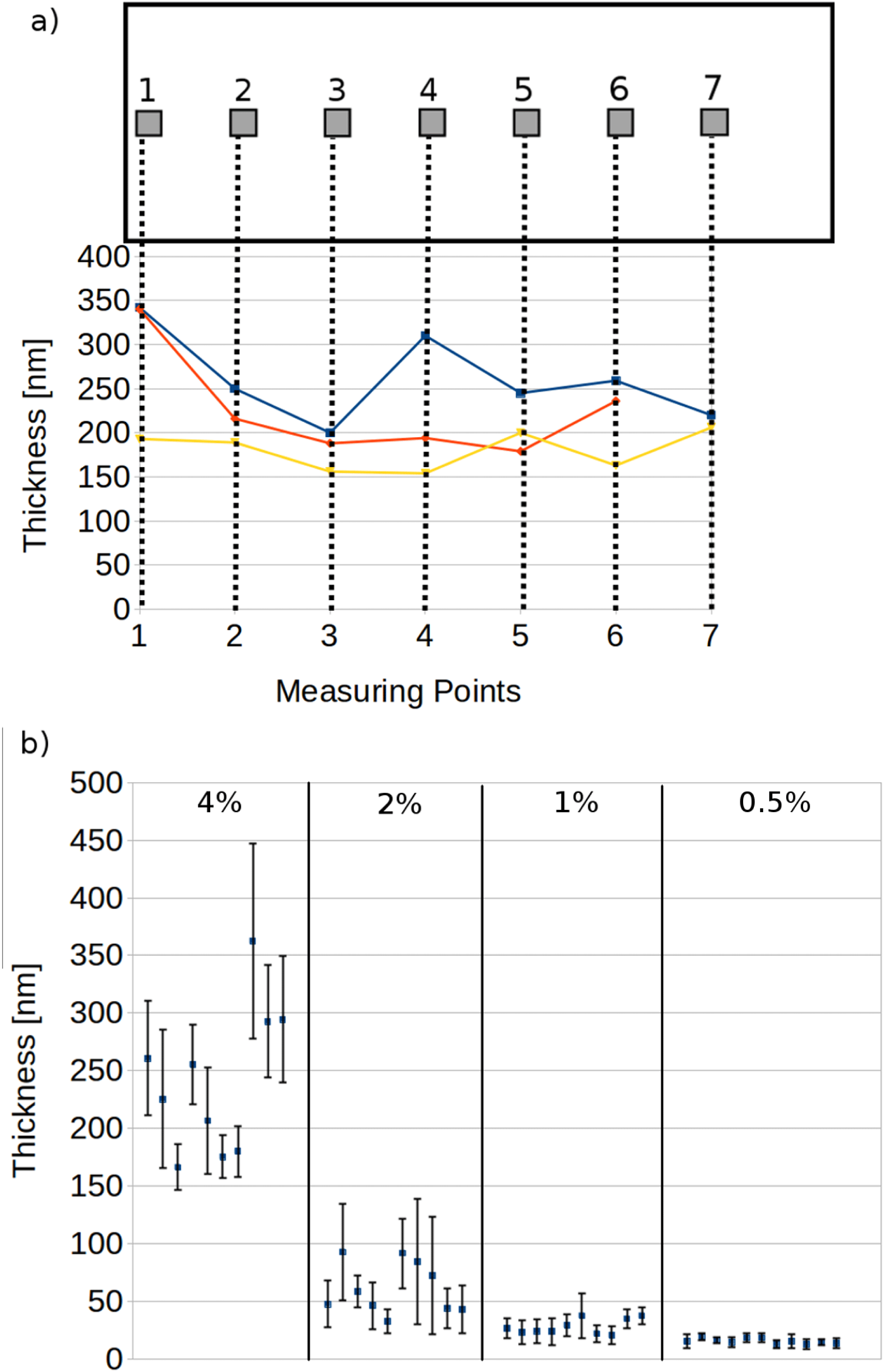
For this combination, we further detail the exemplary case of 4% concentration (see Figure 2(a), highlighted in Table 1).

Figure 2. (a) Sample points on a glass plate (top) as well as three example profiles of foils (bottom) obtained with 4% Formvar in dichlorethane. (b) Average thicknesses and standard deviation for the 10 samples that we prepared for each concentration. Each data point represents the 6–7 measuring points shown in (a).
It becomes apparent that some foils show smaller thickness variations as low as 10% while others reach alarming values of 30% or even more. Such large variations can however be substantially reduced by more careful preselection before mounting them. It is also worth noting that the required transverse size of the foils used in our standard setup is only 30 mm by 16 mm. At this reduced scale the thickness variations will also be reduced.
As mentioned earlier, it is possible to judge on the thickness of a foil floating on the surface of the water and thus possible to choose certain areas with low fluctuations which become obvious to the naked eye.
By applying this simple selection procedure, the results improve considerably.
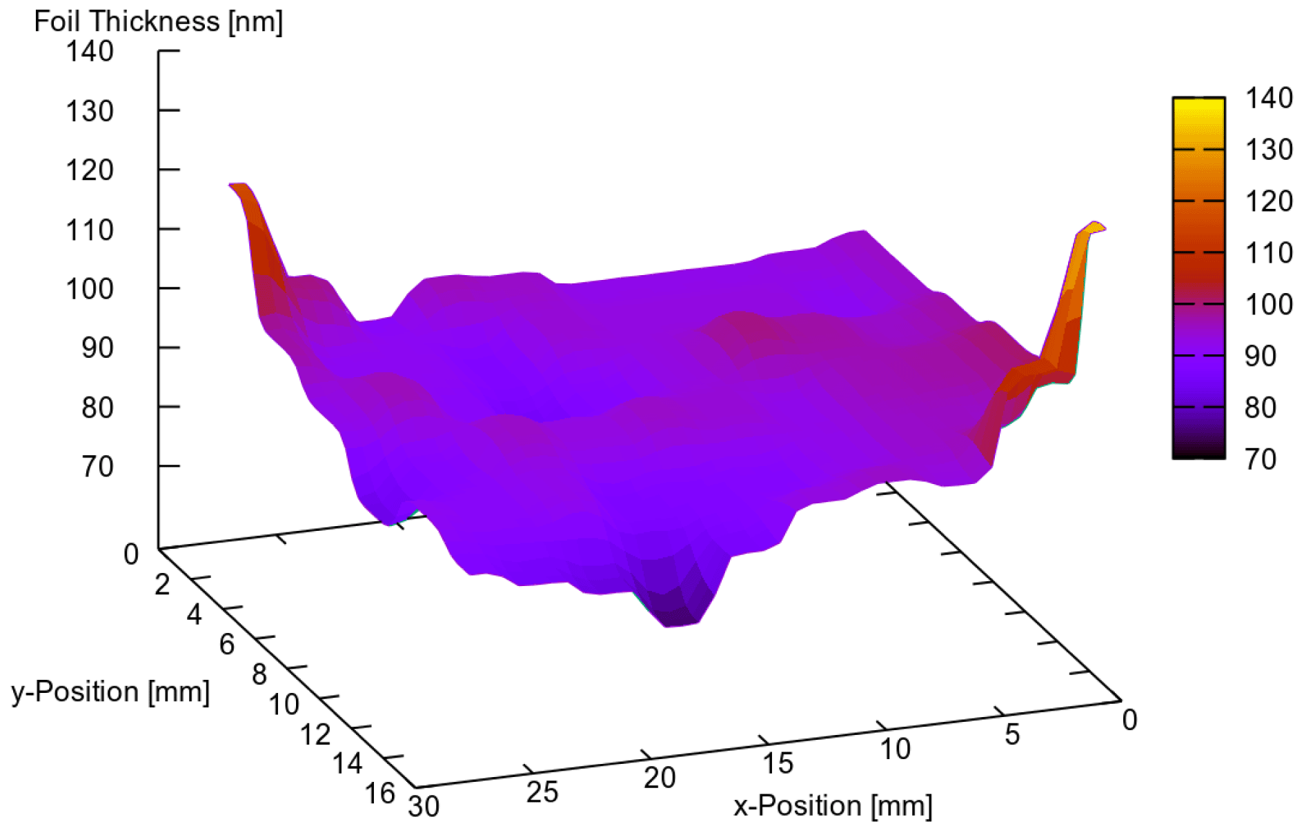
Figure 3 shows the thickness of a sample foil obtained in the same way as before, i.e., 4% Formvar dissolved in dichlorethane, but selected by the described procedure. This time, the measurement has been performed with the refractometer on all sample holes of the target holder. Except for the outer edges, which are typically irrelevant for experiments, the thickness deviation is less than 10%.

Figure 3. Distribution of a target thickness of a foil mounted on a target holder. The thickness was determined on each hole with the spectral refractometer. In the area relevant for experiments the variation does not exceed 10%.
Small thickness variations are certainly desirable, but not the only important parameter nor a guaranty for reproducible condition in experiments[Reference Roth, Blaszevic, Geissel, Schlegel, Cowan, Allen, Gauthier, Audebert, Fuchs, Meyer-ter-Vehn, Hegelich, Karsch and Pukhov11].
As an example, we compare the microscopic pictures of freestanding Formvar and polystyrene foils on out holder in Figures 4(a) and (b).

Figure 4. Two different 100 nm foils on a target holder. The emergence of bubbles can clearly be seen with Formvar (a) while there are no defects in the polystyrene foil (b).
Obviously, the imperfections in Formvar, which were identified as bubbles, will have a tremendous effect on the interaction if hit by the laser pulse.
However, when using those foils in experiment, we have barely had complete fail shots, which is likely due to the fact that the overall area covered by those bubbles is small compared to the overall available target area, and the laser focus is much smaller.
Quantitative estimates will however be important in future campaigns and will guide for developments in which the good parts of the targets need to be identified prior to the laser shot.
It is also interesting to note that these bubbles only occurred in Formvar and their number varied with thickness. Foils thinner than 80–90 nm did not show any, and with increasing thickness the area covered by them reached a maximum at around 180–200 nm. When increasing the thickness further, the number of bubbles reduces again. In polystyrene we did not observe bubbles at all.
But on the other hand, the polystyrene solutions did not work as reliable. Under some condition which is not clear so far, polystyrene does not form a continuous film on the water surface but rather spreads into many small pieces. One possible explanation could be its hydrophobic nature[12] while Formvar is hydrophilic[Reference Yamaji, Fukuda, Nojima and Web13].
More tests will be required to identify the potential of polystyrene and the possibility to also reduce the thickness fluctuations further.
4 Conclusion
We find the well known but rarely employed droplet technique to produce thin films very helpful and efficient for the production of reasonably large quantities of nanometre thin plastic foils. Under the right conditions and with some training, the preparation of thin films with thicknesses in the range of 10 nm to several micrometers are possible. The thickness variation over a cm large area can be pushed to below 10%. We found Formvar to work most reliably from the target production point of view, while polystyrene provided much clearer foils. For now we find the method in general very adequate as it enables target production on demand with a lead time of one day or less. Especially for large quantities, even if different target thicknesses are required, this method proved to be a good alternative to the other established methods in LMU’s target laboratories.
Especially when using an automated target search system[Reference Gao, Bin, Haffa, Kreuzer, Hartmann, Speicher, Lindner, Ostermayr, Hilz, Lehrack, Englbrecht, Seuferling, Gilljohann, Ding, Ma and Schreiber14], the produced targets where shot at 0.5 Hz.
When using the whole target wheel at the ATLAS laser system, this means the 17 target holders with 100 holes each, can be shot within one hour. Even when adding the time to vent and pump the chamber again, no other technique was able to provide this amount of thin solid foil targets in this short period of time.
Acknowledgements
This work was supported by the DFG funded Cluster of Excellence Munich Centre for Advanced Photonics and the Transregio 18.


