Nomenclature
AHorizontal cross-section of the reservoir
BFlow-law coefficient (5.8 x 10⁷ N m–2 s1/3)
f RFriction coefficient for flow in the conduit, taken to be 0.25 (Spring and Hutter, 1981)
gGravitational acceleration (9.8 m s–1)
hReservoir depth
LSpecific latent heat of fusion (3.34 x 10⁵ J kg–1)
lConduit length
mMass melting rate at the conduit wall
p 1Ice-overburden pressure
P wWater pressure at the conduit inlet
QVolume discharge through the conduit
Q INInflow rate to the reservoir
rConduit radius
SCross-sectional area of the conduit (S = πr2 )
uAreal and longitudinal mean flow speed in the conduit
zThickness of the glacier or ice sheet in vicinity of seal
αConduit slope
ρ IDensity of ice (910 kg m–3)
ρ wDensity of water (1000 kg m–3)
TAverage shear stress exerted by the flow on conduit walls
Subscripts
EEquilibrium
IInitial
Introduction
The stability of water flow in the subglacial conduit connected to an ice-marginal reservoir is examined. Sometimes a glacier will dam a stream and create a lake. Subsequent rain and meltwater input may raise the level of the lake until the water dammed above, within or beneath the glacier bursts free. The most spectacular floods are the jökulhlaups that occur in Iceland, which are often associated with volcanic activity (Björnsson, 1974). In the western Canadian Cordillera, Alaska and the Alps (e.g. Post and Mayo, 1971; Haeberli, 1983), outburst flooding has been documented at numerous sites. The conditions leading to outburst flooding are examined in this paper.
The motion of water through a glacier has been studied previously by Röthlisberger (1972), Nye (1976), Spring and Hutter (1981), Clarke (1982) and Walder and Fowler (1994), among others. Each of these authors approaches from a different point of view the problem of water flow through an intraglacial conduit, but all of them consider a very similar mathematical description of the problem. Despite the complexity of water flow in glaciers (Hooke, 1989), most of the authors consider flow through a single, straight conduit.
The objective of this paper is to develop the stability conditions for flow in such a simple glacial conduit. The water is supplied from an ice-dammed lake. We employ a set of widely used differential equations describing water flow in the conduit, make a number of simplifying assumptions and focus the analysis on the necessary conditions for flow stability. We address the following unresolved questions: (a) Can a stable lake exist? (b) If outbursts occur, will they always produce a “single event™ hydrograph as is generally believed? (c) Are there different possible modes of outburst flooding?
Model Description
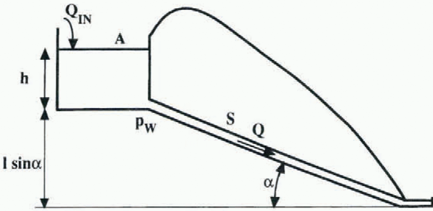
We consider the unsteady flow of water in a straight subglacial conduit with a circular cross-section (Fig. 1). The differential equations governing the physics of the process are based on those presented and discussed by Röthlisberger (1972), Nye (1976), Spring and Hutter (1981) and Walder and Fowler (1994). However, in this paper the focus is not so much on time-dependent solutions as on the system’s stability
Schematic cross-section of the glacier, conduit and reservoir. The symbols are defined in the Nomenclature.
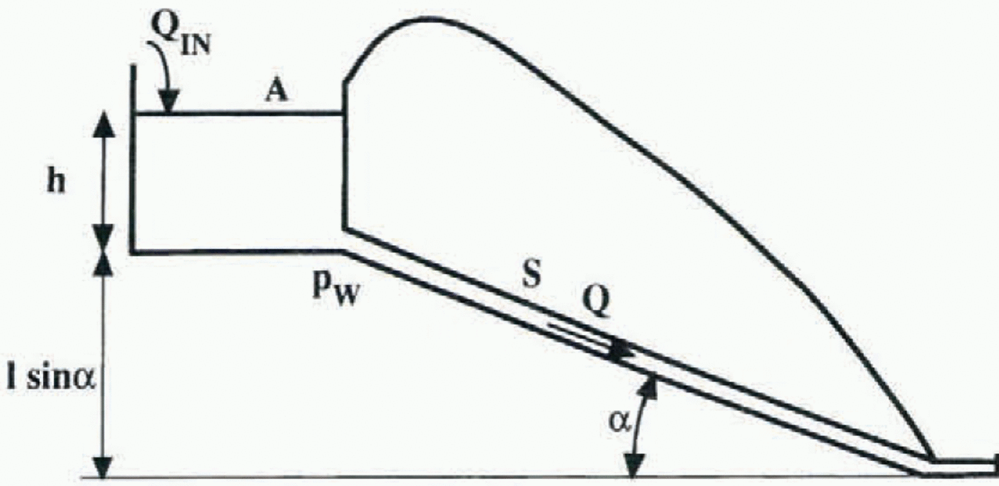
conditions. The model is based on equations describing the conduit area, and the momentum and energy conservation of the flowing water. While, in general, the mathematical description of the flow is specified by a set of partial differential equations, we consider the region of the seal that controls the flow (Clarke, 1982), thereby reducing the problem to a set of time-dependent ordinary differential equations.
The geometrical boundary condition for the conduit specifies that the rate of change of the cross-section is determined by the difference between the rate of melting and the rate of plastic creep (Nye, 1976):

where
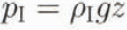
and

We assume that the conduit pressure gradient is constant along its length and that the water pressure at the outlet is atmospheric. Furthermore, we neglect the relatively small change in atmospheric pressure between the conduit outlet and the reservoir surface. It would, however, be straight-forward to modify the outlet pressure to allow for the conduit’s discharge into a lake. The water pressure at the seal is determined by the hydrostatic equation for the reservoir, so, implicitly, we assume the conduit is always full.
For simplicity, the acceleration term is neglected in the momentum equation, which can then be written as a force balance:

Although the acceleration term is neglected, we admit the possibility of velocity changes in the conduit arising as the wall shear stress adjusts to the changing pressure gradient. We assume that the reservoir temperature is equal to the melting point. However, we recognize that the variation of this temperature influences the results, as has been shown by Spring and Hutter (1981) and Clarke (1982). In addition, we have neglected changes of the internal energy of the flowing water. Nye (1976) cautions that the available relations describing heat transfer for forced convection in the conduit may not be valid during flood events, as a result of very high Reynolds number values. Consequently, we further assume that the water temperature remains constant at the freezing point and that all of the frictional heating leads to melting of the conduit wall:

In turbulent pipe flow, there is a quadratic dependence of the wall shear stress on the mean flow speed (Gerhart and others, 1992; Walder and Fowler, 1994):

Substituting Equation (4) into Equation (2), and using the relation Q = Su and S = лr 2, we obtain a relation for the rate of discharge through the conduit:

Substituting Equations (2)–(3) into Equation (1), and using Equation (5), we obtain a relation for the rate of change of the conduit cross-section:

The continuity equation for the reservoir is:

Assuming the horizontal cross-section of the reservoir to be constant, and using Equation (5), one may write Equation (7) as:

Equations (6) and (8), along with initial values of the conduit cross-section and reservoir depth, determine the problem. These equations are similar to the relations derived by Clarke (1982).
In the next section, we will examine the linear stability of these model equations around their equilibria. We will also investigate the time-dependent behaviour of the system. The analysis will be undertaken for both glacier and ice-sheet configurations.
Model Predictions
There are seven physical parameters in Equations (6) and (8). These parameters describe the reservoir geometry, h, A, the rate of inflow to the reservoir, Q IN, the conduit geometry and slope, S, l, α, and the thickness of the glacier or ice sheet in the vicinity of the seal, z. The influence of these parameters on the system’s behaviour will be examined below. Two groups of cases characterized by different conduit slopes will be considered: sin α = 0.1 and sin α = 0.001. These cases were chosen to represent glacier and ice-sheet configurations, respectively. The values of the constants used in the calculations are provided in the Nomenclature.
Flow stability in a glacial conduit
In this subsection, we analyze the linear stability, in the vicinity of the equilibrium solutions, of the non-linear system of Equations (6) and (8) for the high-slope glacier case with sin α = 0.1. To reduce the number of free parameters, we assume that the reservoir is a rectangular box and that its sides are ten times the depth, i.e. A = 10h x 10h. The system’s equilibria are determined by setting the lefthand sides of the model equations to zero. This process yields two algebraic equations in the five equilibrium quantities, h E, Q INE, S E, l E1 and z E. Three of these may be considered independent, while the remaining two can be expressed as functions of these three. We use Equation (6) to determine S E (h E, l E, z E) and Equation (8) to determine Q INE (h E, l E, z E). After linearizing the system of differential equations around this equilibrium, the stability of the linearized system can be determined as a function of the equilibrium glacier thickness in the vicinity of the seal, the equilibrium reservoir depth and the equilibrium conduit length. Because the results show that variation of the conduit length, over a realistic range of values, has little influence on the stability conditions, we assume a fixed conduit length of 10 km in the remaining analysis.
Figure 2shows the results of the local stability analysis as a function of the equilibrium ice thickness and equilibrium reservoir depth. Five types of equilibria can occur: a saddle, an unstable node, an unstable spiral, a stable spiral and a stable node. If an equilibrium is a stable node and a linear system is initially perturbed from the equilibrium, the system returns asymptotically to this equilibrium with time. If an equilibrium is a stable spiral, the system comes back to the equilibrium following harmonic oscillations of decreasing amplitude. On the other hand, if an equilibrium is unstable or a saddle, the system does not return to the equilibrium. For more rigorous definitions of these types of equilibria see, for example, Boyce and DiPrima (1992).
At any point in the plane, the equilibrium conduit cross-section and equilibrium inflow can be calculated from Equations (6) and (8), respectively. Contours of the equilibrium conduit cross-section have been plotted in Figure 2, where these seem to be realistic. The equilibrium cross-section increases with increasing glacier thickness. It is unrealistically large for high thickness and vice versa. The magnitude of the equilibrium reservoir inflow, which would support a steady discharge through the conduit, is related to the conduit cross-section through Equation [5), but is not graphed in Figure 2. In the spiral regimes, the time-dependent solution is periodic of increasing or decreasing amplitude. Contours of the system’s period have been drawn in the stable and unstable spiral regimes where the approach to or departure from equilibrium is oscillatory. The period decreases with increasing thickness, and increases rapidly in the vicinity of the boundary between the stable spiral and stable node (these contours are not shown in Figure 2).
Figure 2suggests that, for realistic values of conduit cross-section, the system is inherently unstable unless the reservoir is very small. Further analysis (not shown) indicates that an increase in the aspect ratio of the reservoir (side to depth) leads to expansion of the unstable region in Figure 2.
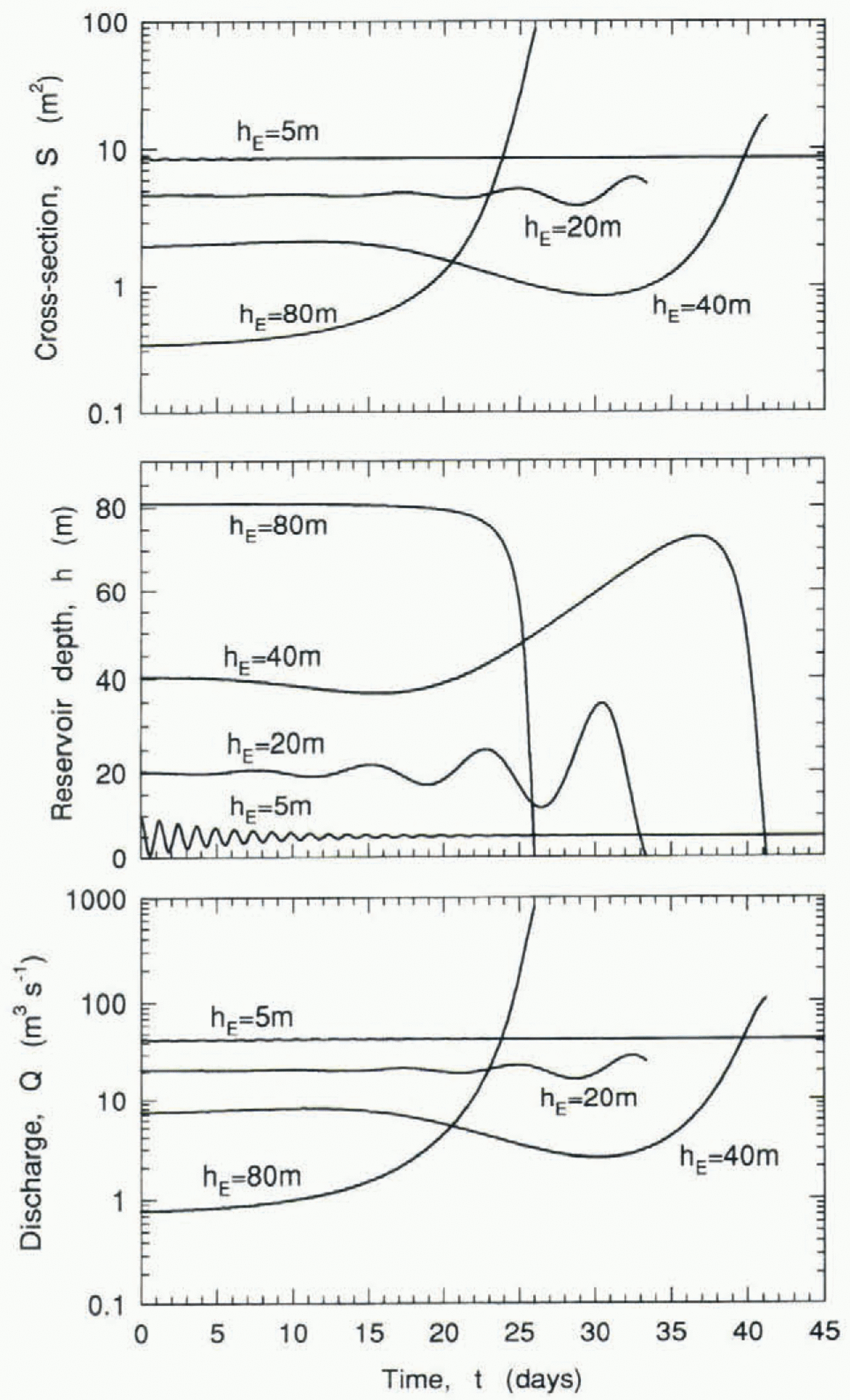
Figure 3shows the time evolution of the conduit cross-section, reservoir depth and discharge from the reservoir for four equilibria shown as points in Figure 2. The system is perturbed from its equilibrium by augmenting the reservoir depth by 1% (except that in the h E = 5 m case the initial reservoir depth is doubled), while leaving the initial conduit cross-section at its equilibrium value. In each case, the equilibrium reservoir inflow is maintained. When the equilibrium is a stable spiral (h E = 5 m; see Fig. 2), the initial perturbation leads to damped oscillations of the system.
Stability regimes of equilibrium water flow in the glacier conduit as a function of the equilibrium glacier thickness, zE, and the equilibrium reservoir depth, hE, with sin α = 0.1, A = 100 hE and lE = 10 km. The heavy solid lines separate the five stability regimes, the dotted lines are contours of oscillation period in the two spiral regimes, and the dashed lines are contours of equilibrium conduit cross-section. The four dots correspond to case-studies in Figure 3.

Time evolution of the conduit cross-section, reservoir depth and discharge through the conduit for four values of the equilibrium reservoir depth. 5, 20, 40 and 80 m. The system is perturbed from equilibrium by increasing the initial reservoir depth by 1% (except for the 5 m case where the initial depth is increased by 100%). The fixed parameters are: sin α = 0.1, A = 100hE2, lE = 10 km and zE = 400 m.
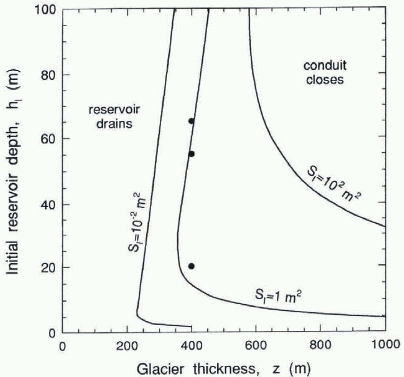
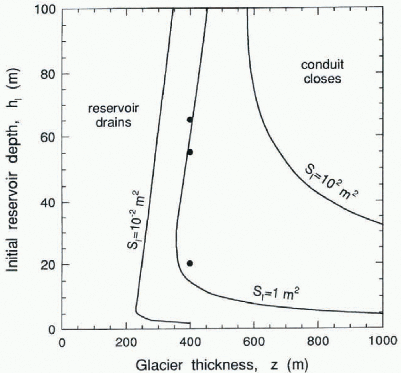
Influence of the initial conduit cross-section on the type of solution (reservoir drainage or conduit closure) as a function of the glacier thickness and initial reservoir depth. The curves, labelled with initial conduit cross-section, separate region in which the conduit closes before the reservoir drains and region in which the reservoir drains before the conduit closes. There is no inflow to the reservoir, QIN 0, and sin α = 0.1, A = 100h12, l = 10km. Three circles are used as case-studies in Figure 5.
When the equilibrium is an unstable spiral (h E = 20 and 40 m), the increasing amplitude of the oscillations over time eventually leads to complete drainage of the reservoir. Results for other cases in this range (not shown) indicate that there seems to be no systematic relation between the moment of reservoir emptying and the ascending or descending phase of the discharge. For larger values of the equilibrium reservoir depth, the ice creep progresses more slowly and the period of the oscillations increases. When h E = 80 m, the equilibrium is an unstable node (see Fig. 2). In this case, the conduit cross-section gradually increases from its initial equilibrium value, and later increases quickly, allowing a rapid discharge of the entire reservoir volume; this is the classic “jökulhlaup”.
Time-dependent water flow in a glacier conduit without inflow to the reservoir
So far we have discussed the system’s behaviour around its equilibria. We have shown that equilibria which occur with realistic parameter values tend to be unstable. We will now consider cases where the initial conditions are not equilibrium values. To keep the problem simple, we assume no inflow to the reservoir, Q IN = 0.
With this restriction, two types of time-dependent solutions can be distinguished: those in which the reservoir drains entirely and those in which the conduit closes with water left in the reservoir. In the following analysis we consider initial conduit cross-section, initial reservoir depth and glacier thickness in the vicinity of the seal to be controlling variables, and assume fixed parameter values as follows: sin α = 0.1, A = 100h I2, l =10 km and Q IN = 0. For a given initial conduit cross-section, the curve separating the region in which the reservoir drains and the region in which the conduit closes is shown in Figure 4. The shape of these curves reflects the existence of two competing processes. For a given conduit size, a deeper reservoir provides a higher hydrostatic pressure in the channel, reducing the creep rate and increasing the likelihood of drainage. The likelihood of drainage also increases with shallow reservoirs because of the small liquid volume and short time required for drainage.
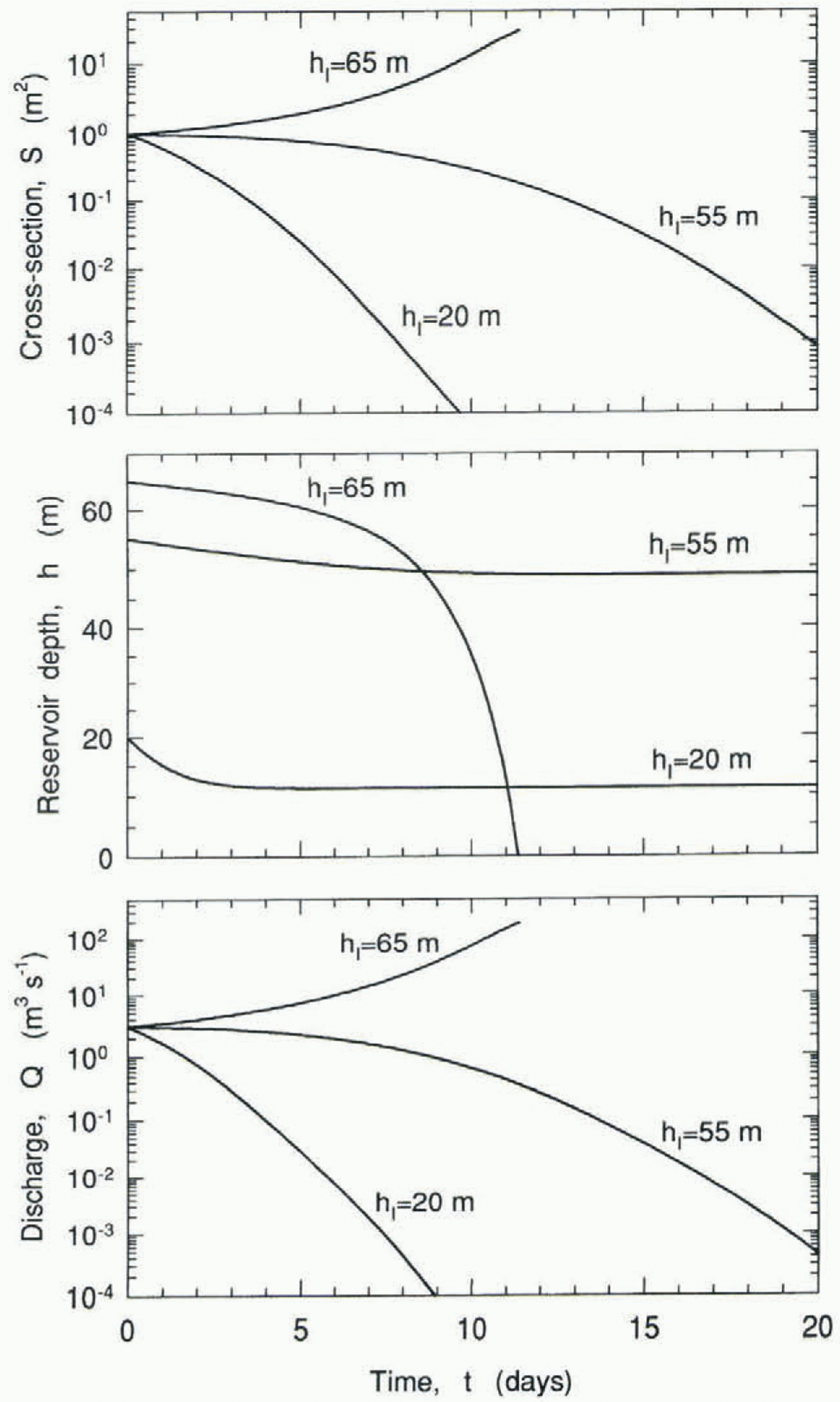
Time-dependent solutions for three initial reservoir depths, 20, 55 and 65 m, are presented in Figure 5. The initial conduit cross-section is 1 m2 and the glacier thickness at the seal is 400 m. With an initial reservoir depth of 20 m, the conduit closes rapidly, the discharge diminishes and the final reservoir depth is 11.0 m. With an initial reservoir depth of 55 m, it takes more time for the conduit to close because of the higher water head. Consequently, the total discharge through the conduit is higher and the final reservoir depth is 48.7 m. A further increase of the initial reservoir depth leads to a qualitatively different solution. When h 1 = 65 m, the rate of conduit wall melting exceeds the rate of ice creep from the beginning. The initial increase in conduit cross-section is followed by an increase in the discharge, which further enhances melting due to frictional dissipation. This
Time evolution of the conduit cross-section, reservoir depth and discharge through the conduit for three initial values of the reservoir depth, 20, 55 and 65 m. For all three cases, the initial conduit cross-section is SI = 1 m2, there is no inflow to the reservoir, QIN = 0, and sin α = 0.1, A = 100 hI2, l=10 km, z = 400 m.
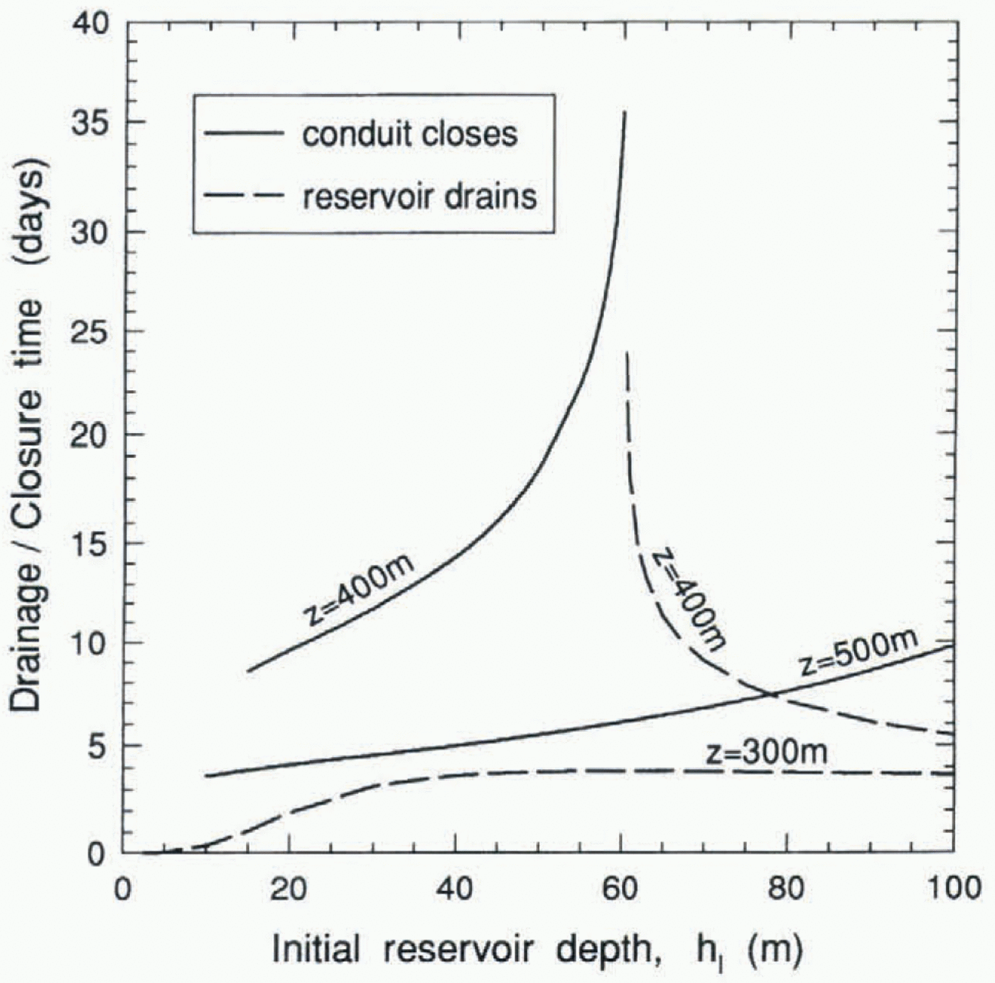
Time required for the reservoir to drain, or for the conduit cross-section to decrease from 1 m2 to 10– m2, as a function of the initial reservoir depth, for three values of the glacier thickness, 300, 400 and 500 m. There is no inflow to the reservoir, QIN = 0, and sin α = 0.1, A = 100 hI2, l = 10 km.
positive feedback leads to a runaway process, and the reservoir drains rapidly, 90% of the volume discharging in about 5 d.
Figure 6shows the time-scale of reservoir drainage and conduit closure as a function of the initial reservoir depth for three glacier thicknesses. When the reservoir drains, the time-scale is defined as the time for complete discharge. For the remaining cases the time-scale is defined as the time needed for the conduit cross-section to decrease to 10–4 m2 from its initial value of 1 m2. When the glacier thickness is 300 m or less, the reservoir always drains (see Fig. 4). The longest drainage time occurs when the initial reservoir depth is around 60 m. An increase in the initial reservoir depth leads to higher water volumes and higher water pressure, the former tending to increase the discharge time and the latter to reduce it. Under these conditions the pressure effect seems to dominate and the drainage time decreases as the initial gradual water discharge is followed by an abrupt opening of the conduit. However, for small values of the initial reservoir depth, h I < 60 m, the volume effect dominates and a reduction in the reservoir depth leads to a corresponding reduction in the drainage time. These two regimes can also be seen for a glacier thickness of 400 m. In the region where the conduit closes, an increase in reservoir depth leads to a rapid increase in the closure time because of the higher water pressure. Similarly the pressure effect leads to a reduction in drainage time in the region where the reservoir drains. When the glacier thickness at the seal is 500 m, similar effects can be observed.
Stability regimes for flow in an ice-sheet conduit as a function of the equilibrium ice-sheet thickness, zE, and the equilibrium reservoir depth, hE, with sin α = 0.001, A = 100hE2 and lE = 50 km. The heavy solid lines separate the five stability regimes, and the dashed lines are contours of the equilibrium conduit cross-section.

Flow stability in an ice-sheet conduit
By scaling up the problem, we have also undertaken an analysis of the stability of conduit flow in an ice sheet. The conduit slope and length and the aspect ratio of the reservoir are taken to be: sin α = 0.001, l = 50 km and A = 100h E2. The five stability regimes and the equilibrium conduit cross-section are shown in Figure 7, as a function of the equilibrium ice-sheet thickness in the vicinity of the seal, and the equilibrium reservoir depth. These results suggest that for a realistic range of cross-sections, with inflow to the reservoir supporting a steady discharge through the conduit, there are both stable and unstable equilibria. For combinations of reservoir depth and ice-sheet thickness outside this range of the cross-section, a realistic equilibrium does not exist.
Conclusions
We have constructed a simple mathematical model of the dynamics of water drainage from a reservoir through a subglacial conduit. An equilibrium condition (steady state), in which the flux through the conduit equals the rate of inflow to the reservoir, may occur only over certain ranges of glacier or ice-sheet thickness and reservoir depth. These equilibria are typically unstable, with a perturbation leading to a catastrophic outburst of water and emptying of the reservoir. The parameter space where discharge may occur periodically with growing amplitude has also been identified. The equilibria are stable only over a very limited range of parameter values. We have also demonstrated that the parameter space where equilibria can occur is narrower for an ice sheet than for a glacier configuration. Finally, for various non-equilibrium combinations of initial reservoir depth, initial conduit cross-section and glacier thickness, the parameter regions associated with reservoir drainage or conduit closure have been elucidated.
In the future, we plan to relax the assumption that the heat from frictional dissipation is transferred instantaneously to the conduit wall to effect melting. The influence of lake temperature, lake geometry and conduit shape on stability should also be examined. We also plan to compare the results of our stability analysis with actual lake-outburst measurements.
Acknowledgements
This research has been supported through Natural Sciences and Engineering Research Council of Canada research grants.