



1. Introduction
Natural plasma engines such as the sun continuously generate enormous magnetic energy with complex field topology, and release this magnetic energy in other forms. In the solar corona region, the linkage and the complexity of field lines, magnetic helicity, is injected through twisting field lines via shear motion of their foot points. This buildup of magnetic helicity is then released through the process of magnetic reconnection, i.e. the rearrangement of magnetic field topology of plasmas, in which magnetic energy is converted to kinetic energy and heat. On the surface of the sun, the process of magnetic helicity injection provides the reconnection sites for oppositely directed field lines to come together to reconnect and energize. In this contribution, we introduce a novel thruster concept, which takes advantage of a similar effect to convert magnetic energy to kinetic energy to produce thrust. In this concept, the reconnection sites are also generated via helicity injection, but by driving current along open field lines rather than twisting them via shear motion. This concept is based on the combination of two key physical effects: (i) magnetic helicity injection and (ii) axisymmetric magnetic reconnection. Significant thrust is generated in the form of plasmoids (confined plasma objects in closed magnetic loops) when helicity is injected into a cylindrical vessel to induce magnetic reconnection. Existing space-proven plasma thrusters, including the ion thruster (Stuhlinger Reference Stuhlinger1964; Choueiri Reference Choueiri2009) and the Hall-effect thruster (Morozov et al. Reference Morozov, Esipchuk, Kapulkin, Nevrovskii and Smirnov1972; Raitses, Smirnov & Fisch Reference Raitses, Smirnov and Fisch2007), electrostatically accelerate ions to exhaust velocities  $v_e$ of tens of kilometres per second to produce thrust. However, for space exploration to Mars and beyond, high-thrust electromagnetic propulsion with exhaust velocities of tens to hundreds of kilometres per second is needed. This new concept, capable of reaching high and variable exhaust velocities, could complement existing designs for such missions.
For efficient use of propellant and propulsion power during space travel, thrusters should have an exhaust velocity similar to the velocity difference  ${\rm \Delta} v$ between the origin and destination celestial bodies. This is quantitatively expressed by the Tsiolkovsky rocket equation
 \begin{equation} {\rm \Delta}{}v = v_e \ln{(m_0 / m_1)} , \end{equation}
where  $m_0$ and $m_1$ are the total mass, including propellant, at the origin and destination, respectively. Equation (1.1) shows that for a given $v_e$ and final mass $m_1$ a linear increase in ${\rm \Delta} {}v$ requires an exponential increase in initial mass $m_0$. If the propellant is fully spent at the destination, the ratio $(m_0 - m_1) / m_0$ is the propellant mass ratio. For conventional chemical thrusters (rockets), the exhaust velocity is limited by the speed of chemical reactions to about $1\text {--}4\ \textrm {km}\ \textrm {s}^{-1}$ (or specific impulse $I_{\mathrm {sp}}$ between 100 and 400 s, where $I_{\mathrm {sp}}=v_e/g_0$, in which $g_0 = 9.8\ \textrm {m}\ \textrm {s}^{-2}$ is the standard gravity). Conventional rockets are therefore efficient only for space missions that can be performed with a ${\rm \Delta} {}v$ budget of about $4\ \textrm {km}\ \textrm {s}^{-1}$, e.g. a mission from low Earth orbit to low Moon orbit. Even for a highly optimized mission from low Earth orbit to Mars, lasting 3–5 months and with a brief launch window every 2–3 years, a ${\rm \Delta} {}v = 6\ \textrm {km}\ \textrm {s}^{-1}$ is needed. With an optimistic assumption of $v_e = 4\ \textrm {km}\ \textrm {s}^{-1}$, (1.1) gives a propellant mass ratio of 78 %, i.e. on launch from low Earth orbit more than three-quarters of the mass is propellant. Thus only Earth's immediate neighbours in our solar system are within reach of conventional rockets.
To surpass the exhaust velocity allowed by limited chemical energy density and reaction rates, electromagnetic propulsion can be used (Goebel & Katz Reference Goebel and Katz2008; Dale, Jorns & Gallimore Reference Dale, Jorns and Gallimore2020). Existing space-proven plasma thrusters can reach a specific impulse  $I_{\mathrm {sp}}$ of about a couple of thousands of seconds (i.e. $v_e$ of about tens of kilometres per second). High-thrust electromagnetic propulsion with $I_{\mathrm {sp}}$ of tens of thousands of seconds is needed to explore the solar system beyond the Moon and Mars, as well as to rendezvous with asteroids, to deflect them if they are on a collision course with Earth, or to capture them for use as a source of water and construction materials to support human presence in space. The unique feature of the plasmoid thruster introduced here is its high and variable $I_{\mathrm {sp}}$, in the range 1000 to 50 000 s, which would be a key advantage for space missions with a large ${\rm \Delta} {}v$, i.e. to Mars and beyond. Here, we show that these high specific impulses could be achieved through continuous production of plasmoids to accelerate ions via a magnetic reconnection process.
Magnetic reconnection, which is ubiquitous in natural plasmas, energizes many astrophysical settings throughout our solar system including the solar corona (solar flares), solar wind, planetary interiors and magnetospheres (see Ji et al. (Reference Ji, Alt, Antiochos, Baalrud, Bale, Bellan, Begelman, Beresnyak, Blackman and Brennan2020) and references therein), as well as throughout our universe, such as flares from accretion discs around supermassive black holes (Ripperda, Bacchini & Philippov Reference Ripperda, Bacchini and Philippov2020). Magnetic reconnection causes particle acceleration to high energies, heating, energy and momentum transport (Ebrahimi & Prager Reference Ebrahimi and Prager2011) and self-organization. The Parker Solar Probe (Fox et al. Reference Fox, Velli, Bale, Decker, Driesman, Howard, Kasper, Kinnison, Kusterer and Lario2016) also provides access to a new frontier for exploring and providing observational evidence of large- and small-scale reconnecting structures in the solar corona. In laboratory fusion plasmas, plasmoid-mediated reconnection has been shown to be important during plasma start-up formation (Ebrahimi & Raman Reference Ebrahimi and Raman2015), nonlinear growth of an internal kink mode (Biskamp Reference Biskamp1986; Günter et al. Reference Günter, Yu, Lackner, Bhattacharjee and Huang2015) as well as transient explosive events such as edge localized modes in tokamaks (Ebrahimi Reference Ebrahimi2017). Here, we demonstrate a practical application of plasmoid-mediated reconnection, namely for space propulsion.
The new type of plasma thruster we are here proposing uses an innovative magnetic configuration to inject magnetic helicity using two annular electrodes biased by a voltage source, thereby inducing spontaneous reconnection via formation of a current sheet, which continuously breaks and generates plasmoids. The concept of biasing open field lines to stretch lines of force and form ‘plasma rings’ (Alfven, Lindberg & Mitlid Reference Alfven, Lindberg and Mitlid1960) was first introduced in the so-called coaxial plasma gun (accelerator) experiments in 1960 (Alfven et al. Reference Alfven, Lindberg and Mitlid1960; Marshall Reference Marshall1960). Since then, coaxial (annular) plasma accelerators have been extensively used and evolved for various applications, including for fusion plasmas to form spheromaks (Jarboe et al. Reference Jarboe, Henins, Sherwood, Barnes and Hoida1983; McLean et al. Reference McLean, Woodruff, Hooper, Bulmer, Hill, Holcomb, Moller, Stallard, Wood and Wang2002; Hsu & Bellan Reference Hsu and Bellan2003) and to fuel tokamaks with compact toroids (Hammer et al. Reference Hammer, Hartman, Eddleman and McLean1988; Brown & Bellan Reference Brown and Bellan1990; Raman et al. Reference Raman, Martin, Quirion, St-Onge, Lachambre, Michaud, Sawatzky, Thomas, Hirose and Hwang1994). The plasma accelerator has also been proposed as a magnetoplasmadynamic thruster for propulsion applications (Cheng Reference Cheng1971; Schoenberg et al. Reference Schoenberg, Gerwin, Henins, Mayo, Scheuer and Wurden1993) and for generating high-velocity plasma jets (Witherspoon et al. Reference Witherspoon, Case, Messer, Bomgardner, Phillips, Brockington and Elton2009). In all these annular plasma accelerators the Lorentz  $\boldsymbol {J} \times \boldsymbol {B}$ force generated by a self-induced magnetic field accelerates plasmas to large velocities. In our new concept the acceleration is instead due to magnetic reconnection (Zweibel & Yamada Reference Zweibel and Yamada2009; Yoo et al. Reference Yoo, Na, Jara-Almonte, Yamada, Ji, Roytershteyn, Argall, Fox and Chen2017). Unlike existing plasma accelerators, the thrust is generated from the acceleration of bulk fluid due to continuous formation of reconnecting plasmoids in the magnetohydrodynamic (MHD) regime. Neither external pulsing nor rotating fields (Chesny et al. Reference Chesny, Orange, Oluseyi and Valletta2017; Bathgate et al. Reference Bathgate, Bilek, Cairns and McKenzie2018) are required here for acceleration through reconnection.
Axisymmetric reconnecting plasmoids are secondary magnetic islands, which are formed due to plasmoid instability. At high Lundquist number, the elongated current sheet becomes MHD unstable due to the plasmoid instability (Biskamp Reference Biskamp1986; Tajima & Shibata Reference Tajima and Shibata1997; Loureiro, Schekochihin & Cowley Reference Loureiro, Schekochihin and Cowley2007; Bhattacharjee et al. Reference Bhattacharjee, Huang, Yang and Rogers2009; Daughton et al. Reference Daughton, Roytershteyn, Albright, Karimabadi, Yin and Bowers2009; Ebrahimi & Raman Reference Ebrahimi and Raman2015; Comisso et al. Reference Comisso, Lingam, Huang and Bhattacharjee2016), an example of spontaneous reconnection. The transition to plasmoid instability was shown to occur when the local Lundquist number  $S = L V_A/\eta$ ( $V_A$ is the Alfven velocity based on the poloidal reconnecting magnetic field, $L$ is the current sheet length and $\eta$ is the magnetic diffusivity) exceeds a critical value (typically a few thousand). Our thruster concept is based on the formation of this elongated current sheet for triggering fast reconnection and plasmoid formation. Effects beyond MHD may also contribute to fast reconnection as the current sheet width ( $\delta _{\mathrm {sp}}$) becomes smaller than the two-fluid or kinetic scales (Cassak, Shay & Drake Reference Cassak, Shay and Drake2005; Ji & Daughton Reference Ji and Daughton2011). However, for thruster application we desire system-size MHD plasmoid formation (with radius ranging from a few to tens of centimetres), where kinetic effects become subdominant for low-temperature plasma (in the range of a few eV to a couple of tens of eV). Here, the MHD plasmoid-mediated reconnection occurs at high Lundquist number (about $10^4$ and above), which is achieved at high magnetic field rather than low magnetic diffusivity (or high temperature). To form a single or multiple X-point reconnection site, oppositely directed biased magnetic field (in the range of 20–1000 G) is injected through a narrow gap in an annular device. We find that the plasmoid structures demonstrated in resistive (or extended) MHD simulations produce high exhaust velocity and thrust that scale favourably with applied magnetic field. It will be shown that the fluid-like magnetic plasmoid loops continuously depart the magnetic configuration about every $10 \ \mathrm {\mu } \textrm {s}$ with Alfvenic velocities in the range of 20 to $500\ \textrm {km}\ \textrm {s}^{-1}$, and the thrust does not ideally depend on the mass of the ion species of the plasma.
2. Schematics of the thruster
Figure 1 shows the main parts of the reconnecting plasmoid thruster in an annular configuration. Magnetic helicity injection starts with an initial injector poloidal field ( $B^{\mathrm {inj}}_P$, in blue, with radial, $R$, and vertical, $Z$, components), connecting the inner and outer biased plates in the injector region. Gas is injected and partially ionized by applying an injector voltage $V_{\mathrm {inj}}$ of a few hundred volts between the inner and outer plates (indicated by numbers 1 and 2), which also drives a current $I_{\mathrm {inj}}$ along the open magnetic field lines. Plasma and open field lines expand into the vessel when the Lorentz force $J_{\mathrm {pol}} \times B_{\phi }$ exceeds the field line tension of the injector poloidal field. The azimuthal ( $\phi$) field shown here, $B_{\phi }$, is generated through injector current ( $I_{\mathrm {inj}}$) alone (by applying $V_{\mathrm {inj}}$), or can be provided externally. Plasma formation through electron impact ionization has been widely used by plasma accelerators and other helicity injection experiments (Jarboe et al. Reference Jarboe, Henins, Sherwood, Barnes and Hoida1983; Hammer et al. Reference Hammer, Hartman, Eddleman and McLean1988; Brown & Bellan Reference Brown and Bellan1990; Raman et al. Reference Raman, Martin, Quirion, St-Onge, Lachambre, Michaud, Sawatzky, Thomas, Hirose and Hwang1994; McLean et al. Reference McLean, Woodruff, Hooper, Bulmer, Hill, Holcomb, Moller, Stallard, Wood and Wang2002; Hsu & Bellan Reference Hsu and Bellan2003; Raman et al. Reference Raman, Jarboe, Nelson, Izzo, O'Neill, Redd and Smith2003; Witherspoon et al. Reference Witherspoon, Case, Messer, Bomgardner, Phillips, Brockington and Elton2009; Raman et al. Reference Raman, Mueller, Jarboe, Nelson, Bell, Gerhardt, LeBlanc, Menard, Ono and Roquemore2011). The conventional Townsend avalanche breakdown theory is applicable for coaxial helicity injection experiments (Hammond, Raman & Volpe Reference Hammond, Raman and Volpe2017; R. Raman, Private communication on helicity injection experiments on HIT-II and NSTX, 2020), a configuration similar to the thruster proposed here.
A schematic of (a) the vertical cross-section and (b) the entire domain of the reconnecting plasmoid thruster. In an annular configuration, injected poloidal field  $B^{\mathrm {inj}}_P$ (blue circle) is generated by poloidal field injector coil ( $I$), while current ( $I_{\mathrm {inj}}$) is pulled along open field lines by applying $V_{\mathrm {inj}}$. Numbers 1 and 2 show inner and outer injector biased disc plates, respectively, separated by the injector gap. All the axisymmetric poloidal coils $(I, D, S1, S2)$ are located to the left of these plates. For formation of an elongated current sheet to induce spontaneous reconnection, the detachment coil $D$ and shaping coils $S1$ and $S2$ are also energized to generate the poloidal fields $B^D_P$ and $B^S_P$ (shown in red in (b)).
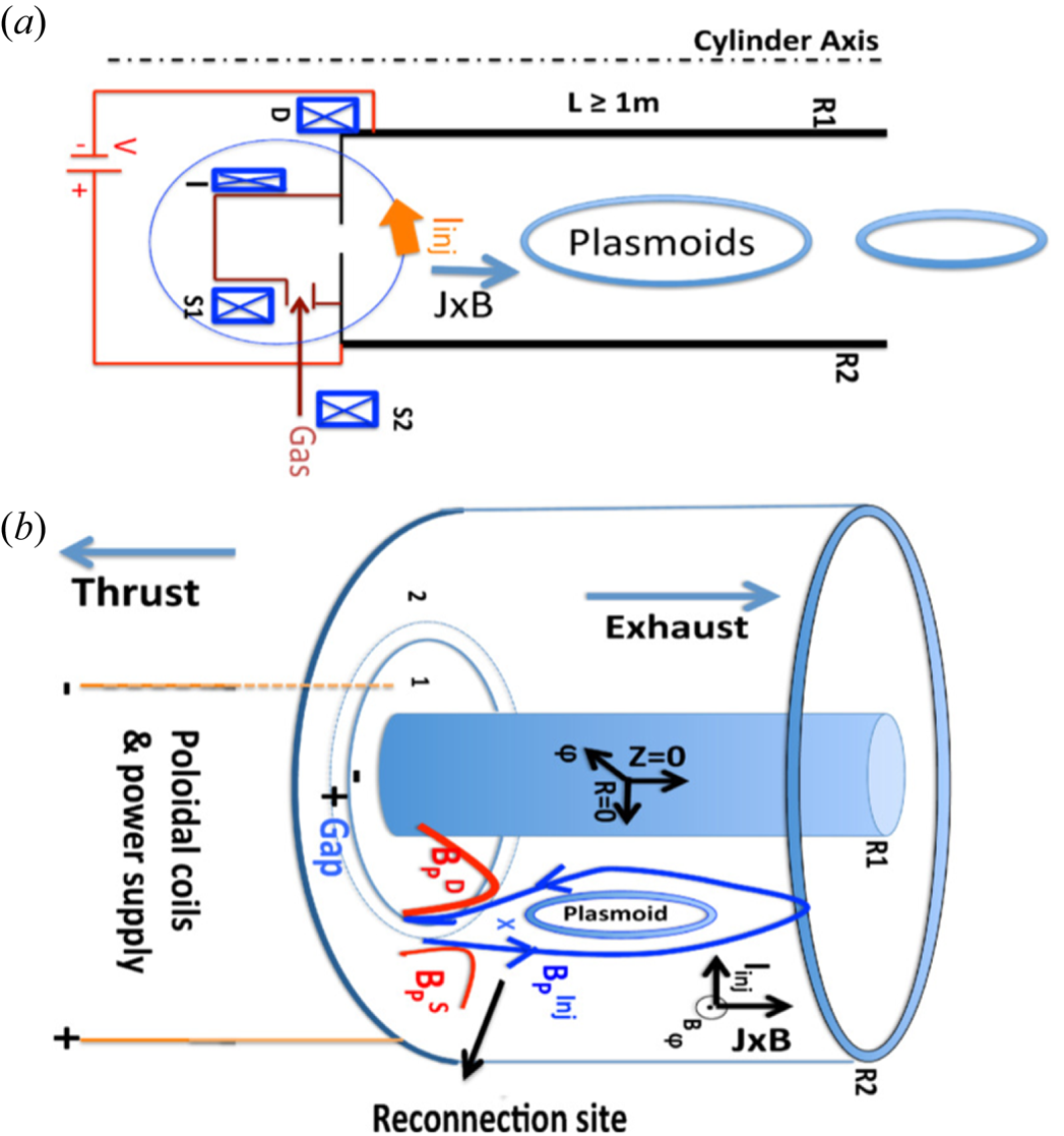
Up to this point the concept of magnetic helicity injection through the linkage of the injected poloidal field and injected azimuthal field from poloidal current along the open field lines is similar to that of conventional annular accelerators. However, at this stage we introduce the new concept of plasmoid-mediated reconnection for generating thrust, i.e. through forming a vertically elongated (along  $Z$) azimuthal current sheet ( $J_{\phi }$), which contributes to the Lorentz force. To continuously form a current sheet at the reconnection site, the detachment and shaping poloidal fields $B_P^D$ and $B_P^S$ (shown in figure 1b and produced by the $D$,
$D$,  $S1$ and $S2$ coils) are utilized and have an instrumental role for this thruster concept. These coils can be effectively used to strongly and radially squeeze the injector poloidal field to cause oppositely directed field lines in the $Z$ direction (shown in blue arrows at the reconnection site) to reconnect. To form this reconnection site, the currents in the detachment and shaping coils are in the opposite direction to the current in the injector coil, and the detachment-coil current is of magnitude equal to or larger than the injector-coil current. As a result, azimuthally symmetric system-sized plasmoid structures are detached and ejected to produce thrust.
3. Global extended MHD simulations
We perform time-dependent extended MHD simulations of the thruster using the NIMROD code (Sovinec et al. Reference Sovinec, Glasser, Gianakon, Barnes, Nebel, Kruger, Schnack, Plimpton, Tarditi and Chu2004), which is a community code supported by DOE, and has been extensively used and validated for various helicity injection fusion experiments (Bayliss, Sovinec & Redd Reference Bayliss, Sovinec and Redd2011; Hooper et al. Reference Hooper, Bulmer, Cohen, Hill, Holcomb, Hudson, McLean, Pearlstein, Romero-Talamás and Sovinec2012; Morgan, Jarboe & Akcay Reference Morgan, Jarboe and Akcay2019), including start-up helicity injection experiments for spherical tokamaks (NSTX and NSTX-U) (Ebrahimi et al. Reference Ebrahimi, Hooper, Sovinec and Raman2013, Reference Ebrahimi, Raman, Hooper, Sovinec and Bhattacharjee2014; Hooper et al. Reference Hooper, Sovinec, Raman, Ebrahimi and Menard2013; Ebrahimi & Raman Reference Ebrahimi and Raman2016). We model coil currents that produce the needed injected field for the reconnection site. Simulations are performed for a constant-temperature model (pressure is not evolved in time) with constant-in-time poloidal-field coil currents. We have optimized and varied extensively the current in the poloidal coils ( $I,D, S1, S2$) to form a reconnection site and a current sheet. Our extended MHD model consists of combined Faraday and generalized Ohm's laws and the momentum equation:
 \begin{gather} \rho \left(\frac {\partial \boldsymbol{V} }{ \partial t } + \boldsymbol{V}\boldsymbol{\cdot} \boldsymbol{\nabla} \boldsymbol{V}\right) = \boldsymbol{J} \times \boldsymbol{B} - \boldsymbol{\nabla}\boldsymbol{\cdot} \varPi, \end{gather}
 \begin{gather}\frac {\partial \boldsymbol{B} }{ \partial t } = - \boldsymbol{\nabla} \times \left( -\boldsymbol{V}\times \boldsymbol{B} + \eta \boldsymbol{J} + \frac{1}{ne} \boldsymbol{J}\times \boldsymbol{B} + \frac{m_e}{ne^2} \frac{\partial \boldsymbol{J}}{ \partial t}\right), \end{gather}
where  $\boldsymbol {V}$ is the centre-of-mass velocity and $\rho$ is the mass density of a plasma with magnetic field $\boldsymbol {B}$ and current density $\boldsymbol {J}$. The stress tensor ( $\varPi$) is treated as $-\rho \nu \nabla ^2 \boldsymbol {V}$ or $-\rho \nu W$, where $\nu$ is the kinematic viscosity and $W$ is the rate of strain tensor. In all simulations, the kinematic viscosity is chosen to give Prandtl number $Pm = \eta /\nu = 2 \text {--} 7.5$. The magnetic diffusivities used in the simulations ( $\eta =8\text {--}32\ \textrm {m}^2\ \textrm {s}^{-1}$) are equivalent to constant low temperatures of $T_e \approx 5 \text {--}14\ \textrm {eV}$, according to the Spitzer resistivity relation ( $\eta ~(\textrm {m}^2\ \textrm {s}^{-1}) = 410 T^{-3/2}\ (\textrm {eV})$). A constant electric field is applied across the narrow injector gap (located between the two injector plates $R=0.54\text {--}0.57\ \textrm {m}$, shown in figure 2). Perfectly conducting boundary conditions with no slip are used, except at the injector gap, which has a normal $E\times B$ flow, where a constant-in-time electric field is applied (Ebrahimi et al. Reference Ebrahimi, Hooper, Sovinec and Raman2013; Hooper et al. Reference Hooper, Sovinec, Raman, Ebrahimi and Menard2013; Ebrahimi Reference Ebrahimi2016). We use a poloidal grid with $45 \times 90$ sixth-order finite elements in a global $(R,Z)$ geometry and azimuthal mode numbers ( $n_{\phi }$) up to 22 modes. A uniform number density $(n)$ of $4 \times 10^{18}\ \textrm {m}^{-3}$ for a deuterium or helium plasma is used. Simulations are performed with various coil currents in a straight plasma domain configuration, shown in figure 1, in a thruster channel with inner and outer radii of $R_1=0.21$ m and $R_2=0.85$ m, with the injector plates (1 and 2, shown in figure 1) located at $Z=-0.8\ \textrm {m}$. In general the results do not vary with the axial length of the thruster within the range 1–2 m investigated, and with the angle of the lower injector plates with the side walls ( $90^{\circ }$ and $145^{\circ }$). The locations of the coils are adjusted for simulations performed in different domain sizes. In the simulations shown in figures 3 and 4, the injector ( $I$), detachment ( $D$) and shaping field $(S1, S2)$ coils are located at $R = 0.52$, 0.31, 0.76, 1 m and $Z = -1$, $-0.82$, $-1.05$, $-0.81$ m, respectively. Fields $B_P^D$ and $B_P^S$ are static and assumed to have penetrated through the bounding surfaces.
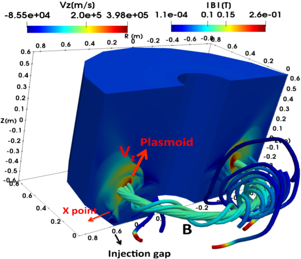
The formation of momentum-carrying plasmoid during three-dimensional global extended (two-fluid) MHD simulations. The computational domain and the poloidal coil configurations are the same as the schematics in figure 1. Plasmoid ion (helium) velocity  $V_z$ is seen in the poloidal ( $R$–
$R$– $Z$) cross-section. The velocity structure remains azimuthally symmetric. Following of the magnetic field line shows a closed magnetic loop associated with the plasmoid formation during reconnection.
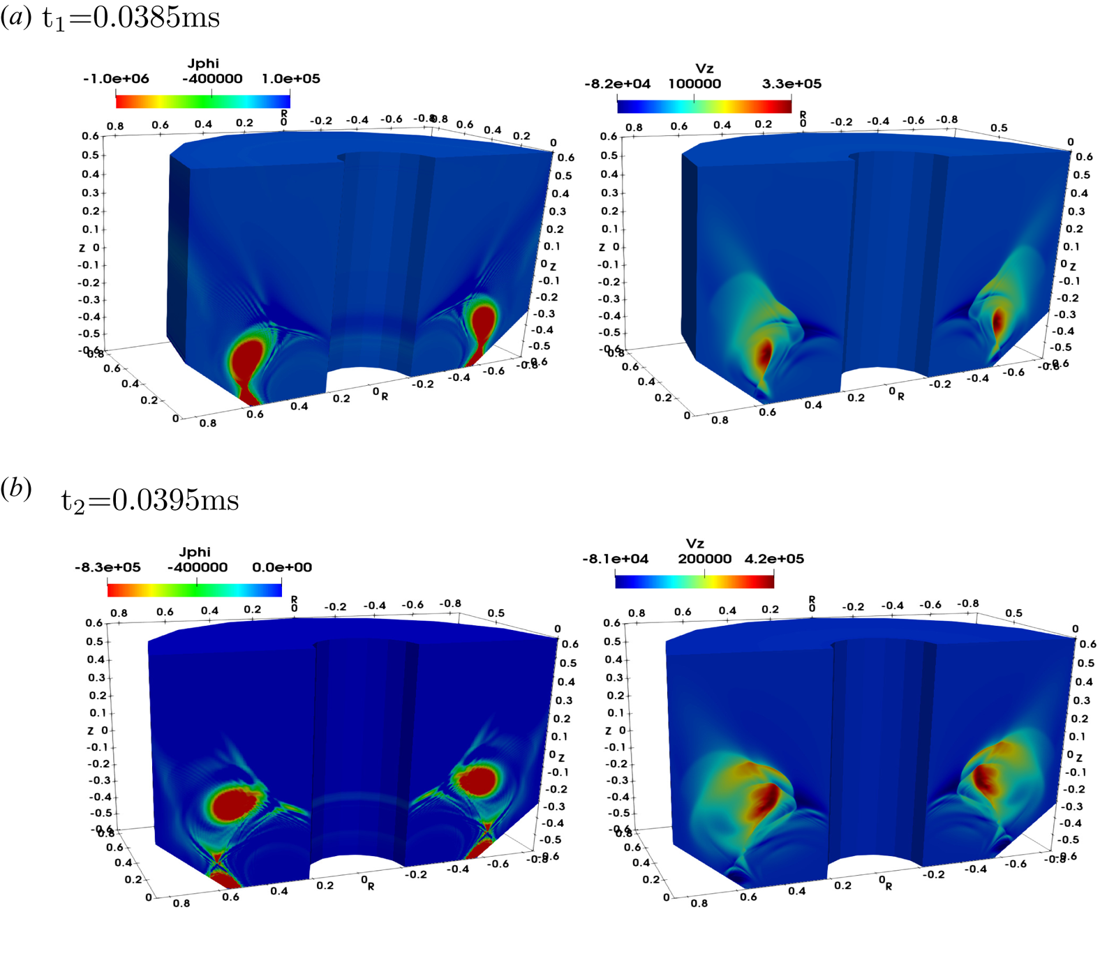
Current density ( $\textrm {A}\ \textrm {m}^{-2}$) and axial velocity $(\textrm {m}\ \textrm {s}^{-1}$) for the same two-fluid simulation shown in figure 2, at the two times (a) ${t_1}$= 0.0385 and at $1\ \mathrm {\mu }\textrm {s}$ later at (b) ${t_2}$=0.0395.
Poloidal  $R$–
$R$– $Z$ cut of (a) injected vertical magnetic field $B_z$ (T) and (b) generated azimuthal field $B_{\phi }$ (T) at $t=0.044\ \textrm {ms}$ during the helicity injection (black arrows show the oppositely directed reconnecting $B_z$ field at the reconnection site). Azimuthal current density $J_{\phi }$ ( $\textrm {A}\ \textrm {m}^{-2}$) with (c) MHD and (d) two-fluid model (from same simulation as results in figure 2). Red arrows show reconnecting plasmoids.

A cut of the general computational domain of annular geometry is shown in figure 2. In this simulation we have used a two-fluid model, i.e. using both the Hall term and electron inertia terms in equation (3.2) with an increased electron mass ( $m_i/m_e=73$). The exhaust vertical velocity of azimuthally symmetric plasmoids reaches about $400\ \textrm {km}\ \textrm {s}^{-1}$ (figure 2). Most of the momentum is along the large plasmoid (and current sheet). The Alfvenic-type outflows obtained here ( $V_A$ for this case using $B_z=0.08$ is about $460\ \textrm {km}\ \textrm {s}^{-1}$) are due to spontaneous reconnection and the plasmoid ejection. In the two-fluid model, fast reconnection is caused by the Hall current, which is a signature of the decoupling of electron and ion motions at scales below the ion skin depth $d_i$ ( $d_i=c/\omega _{pi}$, where $c$ is the speed of light and $\omega _{pi}$ is the ion plasma frequency). Here $d_i$ is calculated to be relatively large, about 11 cm. Current density and axial velocity for the two-fluid simulation at two times are also shown in figure 3. The formation of the single $X$-point during Hall reconnection at ${t_1}$ and then the subsequent ejection of a large plasmoid at ${t_2}$ with large exhaust velocity of $420\ \textrm {km}\ \textrm {s}^{-1}$ are observed. The two-fluid results in terms of exhaust speed of plasmoids during reconnection are similar to the resistive MHD model (shown below). We therefore present below more detailed results from resistive MHD simulations to focus on the plasmoid-mediated reconnection for this concept.
For this thruster concept, we start with an initial injector poloidal field ( $B^{\mathrm {inj}}_P$) with a very narrow footprint (where open field lines intersect the inner and outer plates) to form a reconnection site. Poloidal $R$–
$R$– $Z$ cuts of the oppositely directed injected reconnecting field ( $B_z$), which provides the primary reconnection site, and the azimuthal field, which is intrinsically generated by the poloidal injector current in the injection region, are shown in figures 4(a) and 4(b), respectively. As the injector voltage is applied (by ramping $V_{\mathrm {inj}}$ from zero to about 200 V), the generated azimuthal field could reach as high as 2000 G (figure 4b), which causes the injector poloidal field to start expanding in the thruster channel. As the field is expanded in the domain, the static fields $B_P^D$ and $B_P^S$ radially pinch the injector field around the injector gap to form a primary exhaust reconnecting current sheet, as shown in blue (figure 4c). The plasmoid instability is here triggered at local Lundquist number $S \sim 12\,000$ (based on $B_z \sim 500\ \textrm {G}, L = 0.5\ \textrm {m}$ and $\eta =16\ \textrm {m}^2\ \textrm {s}^{-1}$). The formation of a plasmoid along the current sheet is seen in figure 4(c,d) (in blue). For comparison, the exhaust current density for the two-fluid simulations (shown in figure 2) with single $X$-point Hall reconnection topology (Huang, Bhattacharjee & Sullivan Reference Huang, Bhattacharjee and Sullivan2011) is shown in figure 4(d). We have also performed two-fluid simulations at smaller $d_i$ (of about 2 cm at higher density), and then recover the elongated single-fluid current sheet.
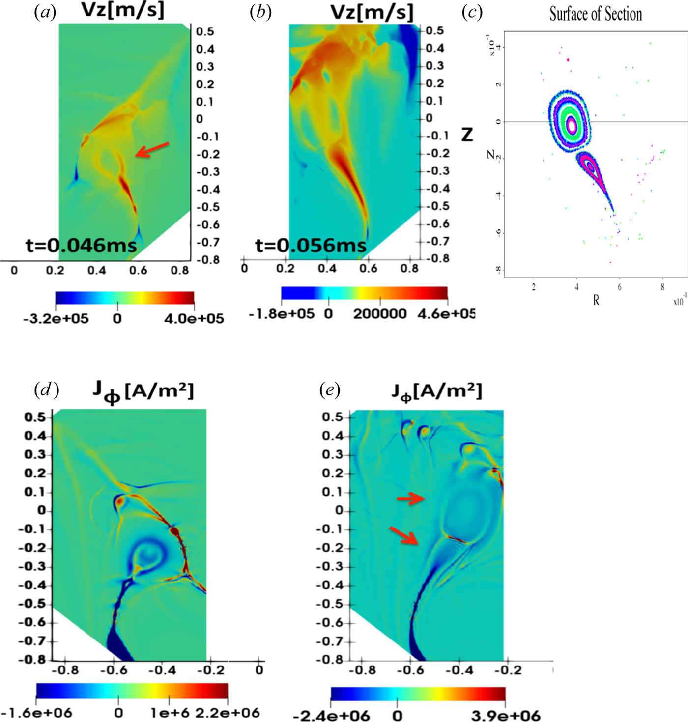
The formation of a large plasmoid with exhaust outflow that reaches as high as  $V_z = 400\ \textrm {km}\ \textrm {s}^{-1}$ around the reconnection region at later time $t=0.046\ \textrm {ms}$ is shown in figure 5. The maximum exhaust velocity is mainly along the current sheet and the plasmoid (as can be seen in figure 5a,b) and exceeds the visco-resistive outflows of the MHD Sweet–Parker (S–P) model, $V_{\textrm {out}}/V_{A(\mathrm {pol})} = 1/\sqrt {1+Pm} \sim 170\ \textrm {km}\ \textrm {s}^{-1}$ (where $V_{A(\textrm {pol})} = B_{\textrm {in}(z)}/\sqrt {\mu _0 \rho }$). The continuous spontaneous breaking of the current sheet and the subsequent formation of current-carrying magnetically self-confined loops, i.e. plasmoids, occur at later times (figure 5b,c), as long as the voltage is applied. As seen from the Poincaré plot in figure 5(c), two large plasmoids are formed. At this later time, as the first plasmoid is already ejected, the open field lines start to close again and a large-volume closed field line in the form of a second plasmoid is formed and departs the device with a high outflow velocity of about $460\ \textrm {km}\ \textrm {s}^{-1}$ (figure 5b). The maximum outflows are both along the exhaust current sheets (shown in blue in figure 5d,e) in the form of outflow jets, as well as along the plasmoids. We should note that small-scale plasmoids are also formed along a current sheet (seen in red colour in figure 4c) above the primary exhaust current sheet. Although these also contribute to positive large vertical outflows, they are less important, as they are not directly connected to the injector plates. It is important to note that although all the simulations above are three-dimensional (by including 21 non-axisymmetric ( $n_{\phi }\neq 0$) modes), all the structures during nonlinear evolution shown in figures 2–5 remain azimuthally symmetric (axisymmetric). In these simulations, the time scale for the cyclic ejection of large-scale axisymmetric plasmoids is around $10\ \mathrm {\mu }\textrm {s}$ (4–5 Alfven transit times). This time scale is much shorter for any non-axisymmetic disturbance to growth to large amplitudes.
Poloidal ( $R$–
$R$– $Z$) cuts of vertical flow velocity at (a) $t=0.046\ \textrm {ms}$ and (b) $t=0.056\ \textrm {ms}$; (c) Poincaré plot. Plasmoid ejection is shown by the red arrow. Axisymmetric azimuthal current densities at (d) $t=0.046\ \textrm{ms}$, and (e) $t=0.056\ \textrm{ms}$.
4. Scaling of the exhaust velocity with reconnecting field
To further examine the variation and the dependence of the exhaust velocity on the injected field ( $B_z$), we have performed simulations with two different magnetic configurations in which we have varied the coil currents. We should note that in all the simulations presented above the azimuthal field is intrinsically generated. Here we also use an external azimuthal guide field of about 7000 G, which would not affect the scaling, as we only use the reconnecting $B_z$ field in figure 6. The first configuration is shown in figure 6 in blue triangles at $B_{\mathrm {rec}} =400\ \textrm {G}$ (case 1), which results in $V_z =300\ \textrm {km}\ \textrm {s}^{-1}$. To scan over $B_{\mathrm {rec}}$, we first reduce the detachment coil current (which gives $B_z= 200\ \textrm {G}$, case 2), and then we reduce the current in all the coils by 50 % (giving $B_z= 130\ \textrm {G}$, case 3), and much reduced outflow velocity of about $60\ \textrm {km}\ \textrm {s}^{-1}$. In the second configuration, we use a much higher ratio of the two shaping coil currents, but with the same injector and detachment coil currents as the first configuration. The dependency of the outflow on $B_{\mathrm {rec}}$ for the cases in this configuration is also shown (by red diamonds) in figure 6. We also compare the outflows (maximum flows along the exhaust current sheet) obtained in the simulations with the slow S–P type reconnection model outflows in a visco-resistive MHD plasma (with $Pm=7.5$). Using $B_z$ from the simulations, figure 6 shows the calculated outflows based on the local S–P model (black triangles) versus $B_z$. It is shown that the outflows from MHD simulations do favourably scale with $B_z$, are higher (more than double) compared to the slow S–P velocities and are due to the fast plasmoid-mediated reconnection. It is therefore found that the exhaust velocities in these magnetic configurations are Alfvenic-type reconnecting outflows as they are strongly associated with the strength of $B_{\mathrm {rec}}$.
Maximum exhaust velocity obtained from simulations versus reconnecting magnetic field for two magnetic configurations with different ratio of poloidal coil currents. The dashed black line with triangles shows the theoretical S–P scaling.

5. Thrust and the thrust to power ratio
Because the plasmoids are ejected at the Alfven velocity, the expression for the thrust (Lovberg Reference Lovberg1971) becomes  $F = \rho V_A^2 A$, where $A$ is the area of the plasmoid cross-section. Notably, the thrust then does not depend on $\rho$, and it scales as the magnetic field squared ( $B^2$). For example, for plasmoids with radius 10 cm (as in figure 3d) and reconnecting field of $B=800\ \textrm {G}$, the calculated thrust is about 50 N, taking into account a duty cycle of about 33 % (i.e. the distance between two consecutive plasmoids is twice the plasmoid length). The input power is given by $P_{\mathrm {inj}}= I_{\mathrm {inj}} \, V_{\mathrm {inj}}$, where $I_{\mathrm {inj}} = 2{\rm \pi} rB_{\phi }/\mu _0$. In general $I_{\mathrm {inj}}$ could vary from a few to a few hundred kiloamps. In our simulations, $I_{\mathrm {inj}}$ is about 100 kA (equivalent to $B_{\phi }\sim 500\ \textrm {G}$), corresponding to about 10 MW of power. For this unoptimized high-power case (with a thrust of 50–100 N), the ratio of thrust over power is thus about $5\text {--}10\ \textrm {mN}\ \textrm {kW}^{-1}$. We have not yet performed a systematic optimization, but tentatively the optimal parameter range for this new thruster will be $I_{\textrm {SP}}$ (specific impulse) from 2000 to 50 000 s, power from 0.1 to 10 MW and thrust from 1 to 100 N. It would thus occupy a complementary part of parameter space with little overlap with existing thrusters.
In helicity injection start-up plasma experiments (with an injection region similar to here), plasma has been efficiently produced, and both plasma and magnetic fields have been successfully injected via an injector gap (Raman et al. Reference Raman, Jarboe, Nelson, Izzo, O'Neill, Redd and Smith2003, Reference Raman, Mueller, Jarboe, Nelson, Bell, Gerhardt, LeBlanc, Menard, Ono and Roquemore2011). The fundamentals of plasma production and ionization for this concept are essentially the same as for an unmagnetized direct-current gas discharge. As shown by Hammond et al. (Reference Hammond, Raman and Volpe2017), for keeping the operating voltage in a reasonable range of a few hundred volts (for acceptable cathode sputtering and good ionization efficiency), the Paschen curve imposes a minimum gas pressure. For example, for our application the connection length ( $L_c$) is about 10 cm (depending on the vertical and azimuthal magnetic fields), which requires a gas pressure of tens of millitorrs (we used $L_c P$ of about $6\ \textrm {Torr}\times \textrm {mm}$ given by Hammond et al. (Reference Hammond, Raman and Volpe2017), for an operating point reasonably close to the Paschen minimum). Operating voltages from a few hundred up to a thousand volts have routinely been used for helicity injection experiments, including plasma accelerators as well as plasma start-up for current drive. Significant cathode erosion (from sputtering or arcing) in the injector region has not been reported. For long-pulse operation, the cathode is sometimes coated with graphite or tungsten to minimize sputtering (in Raman et al. (Reference Raman, Jarboe, Nelson, Izzo, O'Neill, Redd and Smith2003) and in other helicity injection experiments). Once the plasmoid has formed, the simulations show that it stays away from the walls and should therefore not contribute to wall erosion. In the simulations walls provide the necessary boundary conditions in the domain; however, more evolved versions of this thruster might in fact be wall-less. The details of neutral dynamics also remain for future work.
6. Summary
Here, we have presented a new concept for the generation of thrust for space propulsion. With a low plasma temperature of only a few eV, the plasmoid objects, which could have diameters as large as several tens of centimetres, are generated in a fluid-like (MHD and two-fluid Hall) regime and move with the centre of mass of the plasma. The concept is explored via three-dimensional extended MHD simulations of reconnecting plasmoid formation during helicity injection into an annular channel. Based on the simulations, we find that there are fundamentally several advantages of this novel thruster, including the following. (i) There is a high and variable exhaust velocity as large as  $500\ \textrm {km}\ \textrm {s}^{-1}$ with injected poloidal field of 500–600 G. (ii) There is large and scalable thrust – depending on the size of plasmoid and magnetic field strength, the thrust can range at least from a tenth of a newton to tens of newtons. As the reconnecting plasmoids leave the device at the Alfven velocity, the thrust scales as magnetic field squared. (iii) The thrust does not ideally depend on ion mass, so plasma can be created from a wide range of gases, including gases extracted from asteroids. We should note that the reconnection process is advantageous for space propulsion, as the detachment from the magnetic field in the nozzle (Arefiev & Breizman Reference Arefiev and Breizman2005) is not an issue here. Plasmoids are closed magnetic structures; they are detached from the moment they are created.
Lastly, the experimental NSTX camera images during helicity injection plasma start-up in Ebrahimi & Raman (Reference Ebrahimi and Raman2015) (and the supplementary movie there), which show distinct plasmoids leaving the device with velocities of about  $25\ \textrm {km}\ \textrm {s}^{-1}$, have inspired this thruster concept and could in fact provide a proof of principle. The first qualitative experimental evidence of plasmoid formation demonstrated there was first predicted by global MHD simulations (Ebrahimi & Raman Reference Ebrahimi and Raman2015), later expanded for plasmoid-driven start-up in spherical tokamaks (Ebrahimi & Raman Reference Ebrahimi and Raman2016; Ebrahimi Reference Ebrahimi2019). The extended MHD simulations presented here have been instrumental for exploring the fundamental physics of this new concept. However, more detailed physics (for example neutral dynamics and multi-fluid effects) could be numerically investigated in a future study to develop predictive capabilities for building a prototype device.
Acknowledgements
The author acknowledges insightful comments by J. Menard and S. Prager. Computations were performed at NERSC and local PPPL cluster. This work was supported by DOE grants DE-AC02-09CHI1466 and DE-SC0010565, and PPPL LDRD grant.
Editor William Dorland thanks the referees for their advice in evaluating this article.
Declaration of interest
The author reports no conflict of interest.



